WEN 33075, 33075T - 11-Amp Variable Speed 16-Inch Benchtop Milling Machine Manual
- Instruction manual (36 pages) ,
- Instruction manual (36 pages)
Advertisement
- 1 INTRODUCTION
- 2 SPECIFICATIONS
- 3 GENERAL SAFETY RULES
- 4 SPECIFIC RULES FOR THE MILLING MACHINE
- 5 ELECTRICAL INFORMATION
- 6 UNPACKING & PACKING LIST
- 7 KNOW YOUR MILLING MACHINE
-
8
ASSEMBLY & ADJUSTMENTS
- 8.1 CLEANING THE SURFACES
- 8.2 MOUNTING TO A BENCHTOP
- 8.3 INSTALLING THE HANDWHEELS
- 8.4 PREPARING VISES TO SECURE WORKPIECE
- 8.5 CUTTER HOLDER
- 8.6 CUTTING TOOLS
- 8.7 REMOVING DRILL CHUCK
- 8.8 INSTALLING DRILL CHUCK / COLLET / END MILL HOLDER
- 8.9 ADJUSTING TABLE TRAVEL
- 8.10 ADJUSTING THE SPINDLE DEPTH
- 8.11 ADJUSTING HEADSTOCK HEIGHT
- 8.12 DETERMINING THE SPEED SETTINGS
- 8.13 TURNING ON / OFF AND ADJUSTING THE SPEED
- 9 OPERATION
- 10 MAINTENANCE
- 11 TROUBLESHOOTING GUIDE
- 12 Documents / Resources
INTRODUCTION
Thanks for purchasing the WEN Benchtop Mill. We know you are excited to put your tool to work, but first, please take a moment to read through the manual. Safe operation of this tool requires that you read and understand this operator's manual and all the labels affixed to the tool. This manual provides information regarding potential safety concerns, as well as helpful assembly and operating instructions for your tool.
 SAFETY ALERT SYMBOL: Indicates danger, warning, or caution. The safety symbols and the explanations with them deserve your careful attention and understanding. Always follow the safety precautions to reduce the risk of fire, electric shock or personal injury. However, please note that these instructions and warnings are not substitutes for proper accident prevention measures.
NOTE: The following safety information is not meant to cover all possible conditions and situations that may occur. WEN reserves the right to change this product and specifications at any time without prior notice.
At WEN, we are continuously improving our products. If you find that your tool does not exactly match this manual, please visit wenproducts.com for the most up-to-date manual or contact our customer service at 1-800-232-1195.
Keep this manual available to all users during the entire life of the tool and review it frequently to maximize safety for both yourself and others.
SPECIFICATIONS
| Model Number | 33075, 33075T |
| Motor | 120V, 60Hz, 11A |
| Maximum Drilling Capacity | 0.75' (20 mm) |
| End Mill Capacity | 0.625' (16 mm) |
| Face Mill Capacity | 2' (50 mm) |
| Swing | 16" (406 mm) |
| Maximum Distance Spindle to Table | 12.375' (314 mm) |
| Spindle Taper | R8 |
| Spindle Speed | 100 to 2000 RPM |
| Table Dimensions | 27.6' x 6.3' |
| T-slot Size | 0.5' (12 mm) |
| Table Longitudinal Travel (X) | 19.75' (502 mm) |
| Cross Travel (Y) | 6.5' (165 mm) |
| Headstock Travel (Z) | 9.75' (248 mm) |
| Assembled Dimensions | 24' x 35.5' x 33.5' |
| Foot Print | 19.75' x 9.125" |
GENERAL SAFETY RULES

Read all safety warnings and all instructions. Failure to follow the warnings and may result in electric shock, fire and/or serious injury.
Safety is a combination of common sense, staying alert and knowing how your item works. The term "power tool" in the warnings refers to your mains-operated (corded) power tool or battery-operated (cordless) power tool.
SAVE THESE SAFETY INSTRUCTIONS.
WORK AREA SAFETY
- Keep work area clean and well lit. Cluttered or dark areas invite accidents.
- Do not operate power tools in explosive atmospheres, such as in the presence of flammable liquids, gases or dust. Power tools create sparks which may ignite the dust or fumes.
- Keep children and bystanders away while operating a power tool. Distractions can cause you to lose control.
ELECTRICAL SAFETY
- Power tool plugs must match the outlet. Never modify the plug in any way. Do not use any adapter plugs with earthed (grounded) power tools. Unmodified plugs and matching outlets will reduce risk of electric shock.
- Avoid body contact with earthed or grounded surfaces such as pipes, radiators, ranges and refrigerators. There is an increased risk of electric shock if your body is earthed or grounded.
- Do not expose power tools to rain or wet conditions. Water entering a power tool will increase the risk of electric shock.
- Do not abuse the cord. Never use the cord for carrying, pulling or unplugging the power tool. Keep cord away from heat, oil, sharp edges or moving parts. Damaged or entangled cords increase the risk of electric shock.
- When operating a power tool outdoors, use an extension cord suitable for outdoor use. Use of a cord suitable for outdoor use reduces the risk of electric shock.
- If operating a power tool in a damp location is unavoidable, use a ground fault circuit interrupter (GFCI) protected supply. Use of a GFCI reduces the risk of electric shock.
PERSONAL SAFETY
- Stay alert, watch what you are doing and use common sense when operating a power tool. Do not use a power tool while you are tired or under the influence of drugs, alcohol or medication. A moment of inattention while operating power tools may result in serious personal injury.
- Use personal protective equipment. Always wear eye protection. Protective equipment such as a respiratory mask, non-skid safety shoes and hearing protection used for appropriate conditions will reduce the risk of personal injury.
- Prevent unintentional starting. Ensure the switch is in the off-position before connecting to power source and/or battery pack, picking up or carrying the tool. Carrying power tools with your finger on the switch or energizing power tools that have the switch on invites accidents.
- Remove any adjusting key or wrench before turning the power tool on. A wrench or a key left attached to a rotating part of the power tool may result in personal injury.
- Do not overreach. Keep proper footing and balance at all times. This enables better control of the power tool in unexpected situations.
- Dress properly. Do not wear loose clothing or jewelry. Keep your hair and clothing away from moving parts. Loose clothes, jewelry or long hair can be caught in moving parts.
- If devices are provided for the connection of dust extraction and collection facilities, ensure these are connected and properly used. Use of dust collection can reduce dust-related hazards.
POWER TOOL USE AND CARE
- Do not force the power tool. Use the correct power tool for your application. The correct power tool will do the job better and safer at the rate for which it was designed.
- Do not use the power tool if the switch does not turn it on and off. Any power tool that cannot be controlled with the switch is dangerous and must be repaired.
- Disconnect the plug from the power source and/or the battery pack from the power tool before making any adjustments, changing accessories, or storing power tools. Such preventive safety measures reduce the risk of starting the power tool accidentally.
- Store idle power tools out of the reach of children and do not allow persons unfamiliar with the power tool or these instructions to operate the power tool. Power tools are dangerous in the hands of untrained users.
- Maintain power tools. Check for misalignment or binding of moving parts, breakage of parts and any other condition that may affect the power tool's operation. If damaged, have the power tool repaired before use. Many accidents are caused by poorly maintained power tools.
- Keep cutting tools sharp and clean. Properly maintained cutting tools with sharp cutting edges are less likely to bind and are easier to control.
- Use the power tool, accessories and tool bits, etc. in accordance with these instructions, taking into account the working conditions and the work to be performed. Use of the power tool for operations different from those intended could result in a hazardous situation.
- Use clamps to secure your workpiece to a stable surface. Holding a workpiece by hand or using your body to support it may lead to loss of control.
- KEEP GUARDS IN PLACE and in working order.
SERVICE
- Have your power tool serviced by a qualified repair person using only identical replacement parts. This will ensure that the safety of the power tool is maintained.
CALIFORNIA PROPOSITION 65 WARNING
Some dust created by power sanding, sawing, grinding, drilling, and other construction activities may contain chemicals, including lead, known to the State of California to cause cancer, birth defects, or other reproductive harm. Wash hands after handling. Some examples of these chemicals are:
- Lead from lead-based paints.
- Crystalline silica from bricks, cement, and other masonry products.
- Arsenic and chromium from chemically treated lumber.
Your risk from these exposures varies depending on how often you do this type of work. To reduce your exposure to these chemicals, work in a well-ventilated area with approved safety equipment such as dust masks specially designed to filter out microscopic particles.
SPECIFIC RULES FOR THE MILLING MACHINE
Do not operate the power tool until you have read and understood the following instructions and the warning labels.
MILL MACHINE SAFETY
- Your milling machine is designed for drilling, end milling, and face milling operations on small workpieces. Using the machine for any other purpose for which it is not designed may result to serious injuries and/or damage to the machine.
- This machine is intended for use by properly trained and experienced personnel only. If you are not familiar with the proper and safe operation of milling, do not use it until proper training and knowledge have been acquired.
- Always wear ANSI Z87.1 -approved eye protection and a face shield/dust mask when using this machine. Chips and dust fly at high speed during operation, and may cause injuries if they hit you.
- DO NOT wear loose clothing or jewelry. Keep your hair, clothing and gloves away from moving parts. Loose clothes, jewelry or long hair can be caught in the tool.
- Securely mount the machine to a stable workbench to prevent it from sliding or tipping over.
- Select the right tool for your task at hand. Make sure all cutters and bits are sharp and free of damage. DO NOT use dull or damaged tools. Securely tighten both the cutter holder and cutter before operation.
- Use a milling vise (not included) to clamp your workpiece securely. Never hold the material with your hands.
- Use the appropriate speed for the task and workpiece. The harder the workpiece and the larger the cutter diameter, the slower the spindle speed should be.
- Never attempt to change the HIGH/LOW speed range when the machine is running.
- Allow the machine to ramp up to the operating speed before engaging the workpiece. Do not turn on the machine while the cutter is contacting the workpiece.
- Remove the chuck key, spindle lock rod and all adjustment devices before starting the machine.
- Maintain a balanced stance at all times and do not lean over the machine during operation.
- Always keep fingers and other body parts away from the cutter when the machine is running to prevent accidental injury. Never try to move workpieces while the cutter is in motion.
- Always turn OFF and unplug the machine before cleaning, making adjustments or changing attachments. Accidental start-ups may occur if the tool is plugged in during an accessory change or adjustment.
- Follow the maintenance instructions for cleaning, lubricating and making adjustments to the machine.
- Check for damaged or worn out parts before using machine. Check for alignment of moving parts, jamming, breakage, improper mounting, or any other conditions that may affect the tool's operation. Any part that is damaged should be properly repaired or replaced before use.
ELECTRICAL INFORMATION
GROUNDING INSTRUCTIONS
In the event of a malfunction or breakdown, grounding provides the path of least resistance for an electric current and reduces the risk of electric shock. This tool is equipped with an electric cord that has an equipment grounding conductor and a grounding plug. The plug MUST be plugged into a matching outlet that is properly installed and grounded in accordance with ALL local codes and ordinances.
- Do not modify the plug provided. If it will not fit the outlet, have the proper outlet installed by a licensed electrician.
- Improper connection of the equipment grounding conductor can result in electric shock. The conductor with the green insulation (with or without yellow stripes) is the equipment grounding conductor. If repair or replacement of the electric cord or plug is necessary, DO NOT connect the equipment grounding conductor to a live terminal.
- Check with a licensed electrician or service personnel if you do not completely understand the grounding instructions or whether the tool is properly grounded.
- Use only three-wire extension cords that have three-pronged plugs and outlets that accept the tool's plug. Repair or replace a damaged or worn cord immediately.
![]()


In all cases, make certain the outlet in question is properly grounded. If you are not sure, have a licensed electrician check the outlet.
GUIDELINES AND RECOMMENDATIONS FOR EXTENSION CORDS
When using an extension cord, be sure to use one heavy enough to carry the current your product will draw. An undersized cord will cause a drop in line voltage resulting in loss of power and overheating. The table below shows the correct size to be used according to cord length and ampere rating. When in doubt, use a heavier cord. The smaller the gauge number, the heavier the cord.
| AMPERAGE | REQUIRED GAUGE FOR EXTENSION CORDS | |||
| 25 ft. | 50 ft. | 100 ft. | 150 ft. | |
| 11A | 18 gauge | 16 gauge | 16 gauge | 14 gauge |
- Examine extension cord before use. Make sure your extension cord is properly wired and in good condition. Always replace a damaged extension cord or have it repaired by a qualified person before using it.
- Do not abuse extension cord. Do not pull on cord to disconnect from receptacle; always disconnect by pulling on plug. Disconnect the extension cord from the receptacle before disconnecting the product from the extension cord. Protect your extension cords from sharp objects, excessive heat and damp/wet areas.
- Use a separate electrical circuit for your tool. This circuit must not be less than a 12-gauge wire and should be protected with a 15A time-delayed fuse. Before connecting the motor to the power line, make sure the switch is in the OFF position and the electric current is rated the same as the current stamped on the motor nameplate. Running at a lower voltage will damage the motor.
UNPACKING & PACKING LIST
UNPACKING
With the help of a friend or trustworthy foe, such as one of your in-laws, carefully remove the milling machine from the packaging and place it on a sturdy, flat surface. Make sure to take out all contents and accessories. Do not discard the packaging until everything is removed. Check the packing list below to make sure you have all of the parts and accessories. If any part is missing or broken, please contact customer service at 1-800-232-1195 (M-F 8-5 CST), or email techsupport@wenproducts.com.

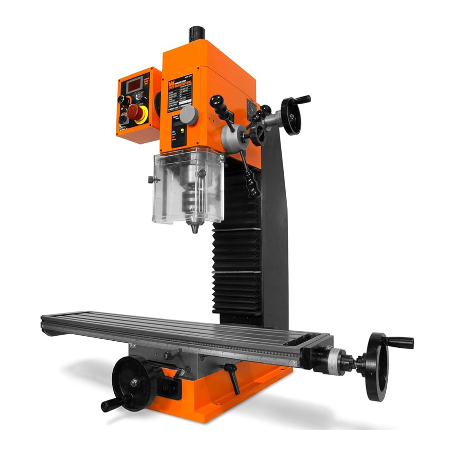
KNOW YOUR MILLING MACHINE
TOOL PURPOSE
Remove material from your workpiece with your WEN Benchtop Mill. Refer to the following diagrams to become familiarized with all the parts and controls of your milling machine. The components will be referred to later in the manual for assembly and operation instructions.
MILLING MACHINE

AXES
 | Z-Axis | Up & Down |
| X-Axis | Left & Right | |
| Y-Axis | Front & Back |
TOOL PURPOSE
Remove material from your workpiece with your WEN Benchtop Mill. Refer to the following diagrams to become familiarized with all the parts and controls of your milling machine. The components will be referred to later in the manual for assembly and operation instructions.
CONTROL PANEL

ASSEMBLY & ADJUSTMENTS
To prevent injury from accidental operation, make sure the tool is switched OFF and unplugged from the power source before assembling the tool or making any adjustments.
CLEANING THE SURFACES
Your tool comes protected with a layer of heavy-duty anti-rust coating. Remove the protective coating from surfaces using a soft cloth, moistened with kerosene (do not use cellulose-based solvents such as paint thinner or lacquer thinner, as these will damage the painted surfaces). Apply a light layer of good-quality machine oil onto the machine's surfaces to protect from rust and corrosion.
MOUNTING TO A BENCHTOP
For safe operation, the machine must be securely mounted onto a flat, secure workbench. Place the workbench away from direct sunlight, high moisture, or dust.
Position the machine on the benchtop and leave enough space around the machine for table travel. For unrestricted handwheel operation, make sure the cross feed and longitudinal feed handwheels extend out beyond the edge of the benchtop. Square the machine to the benchtop using a precision level.
Drill four 10 mm-diameter mounting holes on the benchtop (same size as the machine's mounting hole). Mount the machine using four MIO hex bolts, eight flat washers, four lock washers, and four hex nuts (mounting hardware not included) (Fig. 2).

INSTALLING THE HANDWHEELS
The two handwheels have been initially installed in the reversed direction for shipping purposes. Unscrew the handwheels and install them in the correct orientation (Fig. 3 - 1)

PREPARING VISES TO SECURE WORKPIECE
A vise (not included) is a crucial attachment to hold your workpiece in place when using the milling machine. You can purchase a milling vise or quick vise that is suitable for your workpiece and milling operation. The WEN 33124A 3.5 inch Quick Release Vise is perfect for holding your workpieces.
You may also use clamping kits to hold the workpieces to the machine's worktable. Follow the instructions with your accessory for proper installation and operation.
Your machine can work as both a milling and drilling machine, depending on the type of cutter that is installed. Refer to the introduction below for some common cutter holders and cutting tools that you can install onto your machine.
CUTTER HOLDER
The two most common cutting tools for the milling machine are drill bits and end mills. Drill bits are held in place by drill chucks (one included), while end mills are held in place by either collets or end mill holders (not included). Use the suitable holder for your cutting bit. The shank taper is R8.
- Drill Chucks The included drill chuck is ONLY able to hold drill bits for drilling operations. It is NOT able to hold milling bits. For end milling or face milling operations, collets or end mill holders are needed.
- Collets (not included) Collets are shorter than end mill holders to allow more vertical work area. It secures the end mill all the way around the shank to provide a better grip. They are also less expensive than end mill holders. The WEN 33182A 8-Piece Imperial Steel Collet Set is a great set to hold you over.
- End Mill Holders (not included) End mill holders are longer than collets and so the cutter can reach closer to the machine's worktable. The end mill is secured in the holder by a set screw that bears on the flat shank of the end mill. Changing end mills is easier to do on an end mill holder. They are also more robust than collets and are less prone to wearing out.
Collets, end mill holders, and drill chucks are held in the spindle by the drawbar (Part No. .2-46). The drawbar is tightened from the top of the spindle and extends through the spindle to the holder/chuck. When tightening the drawbar, make sure it is snug in the spindle threads, but do not overtighten.
CUTTING TOOLS
An end mill is the most common type of cutting tool for the milling machine. While a drill bit can only make plunge cuts in the vertical direction, an end mill can cut from the side of the workpiece. Some can also make plunge cuts.
- End Mills End mills can be classified into center-cutting and non-center-cutting mills. In a center-cutting mill, the flutes meet in the center on the tip of the end mill. This allows the mill to be plunged into the workpiece as is done with a drill press. In a non-center-cutting mill, the flutes do not meet at the tip, leaving a gap with no flutes in the center. The non-center-cutting mill can only cut from the side of the workpiece. It is recommended to use centercutting mills for their cutting versatility.
End mills can also be classified into 2-flute and 4-flute end mills, identified by the number of flutes on the tip of the mill. Commonly, 2-flute end mills are used for making bigger cuts or when cutting soft metals such as aluminum, as there is more room between the flutes to extract larger chips. 4-flute end mills can produce a better finish because there are twice as many cutting edges, each taking off less material. These end mills are used more commonly on harder metal such as steel and brass. - Drill bits Drill bits can be used on the milling machine for it to function as a drill press. However, drill bits are not designed to cut from the sides as they are not built to withstand the lateral forces imposed by sideways cutting. DO NOT USE DRILL BIT IN PLACE OF AN END MILL.
REMOVING DRILL CHUCK
The drill chuck and taper shank are pre-installed on your milling machine. To replace the drill chuck with a collet or end mill holder, follow the steps below for removing the drill chuck. Cover the table with a spare towel or rag to protect it from getting damaged, in case parts or bits are dropped onto the table.
- Make sure the machine is unplugged to prevent accidental starting.
- Remove 3 cap hex screws securing drawbar cap (Fig. 4 - 1) to the headstock.

- Secure the spindle (Fig. 5 - 1) from the bottom with the spindle wrench and loosen the drawbar from the top by using the 8 mm hex wrench and turning the drawbar only one full turn counter clockwise.

![warning]() NOTE: Do not completely unscrew the drawbar from the spindle. Doing so before the next step of striking it with a hammer can potentially damage the threads on both the drawbar and the arbor.
NOTE: Do not completely unscrew the drawbar from the spindle. Doing so before the next step of striking it with a hammer can potentially damage the threads on both the drawbar and the arbor. - Tap the top of the drawbar with a dead-blow or brass-head hammer to release the taper of the drill chuck.
- Hold onto the drill chuck while fully unthreading the drawbar. Once the drawbar is unthreaded, carefully remove the drill chuck from the spindle.


INSTALLING DRILL CHUCK / COLLET / END MILL HOLDER
- Make sure the machine is unplugged to prevent accidental starting.
- Align the keyway of the chuck/collet with the pin inside the spindle taper. Firmly press the chuck/collet into the spindle taper to seat it.
- Hold the chuck/collet in the spindle and insert the drawbar into the spindle from the top. Thread the spindle into the chuck/collet and hand-tighten tighten the drawbar.
- Use the 8 mm hex wrench in the drawbar and the spindle wrench in the spindle to tighten the drawbar securely.
ADJUSTING TABLE TRAVEL
The milling machine's worktable can be adjusted along the X axis and Y axis to accurately control the cutting location. The gauge on each handwheel indicates the distance of travel.
- To move the table along the longitudinal (X) axis (left and right), loosen the longitudinal feed lock lever (Fig. 6 - 1), engage the cross axis handwheel (Fig. 6 - 2) with the clutch teeth and rotate the longitudinal handwheel. Tighten the longitudinal feed lock lever to lock the longitudinal travel.

- To move the table forward and back along the cross (Y) axis, loosen the cross feed lock lever, and rotate the cross feed handwheel (Fig. 6 - 3). Tighten the cross feed lock lever to lock the cross travel.

NOTE: The lock lever can be pulled outwards and repositioned on the screw if the handle cannot be completely rotated due to interference with another part.
ADJUSTING THE SPINDLE DEPTH
For normal feeding, the downfeed selector knob (Fig. 7 - 1) should be lose and disengaged. Rotate the downfeed feed handles (Fig. 7 - 2) to bring the headstock up or down. Use the digital depth readout in the front of the machine to read the cutting depth.

For fine feeding adjustment (down to 0.001 inch increment), rotate the downfeed selector knob clockwise (Fig. 8 - 1) until it is tight. Then rotate the fine downfeed knob (Fig. 8 - 2) to make fine adjustments to the headstock position. Use the digital depth readout in the front of the machine to read the cutting depth.

NOTE: The spindle is equipped with a depth lock. To engage the depth lock, insert the 8 mm hex wrench in the depth lock and rotate clockwise until it is tight and engaged. To disengage the spindle depth lock, insert the 8 mm hex wrench and rotate the spindle depth lock counter-clockwise until it is loose and the spindle can move smoothly with the normal or fine downfeed handles. Be aware not to try to adjust the spindle depth while the spindle depth lock is engaged as doing so might cause extreme damage to the spindle.
ADJUSTING HEADSTOCK HEIGHT
The headstock on your mill can be adjusted up and down to accommodate short or tall workpieces and enables you to change tools mid project. The dovetail design creates precise Z-axis movement that allows you to keep your workpiece aligned when changing the headstock height or changing tooling.
- Ensure the machine is unplugged to prevent accidental starting.
- Loosen the Z-axis lock handle (Fig. 9 - 1).

- Turn the Z-axis handwheel (Fig. 10 - 1) to adjust the height of the headstock. Turn the handwheel clockwise to raise the headstock and counter-clockwise to lower it. Each full rotation of the handwheel moves the headstock 0.05".

- Lock the Z-axis lock handle once the headstock is adjusted to the desired height.


DETERMINING THE SPEED SETTINGS
The suitable operating speed depends on the size and material of the workpiece. Generally, use higher speeds for cutting softer materials and smaller holes; use lower speeds for cutting harder materials and bigger holes.
Your machine has a range of 100 - 2000 RPM. Use the spindle speed knob (Fig. 11 - 1) on the control panel to select the desired speed range.

Your machine is also equipped to run in the forwards and reverse directions. Flip the direction selector knob (Fig. 11 - 2) to either forwards or reverse to chose the desired direction.
Do not change the direction selector knob when the machine is running! Always turn the speed range knob to 0 before flipping the direction selector knob to either off or the other direction.
TURNING ON / OFF AND ADJUSTING THE SPEED
The speed adjustment knob on the front of the control panel (Fig. 12 - 1) turns the machine ON and OFF and adjusts the speed within the unit's capable speed range.

- Always make sure the speed adjustment knob is in the OFF setting before plugging in the machine
- Release the E-Stop switch (Fig. 12 - 2) by rotating the switch clockwise, allowing the button to spring outward.
- Select a direction for the spindle to turn (Fig. 12 - 3).
- Turn ON the machine by rotating the knob clockwise. A "click" will be heard as the motor is turned ON, but the spindle will not rotate until the knob is turned further clockwise.
- SLOWLY rotate the knob further and allow the speed to increase.
![]()
It is crucial to adjust the speed slowly or you may risk damaging the gears. - Give the machine an ample amount of time to ramp up to the operating speed before lowering the cutting tool into the workpiece. The current speed will show on the LED speed display (Fig. 1 2 - 4).
- To turn OFF the machine, SLOWLY rotate the speed adjustment knob counterclockwise until a "click" is heard and the knob points to the 0 position, then turn the direction selector knob to the OFF position. For emergency stop, press down the E-Stop button (Fig. 12 - 2). Make sure to always return the speed adjustment knob and the direction selector knob to the OFF position so that you don't risk accidentally starting the machine when the Emergency stop button is released.
OPERATION
To prevent serious injury, make sure all the warnings and instructions have been read and understood before operating this tool.
Always wear ANSI Z87.1 -approved eye protection and a face shield/dust mask when using this machine. Chips and dust fly at high speed during operation, and may cause injuries if they hit you.
PRIOR TO OPERATION
Check that the following requirements are met before plugging in the machine:
- The anti-rust protection has been cleared off from the machine.
- All obstacles have been cleaned and removed from the machine area and worktable.
- All adjustment tools (chuck key, rod, wrenches) have been removed from the machine.
- The cutter is properly installed and tightened in the holder.
- The workpiece is properly secured in a milling vise or quick vise (not included).
- The workpiece position has been adjusted on the X and Y axes to suit your task.
- The protective shield is in position.
- You are wearing ANSI Z87.1-approved eye protection and a face shield/dust mask.
DRILLING / MILLING OPERATIONS
- Install the suitable holder/chuck and cutter bit. Tighten them securely.
- Slowly rotate the speed adjustment knob (Fig. 12 - 1) to turn ON and set it to the appropriate speed. Wait a few seconds for the machine to reach full speed.
![]()
Do not turn on the machine while the cutter is contacting the workpiece. -
- DRILLING OPERATION. Pull the feed handle towards you to lower the cutter into the workpiece. Use the digital depth read out on the front of the unit to determine the depth of the cut.
- MILLING OPERATION. Pull the feed handle towards you to lower the cutter to the desired depth and tighten the spindle depth lock. Rotate handwheels to make a cut along the X or Y axis.
![warning]() NOTE: Make your cut in several progressive passes, instead of trying to take off too much material in one pass.
NOTE: Make your cut in several progressive passes, instead of trying to take off too much material in one pass.
- When the cut is complete, clear the cutter from the workpiece.
- Rotate the speed adjustment knob to the OFF position. Wait for the cutter to come to a complete stop and raise the headstock all the way to the upper position.
OVERLOAD PROTECTION
The overload protection will shut off the machine automatically during an overload. When this happens, the yellow overload light on the right control box will illuminate.
The machine may overload if the feed rate is too fast or if the cutting depth is too deep. When this happens, rotate the speed adjustment knob to the OFF position. Wait a few minutes to allow the motor to cool down and start the machine again. This time, reduce the feeding rate and cutting depth to prevent overloading the motor again.
MAINTENANCE
To avoid accidents, make sure the power switch is in the OFF position and unplug the tool from the electrical outlet before cleaning or performing any maintenance. Servicing of the tool must be performed by a qualified technician.
GENERAL MAINTENANCE
- Before each use, inspect the general condition of the tool. Check for:
- Loose hardware,
- Misalignment or binding of moving parts,
- Damaged cord/electrical wiring,
- Cracked or broken parts, and
- Any other condition that may affect its safe operation.
- After every use, wipe the tool with a soft cloth. Do not let water enter the tool. Clean the worktable and apply a small amount of general purpose machine oil to protect the worktable.
- Keep the top ventilation openings free from dust and debris to prevent the motor from overheating.
- Store the tool in a clean and dry place away from the reach of children.
CUTTER & TAPER SHANK MAINTENANCE
Use a rag to protect your hands while handling or installing the cutter to prevent injuries. Keep the taper shank and cutter shank clean. Always use sharp cutters; do not use if the cutter is dull or damaged. Store the cutter and holder in a wooden or plastic box after use to maintain its condition.
LUBRICATION
To ensure smooth operation of the machine, keep the moving contact surfaces lubricated. Fill included oil bottle with lubricating oil ISO 68 or SAE 20W non-detergent oil, and inject the oil onto the contact surfaces before operation.
- Base and saddle slide face
- Saddle and worktable slide face
- Column and bevel center slide face
- Column and headstock slide face.
Then, apply light-weight lithium based lubricating grease onto the following parts.
- X-Axis feeding leadscrew (saddle)
- Y-axis feeding leadscrew (worktable)
- Z-axis feeding gear rack (column)
To avoid accidents, make sure the power switch is in the OFF position and unplug the tool from the electrical outlet before cleaning or performing any maintenance. Servicing of the tool must be performed by a qualified technician.
GIBS ADJUSTMENT
The gib act as a sliding interface between two slide faces. The gibs have been pre-adjusted from the manufacturer and should not require further adjustment until about after a year of operation. In order to maintain mechanical precision, the gib needs to be adjusted to maintain the correct pressure between the two slide faces. Check and adjust the gibs every year, more frequently if under heavier usage.
There are 4 gibs on this machine. Refer to the exploded view and parts list to locate the gibs below:
- X-axis gib (Part No. 33075-409), between the base and the saddle seat slide surface.
- Y-axis gib(Part No. 33075-424), between the sadle seat and worktable slide face.
- Z-axis gib (Part No. 33075-216), between column and headstock slide face.
- Ensure the associated travel lock knobs are loose.
- Locate the respective gib screws, there will be one on each end of the gib. Loosen one screw and tighten the other the same amount with a flat head screw driver.
- Test the work table or head stock travel to ensure smooth but not too tight movement.
TROUBLESHOOTING GUIDE
Stop using the generator immediately if any of the following problems occur or risk serious personal injury. If you have any questions, please contact customer service at 1-800-232-1195 (M-F 8-5 CST), or email techsupport@wenproducts.com.
| Machine does not power on or the breaker immediately trips. |
|
|
| Mill is underpowered or stalls |
|
|
| Machine is excessively noisy or vibrating. |
|
|
| FWD/REV switch does not turn work |
|
|
| Table is difficult to move |
|
|
| Spindle speed readout does not display proper speeds or any readout. |
|
|
| Digital depth readout does not display proper measurement or does not turn on. |
|
|
To purchase accessories for your tool, visit WENPRODUCTS.COM
8-Piece 2-Flute HSS End Mill Set for Milling Machines Model 33108A
8-Piece Imperial Steel Collet Set for R8 Metal Milling Machines Model 33182A
3.5-Inch Quick-Release Vise for Milling Machines, Drill Presses, and Workbenches Model 33124A
For replacement parts visit WENPRODUCTS.COM
Have product questions? Need technical support?
Please feel free to contact us:
1-800-232-1195 (M-F 8AM-5PM CST)
TECHSUPPORT@WENPRODUCTS.COM

Documents / Resources
References
Download manual
Here you can download full pdf version of manual, it may contain additional safety instructions, warranty information, FCC rules, etc.
Download WEN 33075, 33075T - 11-Amp Variable Speed 16-Inch Benchtop Milling Machine Manual
Advertisement


Need help?
Do you have a question about the 33075 and is the answer not in the manual?
Questions and answers