Wen 4210 Manual
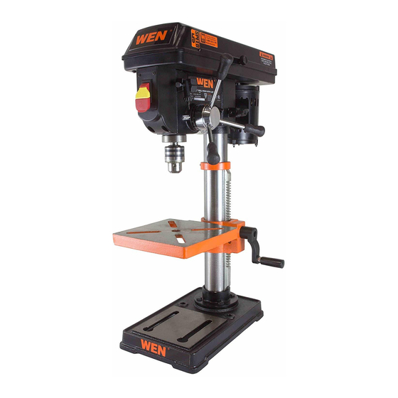
10" drill press with laser crosshair
Hide thumbs
Also See for 4210:
- Operator's manual (28 pages) ,
- Owner's manual (22 pages) ,
- Manual (24 pages)
Advertisement
Table of Contents
- 1 Table of Contents
- 2 Specifications
- 3 Introduction
- 4 General Safety Rules
- 5 Specific Safety Rules for the Drill Press
- 6 Electrical Information
- 7 Know Your Drill Press
- 8 Assembly & Adjustments
- 9 Operation
- 10 Maintenance
- 11 Troubleshooting Guide
- 12 Exploded View & Parts List
- 13 Warranty Statement
- Download this manual
For replacement parts visit
WENPRODUCTS.COM
Your new tool has been engineered and manufactured to WEN's highest standards for dependability,
ease of operation, and operator safety. When properly cared for, this product will supply you years of
rugged, trouble-free performance. Pay close attention to the rules for safe operation, warnings, and
cautions. If you use your tool properly and for its intended purpose, you will enjoy years of safe, reli-
able service.
NOTICE: Please refer to wenproducts.com for the most up-to-date instruction manual.
10" DRILL PRESS WITH
LASER CROSSHAIR
IMPORTANT:
NEED HELP? CONTACT US!
Have product questions? Need technical support?
Please feel free to contact us at:
800-232-1195
techsupport@wenproducts.com
WENPRODUCTS.COM
MODEL 4210, 4210T
(M-F 8am-5pm CST)
ZJ4113Z
4005911
Advertisement
Table of Contents

Subscribe to Our Youtube Channel
Related Manuals for Wen 4210


Summary of Contents for Wen 4210
- Page 1 4005911 IMPORTANT: Your new tool has been engineered and manufactured to WEN’s highest standards for dependability, ease of operation, and operator safety. When properly cared for, this product will supply you years of rugged, trouble-free performance. Pay close attention to the rules for safe operation, warnings, and cautions.
-
Page 2: Table Of Contents
Operation ....................19 Maintenance .................... 21 Troubleshooting Guide ................22 Exploded View & Parts List ..............24 Warranty Statement ................27 SPECIFICATIONS Model Numbers 4210, 4210T Motor 120 V, 60 Hz, 3.2A Chuck Capacity 1/2" Spindle Stroke 2-1/2" Spindle Taper... -
Page 3: Introduction
INTRODUCTION Thanks for purchasing the WEN Drill Press. We know you are excited to put your tool to work, but first, please take a moment to read through the manual. Safe operation of this tool requires that you read and understand this operator’s manual and all the labels affixed to the tool. -
Page 4: General Safety Rules
GENERAL SAFETY RULES Safety is a combination of common sense, staying alert and knowing how your item works. SAVE THESE SAFETY INSTRUCTIONS. WARNING: Read and understand all warnings, cautions and operating instructions before using this tool. Failure to follow all instructions listed below may result in personal injury and tool damage. WORK AREA SAFETY 1. - Page 5 GENERAL SAFETY RULES 4. Prevent unintentional starting. Ensure the switch is in the off-position before connecting to power source and/or battery pack, picking up or carrying the tool. Carrying power tools with your finger on the switch or energizing power tools that have the switch on invites accidents. 5.
-
Page 6: Specific Safety Rules For The Drill Press
SPECIFIC RULES FOR THE DRILL PRESS WARNING: Do not let comfort or familiarity with the product replace strict adherence to product safety rules. Failure to follow the safety instructions may result in serious personal injury. 1. TOOL PURPOSE. This drill press is designed to drill through metal and wood. Drilling through other materials could result in fire, injury, or damage to the workpiece. - Page 7 SPECIFIC RULES FOR THE DRILL PRESS 12. DRILLING THE WORKPIECE. • Allow spindle to reach full speed before drilling the workpiece. • Never start the machine with the drill bit pressed against the workpiece. • Adjust the table or depth stop to avoid drilling into the table. •...
-
Page 8: Electrical Information
ELECTRICAL INFORMATION GROUNDING INSTRUCTIONS IN THE EVENT OF A MALFUNCTION OR BREAKDOWN, grounding provides the path of least resistance for an electric current and reduces the risk of electric shock. This tool is equipped with an electric cord that has an equipment grounding conductor and a grounding plug. The plug MUST be plugged into a matching outlet that is properly installed and grounded in accordance with ALL local codes and ordinances. -
Page 9: Know Your Drill Press
KNOW YOUR DRILL PRESS TOOL PURPOSE Drill presses are mainly used to drill clean, precise cylindrical holes into workpieces or enlarge existing holes. You may also find other uses for your drill press such as reaming, countersinking, counterboring, tapping, etc. Refer to the diagram below and on Page. 10 to become familiarized with the parts and con- trols of your Drill Press. -
Page 10: Assembly & Adjustments
ASSEMBLY & ADJUSTMENTS UNPACKING With the help of a friend or trustworthy foe, carefully remove the drill press from the packaging. Make sure to take out all contents and accessories. Do not discard the packaging until the drill press is completely assembled. - Page 11 ASSEMBLY & ADJUSTMENTS WARNING: Do not plug in or turn on the tool until it is fully assembled according on the instruc- tions. Failure to follow the safety instructions may result in serious personal injury. ATTACHING COLUMN ASSEMBLY TO BASE See Fig.
- Page 12 ASSEMBLY & ADJUSTMENTS DRILL PRESS HEAD TO COLUMN See Fig. 6 CAUTION: The drill press head is heavy. To avoid injury, two people should lift it into position. 1. Carefully lift the drill press head assembly and position it over the column (Fig.
- Page 13 ASSEMBLY & ADJUSTMENTS 3. Completely remove any burrs found on the inner mating surface of the chuck with a diamond coated tool or a fine file. Use a grade 000 steel wool pad to lightly go over the chuck and spindle.
- Page 14 ASSEMBLY & ADJUSTMENTS INSTALL LASER BATTERIES (PRE-INSTALLED) 1. Turn off the drill laser. 2. Pull the tab located below the laser switch and lift up the laser switch cover (Fig. 10). 3. Install two AAA batteries into the battery slots and close the switch cover (Fig.
- Page 15 ASSEMBLY & ADJUSTMENTS TILT THE TABLE 1. Loosen the bevel lock bolt (Fig. 14 - 1) with a 19 mm socket or wrench (not included). 2. Tilt the table to the desired angle, using the bevel scale (Fig. 15) as a basic guide. 3.
- Page 16 2. Turn the depth scale ring (Fig. 17 - 2) to the desired depth. 3. Lock the scale ring in place by tightening the depth lock- ing knob. SPEED ADJUSTMENT For a video demonstration using the WEN 8-Inch Drill Press, visit http://bit.ly/1LGcLIb Fig. 17 1. Unplug the drill press.
- Page 17 ASSEMBLY & ADJUSTMENTS 1. Unplug the drill press. 2. Place a workpiece on the table. 3. Turn the laser switch to the ON position. 4. Lower the drill bit to meet the workpiece. The two laser lines Fig. 19 should cross where the drill meets the workpiece. 5.
- Page 18 ASSEMBLY & ADJUSTMENTS REPLACE THE BELT WARNING: Disconnect the drill press from the power source before replacing the belt. 1. Open the housing cover. Loosen the belt tension locking knob (Fig. 21). Fig. 21 2. Remove the belt from the housing cover if it is bro- ken.
-
Page 19: Operation
OPERATION ON/OFF SWITCH WITH SAFETY KEY 1. To turn the drill press ON, insert the yellow safety key (Fig. 22 - 1) into the switch housing (Fig. 22 - 2). As a safety feature, the switch cannot be turned ON without the safety key. 2. - Page 20 OPERATION GENERAL DRILLING GUIDELINES - DRILLING A HOLE WARNING: To prevent the workpiece and the backup material from slipping from your hand while drilling, position the workpiece and backup material to the left side of the column. If the workpiece and the backup material are not long enough to reach the column, clamp the workpiece and backup mate- rial to the table.
-
Page 21: Maintenance
WARNING: Any attempt to repair or replace electrical parts on this tool may be hazardous. Servic- ing of the tool must be performed by a qualified technician. When servicing, use only identical WEN replacement parts. Use of other parts may be hazardous or induce product failure. ROUTINE INSPECTION Before each use, inspect the general condition of the tool. -
Page 22: Troubleshooting Guide
WARNING: Stop using the tool immediately if any of the following problems occur. Repairs and replacements should only be performed by an authorized technician. For any questions, please contact our customer service at (800) 232-1195, M-F 8-5 CST or email us at techsupport@wen- products.com. - Page 23 WARNING: Stop using the tool immediately if any of the following problems occur. Repairs and replacements should only be performed by an authorized technician. For any questions, please contact our customer service at (800) 232-1195, M-F 8-5 CST or email us at techsupport@wen- products.com.
-
Page 24: Exploded View & Parts List
EXPLODED VIEW & PARTS LIST ... - Page 25 EXPLODED VIEW & PARTS LIST Part No. Description Qty. Part No. Description Qty. 4210B-037 Switch Plate 4210B-001 V-belt 4210B-038 Thread Forming Screw 4210B-002 Motor Pulley 4210B-039 Switch 4210B-003 Set Screw 4210B-040 Pan Head Screw 4210B-004 Power Cord 4210B-041 Lock Washer 4210B-005 Spindle Pulley 4210B-042...
- Page 26 EXPLODED VIEW & PARTS LIST Part No. Description Qty. Part No. Description Qty. 4210B-073 Flat Washer 4210B-091 Table Support 4210B-074 Hex Head Bolt 4210B-092 Table 4210B-075 Motor 4210B-093 Washer 4210B-076 Lock Washer 4210B-094 Hex Head Bolt 4210B-077 Chuck Key Seat 4210B-095 Column Collar 4210B-078...
-
Page 27: Warranty Statement
(2) years from date of purchase. Ninety days for all WEN products if the tool is used for professional or commercial use. SELLER’S SOLE OBLIGATION AND YOUR EXCLUSIVE REMEDY under this Limited Warranty and, to the ex-... - Page 28 THANKS FOR REMEMBERING...
Need help?
Do you have a question about the 4210 and is the answer not in the manual?
Questions and answers
laser does not work after new batteries installed