Table of Contents
Advertisement
Quick Links
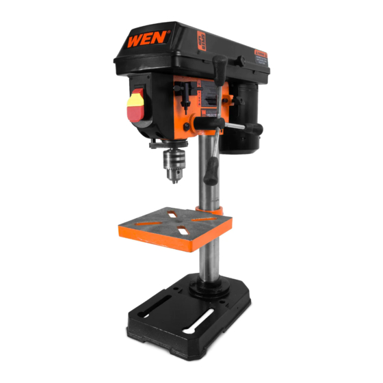
MODEL 4208, 4208T
8-INCH 5-SPEED
DRILL PRESS
Instruction Manual
NEED HELP? CONTACT US!
Have product questions? Need technical support? Please feel free to contact us:
1-800-232-1195 (M-F 8AM-5PM CST)
TECHSUPPORT@WENPRODUCTS.COM
IMPORTANT: Your new tool has been engineered and manufactured to WEN's highest standards for dependability,
ease of operation, and operator safety. When properly cared for, this product will supply you years of rugged,
trouble-free performance. Pay close attention to the rules for safe operation, warnings, and cautions. If you use
your tool properly and for its intended purpose, you will enjoy years of safe, reliable service.
WENPRODUCTS.COM
For replacement parts and the most up-to-date instruction manuals, visit
Advertisement
Table of Contents

Subscribe to Our Youtube Channel
Related Manuals for Wen 4208T


Summary of Contents for Wen 4208T
- Page 1 1-800-232-1195 (M-F 8AM-5PM CST) TECHSUPPORT@WENPRODUCTS.COM IMPORTANT: Your new tool has been engineered and manufactured to WEN’s highest standards for dependability, ease of operation, and operator safety. When properly cared for, this product will supply you years of rugged, trouble-free performance. Pay close attention to the rules for safe operation, warnings, and cautions. If you use your tool properly and for its intended purpose, you will enjoy years of safe, reliable service.
-
Page 2: Table Of Contents
CONTENTS WELCOME Introduction ..................... 3 Specifications ....................3 SAFETY General Safety Rules ..................4 Drill Press Safety Warnings ................6 Electrical Information ..................8 BEFORE OPERATING Unpacking & Packing List ................9 Know Your Drill Press ..................10 Assembly & Adjustment ................. 11 OPERATION &... -
Page 3: Welcome
INTRODUCTION Thanks for purchasing the WEN Drill Press. We know you are excited to put your tool to work, but first, please take a moment to read through the manual. Safe operation of this tool requires that you read and understand this operator’s manual and all the labels affixed to the tool. -
Page 4: Safety
GENERAL SAFETY RULES WARNING! Read all safety warnings and all instructions. Failure to follow the warnings and instructions may result in electric shock, fire and/or serious injury. Safety is a combination of common sense, staying alert and knowing how your item works. The term “power tool” in the warnings refers to your mains-operated (corded) power tool or battery-operated (cordless) power tool. - Page 5 GENERAL SAFETY RULES WARNING! Read all safety warnings and all instructions. Failure to follow the warnings and instructions may result in electric shock, fire and/or serious injury. Safety is a combination of common sense, staying alert and knowing how your item works. The term “power tool” in the warnings refers to your mains-operated (corded) power tool or battery-operated (cordless) power tool.
-
Page 6: Drill Press Safety Warnings
DRILL PRESS SAFETY WARNINGS WARNING! Do not operate the power tool until you have read and understood the following instructions and the warning labels. 1. TOOL PURPOSE. This drill press is designed to 8. WORKPIECE REQUIREMENTS. drill through metal and wood. Drilling through other •... - Page 7 DRILL PRESS SAFETY WARNINGS WARNING! Do not operate the power tool until you have read and understood the following instructions and the warning labels. 15. After turning off the drill press, wait until the CALIFORNIA PROPOSITION 65 WARNING spindle comes to a complete stop before touching Some dust created by power sanding, sawing, grind- the workpiece.
-
Page 8: Electrical Information
ELECTRICAL INFORMATION GROUNDING INSTRUCTIONS In the event of a malfunction or breakdown, grounding provides the path of least resistance for an electric current and reduces the risk of electric shock. This tool is equipped with an electric cord that has an equipment grounding conductor and a grounding plug. -
Page 9: Before Operating
UNPACKING & PACKING LIST WARNING! Do not plug in or turn on the tool until it is fully assembled according to the instructions. Failure to follow the safety instructions may result in serious personal injury. UNPACKING With the help of a friend or trustworthy foe, carefully remove the Drill Press from the packaging. Make sure to take out all contents and accessories. -
Page 10: Know Your Drill Press
KNOW YOUR DRILL PRESS TOOL PURPOSE Drill clean, precise cylindrical holes into workpieces or enlarge existing holes with your Drill Press. Refer to the fol- lowing diagrams to become familiarized with all the parts and controls of your Drill Press. The components will be referred to later in the manual for assembly and operation instructions. -
Page 11: Assembly & Adjustment
ASSEMBLY & ADJUSTMENTS Fig. 2 WARNING! Do not plug in or turn on the tool until it is fully assembled according to the instructions. Failure to follow the safety instructions may result in serious personal injury. ATTACHING COLUMN ASSEMBLY TO BASE 1. - Page 12 ASSEMBLY & ADJUSTMENTS MOUNTING THE DRILL PRESS Fig. 5 The drill press must be securely fastened through the mounting holes (Fig. 5 - 1) to a stand or workbench with heavy-duty fasteners (Fig. 5 - 2) (fasteners and mounting hardware not included). This will prevent the drill press from tipping over, sliding, or walking during operation.
- Page 13 ASSEMBLY & ADJUSTMENTS REMOVING THE CHUCK Fig. 7 NOTE: To avoid possible damage to the drill or chuck, be prepared to catch the chuck as it falls. Placing a towel on the drill press table can soften the impact if you do drop the chuck.
- Page 14 ASSEMBLY & ADJUSTMENTS INSTALLING A DRILL BIT Fig. 10 1. Place the chuck key (Fig. 10 - 1) into the side keyhole of the chuck (Fig. 10 - 2), meshing the key with the gear teeth. 2. Turn chuck key counterclockwise to open the chuck jaws. 3.
- Page 15 ASSEMBLY & ADJUSTMENTS SPINDLE RETURN SPRING Fig. 13 The spindle is equipped with an auto-return mechanism. The main components are a spring and a notched housing. The spring was properly adjusted at the factory and should not be readjusted unless absolutely necessay. WARNING! Alwasy wear work gloves to prevent injury during spingle return spring adjustments.
-
Page 16: Operation & Maintenance
OPERATION ON / OFF SWITCH Fig. 16 1. To turn drill press ON, insert the yellow safety key (Fig. 16 - 1) into the switch housing (Fig. 16 - 2). As a safety feature, the switch cannot be turned ON without the safety key. 2. -
Page 17: Maintenance
WARNING! Any attempt to repair or replace electrical parts on this tool may be hazardous. Servicing of the tool must be performed by a qualified technician. When servicing, use only identical WEN replacement parts. Use of other parts may be hazardous or induce product failure. - Page 18 MAINTENANCE CLEANING & STORAGE 1. After every operation, use a vacuum to remove sawdust or metal shavings from the tool surfaces, motor hous- ing and work area. Keep the ventilation openings free from dust and debris to prevent the motor from overheating. 2.
-
Page 19: Troubleshooting Guide
TROUBLESHOOTING GUIDE WARNING! Stop using the generator immediately if any of the following problems occur or risk serious personal injury. If you have any questions, please contact customer service at 1-800-232-1195 (M-F 8-5 CST), or email techsupport@wenproducts.com. PROBLEM CAUSE SOLUTION 1) Adjust the belt tension (see “Replacing the Belt”... - Page 20 TROUBLESHOOTING GUIDE WARNING! Stop using the generator immediately if any of the following problems occur or risk serious personal injury. If you have any questions, please contact customer service at 1-800-232-1195 (M-F 8-5 CST), or email techsupport@wenproducts.com. PROBLEM CAUSE SOLUTION 1) The workpiece is pinching the bit 1) Support or clamp the workpiece Drill bit binds in...
-
Page 21: Exploded View & Parts List
EXPLODED VIEW & PARTS LIST... - Page 22 EXPLODED VIEW & PARTS LIST Part No. Description Qty. Part No. Description Qty. 4208C-001 V Belt 4208C-040 Quill Collar 4208C-002 Motor Pulley 4208C-041 Hex Nut 4208C-003 Set Screw 4208C-042 Screw 4208C-004 Power Cord 4208C-043 Chuck with Key 4208C-005 Set Screw 4208C-044 Spindle 4208C-006...
-
Page 23: Warranty Statement
WARRANTY STATEMENT WEN Products is committed to building tools that are dependable for years. Our warranties are consistent with this commitment and our dedication to quality. LIMITED WARRANTY OF WEN PRODUCTS FOR HOME USE GREAT LAKES TECHNOLOGIES, LLC (“Seller”) warrants to the original purchaser only, that all WEN consumer power tools will be free from defects in material or workmanship during personal use for a period of two (2) years used for professional or commercial use. - Page 24 THANKS FOR REMEMBERING V. 2021.01.05...
Need help?
Do you have a question about the 4208T and is the answer not in the manual?
Questions and answers