
Related Manuals for Classic Exhibits SACAGAWEA DESIGNS VK-2108


Summary of Contents for Classic Exhibits SACAGAWEA DESIGNS VK-2108
- Page 1 Step 1 Order #xxxxx - Sacagawea - VK-2108 - General Layout 866.652.2100 10’ Plan View 20’ WHEN DISASSEMBLING ALUMINUM EXTRUSION, TIGHTEN ALL SETSCREWS AND LOCKS TO PREVENT LOSS DURING SHIPPING © 2009 w w w . c l a s s i c e x h i b i t s . c o m Page 1 of 3...
- Page 2 Step 2 Order #xxxxx - Sacagawea - General Information 866.652.2100 Using You Set-up Instructions: The Visionary Designs Set-up Instructions for Sacagawea displays are created Hex Key Tool Typical Connection Typical Connection specifically for your configuration. They are laid out sequentially, including an exploded view of the entire display and a logical series of detailed steps for assembly.
-
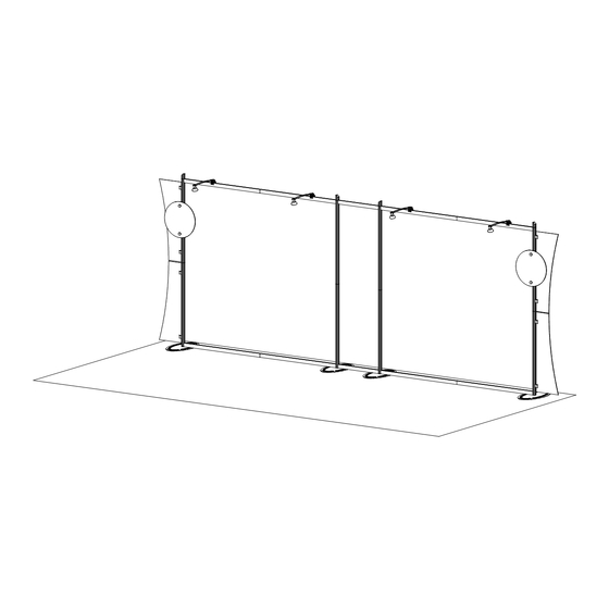
Page 3: Back View
Step 1 Order #xxxxx - Sacagawea - Backwall Assembly 866.652.2100 Steps: 1) Attach base plates [1] to lower verticals [2a,3a,2c,3c] with bolts. 2.5”h Angle-Cut 2) Connect upper verticals [2b,3b,2d,3d] to lower verticals [2a,3a,2c,3c] with connection bars [b]. Vertical Attachment 3) Connect horizontals [4a,4b] and [5a,5b] with connection bars [a]. 4) Connect vertical assemblies [2a/2b,3a/3b,2c/2d,3c/3d] with horizontal assemblies [4a/4b,5a/5b] Tighten setscrew and horizontals [4c,5c] as shown. - Page 4 Step 2 Order #xxxxx - Sacagawea - Counter and Wing Attachment 866.652.2100 Graphic Attachment Steps: Light Connection 1) Attach lights as indicated. Attach lights to 2) Attach wings to A10 clamps as shown. Graphic backwall where 3) Attach graphic signs to backwall as shown desired and tighten in place.
- Page 5 Order #xxxxx - Case Packing Instruction 866.652.2100 Top View of Each Level Halogen Lights Wing Panels Graphics Round Sign Setup Hardware (4) Base Plates Level 3 Level 1 Level 2 WHEN DISASSEMBLING ALUMINUM EXTRUSION, TIGHTEN ALL SETSCREWS AND LOCKS TO PREVENT LOSS DURING SHIPPING ©...
Need help?
Do you have a question about the SACAGAWEA DESIGNS VK-2108 and is the answer not in the manual?
Questions and answers