
Related Manuals for Classic Exhibits MAGELLAN DESIGNS VK-1088


Summary of Contents for Classic Exhibits MAGELLAN DESIGNS VK-1088
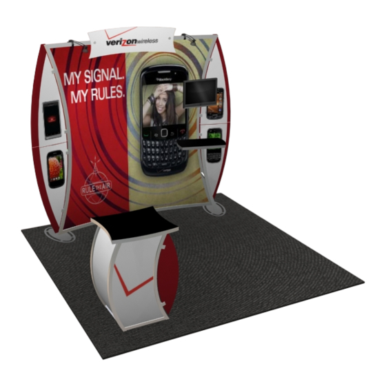
- Page 1 Step 1 Order #XXXXX - VK-1088 Magellan - General Layout 866.652.2100 10‘ Plan View 10‘ WHEN DISASSEMBLING ALUMINUM EXTRUSION, TIGHTEN ALL SETSCREWS AND LOCKS TO PREVENT LOSS DURING SHIPPING © 2012 w w w . c l a s s i c e x h i b i t s . c o m Page 1 of 3...
- Page 2 Step 2 Order #XXXXX - General Information 866.652.2100 Typical Connection Typical Connection Using You Set-up Instructions: The Visionary Designs Set-up Instructions for Magellan displays are created specifically for your configuration. They are laid out sequentially, including an exploded view of the entire display and a logical series of detailed steps for assembly.
- Page 3 Step 1 Order #XXXXX - Backwall Assembly 866.652.2100 Steps 1) Attach lower vertical extrusions [2a,3a] to base plates [1a,1b] as shown. 2) Attach upper vertical extrusions [2b,3b] to lower vertical extrusions [2a,3a] using connectors [a]. Part Description 3) Connect horizontal extrusions [4a,4b & 5a,5b] using connectors [b]. 1a/1b Base Plate 4) Attach horizontal assemblies [4a/4b,5a/5b] between vertical assemblies as shown.
- Page 4 Step 2 Order #XXXXX - Attachments 866.652.2100 Part Description Steps 1) Attach graphic header to backwall with screw caps. 6/6a/6b 1/1/1 Counter Support Extrusions 2) Attach back wings to back of frame with with stand-off barrles and screw caps. 3) Attach side wings to A10 clamps at the sides of frame. Stand-Off 4) Lock horizontal shelf supports [6a,6b] to backwall.
- Page 5 Step 3 Order #XXXXX - Pedestal Assembly 866.652.2100 Part Number Description 39.84” Curved Vertical Extrusion 39.84” Curved Vertical Extrusion w/ A10 Clamp 39.84” Curved Vertical Extrusion w/ A10 Clamp 39.84” Curved Vertical Extrusion 17”w Horizontal Extrusion 17”w Horizontal Extrusion 17”w Horizontal Extrusion w/ Door Stopper 17”w Horizontal Extrusion w/ Door Hinge Steps: 1) Connect front and back assemblies together using horizontals [11], placing infill between verticals and horizontals.
- Page 6 Order #XXXXX - Packing Instructions - Case 1 of 2 866.652.2100 Top View 6a/b Setup Hardware Wings Counter Level 1 Level 2 Level 3 WHEN DISASSEMBLING ALUMINUM EXTRUSION, TIGHTEN ALL SETSCREWS AND LOCKS TO PREVENT LOSS DURING SHIPPING © 2012 w w w .
- Page 7 Order #XXXXX - Packing Instructions - Case 2 of 2 866.652.2100 Top View Wing Panel and Infills 11 (4x) Internal Shelf Front Assembly Counter Top Back Assembly Level 1 Level 2 Level 3 Level 4 WHEN DISASSEMBLING ALUMINUM EXTRUSION, TIGHTEN ALL SETSCREWS AND LOCKS TO PREVENT LOSS DURING SHIPPING ©...
Need help?
Do you have a question about the MAGELLAN DESIGNS VK-1088 and is the answer not in the manual?
Questions and answers