Table of Contents
Advertisement
Quick Links
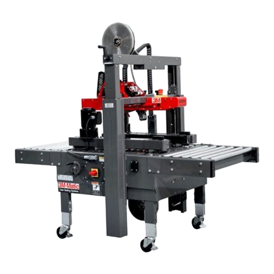
3M-MATIC
8000a-T
Modified Adjustable Case Sealer
Machine Serial Number:
The following attached pages are a current bill of materials of the parts for
your T-Table. This unit is designed for trouble-free operation. As with any
precision equipment however, regular maintenance is required.
Subject to change without notice
.
Advertisement
Chapters
Table of Contents
Troubleshooting

Related Manuals for 3M 3M-MATIC 8000a-T


Summary of Contents for 3M 3M-MATIC 8000a-T
- Page 1 3M-MATIC 8000a-T Modified Adjustable Case Sealer Machine Serial Number: The following attached pages are a current bill of materials of the parts for your T-Table. This unit is designed for trouble-free operation. As with any precision equipment however, regular maintenance is required.
- Page 2 This Machinery has been equipped with the following: 1. 6" x 36" T-Table Modification...
- Page 3 Serial No. For reference, record machine serial number here. "3M-Matic"and "AccuGlide" are Trademarks of, 3M Industrial Adhesives and Tapes 3M St. Paul, MN 55144-1000 3M Center, Building 220-5E-06 Printed in U.S.A.
- Page 4 This instruction manual covers safety aspects, handling and transport, storage, unpacking, preparation, installation, operation, adjustments, maintenance, troubleshooting, repair work and servicing plus parts list of the 3M-Matic 8000a-8000a3 adjustable case sealer. 3M Industrial Adhesives and Tapes 3M Center, Building 220-5E-06 St.
-
Page 5: Replacement Parts And Service Information
$10.00 restocking charge per invoice on returned parts 3M-Matic ™ , AccuGlide ™ and Scotch ™ 3M Industrial Adhesives and Tapes are Trademarks of 3M Center, Building 220-5E-06 3M St. Paul, MN 55144-1000 St. Paul, MN 55144-1000 Printed in U.S.A. - Page 6 THIS PAGE IS BLANK...
- Page 7 Order parts by part number, part description, and quantity required. Also, when ordering parts or additional manuals, include model/machine name, machine type, and serial number that are located on the identifi cation plate. 3M Industrial Adhesives and Tapes 3M-Matic , AccuGlide and Scotch ™...
- Page 8 THIS PAGE IS BLANK...
-
Page 9: Table Of Contents
TABLE OF CONTENTS - MANUAL 1: 8000a-8000a3 Adjustable Case Sealer (For Taping Head Information - See Manual 2 or 3: AccuGlide™ 3 Taping Heads - 2 Inch or 3 Inch) 8000a-8000a3 Adjustable Case Sealer Page Cover Page Replacement Parts and Service Information ................ i - ii Table of Contents ......................... - Page 10 THIS PAGE IS BLANK...
- Page 11 TABLE OF CONTENTS (continued) 5. Shipment, Handling, and Storage 5.1 Packed Machine Shipment and Handling ................16 5.2 Overseas Shipment Packaging (Optional) ................16 5.3 Handling and Transportation of Uncrated Machine ............. 16 5.4 Machine Storage ......................... 16 6. Unpacking 6.1 Uncrating ..........................
- Page 12 THIS PAGE IS BLANK...
- Page 13 TABLE OF CONTENTS (continued) 12. Operation 12.1 Operator’s Correct Working Position ................27 12.2 Starting the Machine ....................... 27 12.3 Starting Production ......................27 12.4 Tape Replacement ......................27 12.5 Box Size Adjustment ....................... 27 12.6 Cleaning ......................... 27 12.7 Table of Adjustments ......................
- Page 14 ABBREVIATIONS AND ACRONYMS LIST OF ABBREVIATIONS, ACRONYMS 3M-Matic - Trademark of 3M St. Paul, MN 55144- 1000 AccuGlide - Trademark of 3M St. Paul, MN 55144-1000 Scotch - Trademark of 3M St. Paul, MN 55144-1000 Drw. - drawing - for example Fig.
-
Page 15: Introduction
1-INTRODUCTION 1.1 Manufacturing Specifications / Description / Intended Use The 3M-Matic 8000a-8000a3 Adjustable Case Sealer with AccuGlide 3 Taping Heads is designed to apply a “C” clip of Scotch ® pressure-sensitive fi lm box sealing tape to the top and bottom center seam of regular slotted containers. -
Page 16: How To Read And Use The Manual
3M-Matic 8000a-8000a3 Adjustable case sealer All pages and diagrams are numbered. The spare 3M Industrial Adhesives and Tapes Division 3M Cen- parts lists are identifi ed by the fi gure identifi cation ter, Bldg. 220-5E-06 St. Paul, MN 55144-1000 (USA) number. -
Page 17: General Information
2-GENERAL INFORMATION 2.1 Data Identifying Manufacturer and Machine For Commercial Use Only 2.2 Data for Technical Assistance and Service 2014 June 8000a-8000a3 - NA... -
Page 18: Warranty / Contents
3M’s factory or an authorized service station designated by 3M. A part will be presumed to have become defective after its warranty period unless the part is received or 3M is notifi ed of the problem no later than fi... -
Page 19: Safety
3-SAFETY 3.1 General Safety Information 3.2 Explanation of Signal Word and Possible Consequences Read all the instructions carefully before starting work with the machine; please pay particular attention to This safety alert symbol identifi es important sections marked by the symbol: messages in this manual. -
Page 20: Table Of Warnings
3-SAFETY (continued) 3.3 Table of Warnings WARNING • To reduce the risk associated with mechanical and electrical hazards: − Read, understand, and follow all safety and operating instructions before operating or servicing the case sealer. Figure 3-2 − Allow only properly trained and qualifi... - Page 21 3-SAFETY (continued) WARNING To reduce the risk associated with • sharp blade hazards: − Keep hands and fi ngers away from WARNING tape cutoff blades under orange blade Sharp Blade guards. The blades are extremely sharp. Important! Tape cutting blade. Never remove the safety device which covers the blade on the top and bottom taping units.
-
Page 22: Operator's Qualifi Cations Defi Nition
3-SAFETY (continued) 3.4 Operator's Qualifications WARNING - Machine Operator - Mechanical Maintenance Technician - Electrical Maintenance Technician To reduce the risk associated with • - Manufacturer’s Technician/Specialist mechanical and electrical hazards: (See Section 3) − Read, understand, and follow all safety and operating instructions before operating or servicing the case sealer. -
Page 23: Operator's Required Skill Levels
3-SAFETY (continued) Skill 2a: Electrical Maintenance Technician 3.11 Operator's Skill Levels Required to Perform the Main Operations on the Machine This operator is trained to use the machine as the MACHINE OPERATOR and in addition is able to: • Work with the safety protection disconnected The Table shows the minimum operator's skill for •... -
Page 24: Component Locations
3-SAFETY (continued) 3.12 Component Locations Refer to Figure 3-9 below to acquaint yourself with the various components and controls of the case sealer. Also refer to Manual 2 for taping head components. Top Flap Compression Rollers Upper Taping Head Height Adjustment Emergency Handle Stop Button... -
Page 25: Table Of Warnings And Replacement Labels
78-8137-7403-7 78-8070-1336-8 (2) 78-8095-1141-9 STOP 78-8137-7402-9 78-8070-1366-5 78-8137-7404-5 78-8070-1318-6 78-8070-1329-3 78-8137-1331-6 78-8113-6717-2 78-8137-7406-0 78-8060-8481-6 78-8137-0886-0 Leg Height Adjustment Label (not shown) 78-8137-7404-5 3M Logo (not shown) 78-8113-6717-2 Figure 3-10 Replacement Labels / 3M Part Numbers 2014 June 8000a-8000a3 - NA... -
Page 26: Power Requirements
The machine is equipped with two 1/6 HP gearmotors and comes with an 2.4m [8 foot] standard neoprene covered power cord and a grounded plug. Contact your 3M Representative for power requirements not listed above. Contact your 3M Representative for power requirements not listed above. -
Page 27: Tape
4-SPECIFICATIONS (continued) 4.6 Tape Scotch ® pressure-sensitive fi lm box sealing tapes. 4.7 Tape Width 50mm [2 inch] minimum to 72mm [3 inch] maximum 4.8 Tape Roll Diameter Up to 406.4mm [16 inch] maximum on a 76.2mm [3 inch] diameter core. (Accommodates all system roll lengths of Scotch ®... - Page 28 Position - See Special Set-Up Procedure).Tape Leg Length - 2 3/4" [70mm] Special modif cations may be available for carton sizes not listed on previous page. Contact your 3M Representative for information. Note: The case sealer can accommodate most boxes within the size range listed above. However, if the box length (in direction of seal) to box height ratio is .6 or less, then several boxes should be test run to assure...
-
Page 29: Machine And Packaged Machine Dimensions
4-Specifications (continued) Right Side Optional Control Side Optional Exit Infeed Conveyor Conveyor Travel Optional Optional Exit Infeed Conveyor Conveyor Optional Casters 4.12 Machine Dimensions Minimum 1395 460* 105 ** [Inches] [38 1/2] [36 1/4] [55] [18] [24]* [4 3/16] [24.5] Maximum 2185 [Inches]... -
Page 30: Handling And Transportation Of Uncrated Machine
5-SHIPMENT-HANDLING-STORAGE, TRANSPORT 5.1 Shipment and Handling of Packed Machine - The machine is fi xed on the pallet with four (4) bolts and can be lifted by using a fork truck. - The package is suitable to travel by land and by air. - Optional sea freight package is available. -
Page 31: Unpacking
6-UNPACKING 6.1 Uncrating Removal of Pallet Using a 10mm combination wrench, remove the The envelope attached to the shipping box contains the uncrating instructions of the machine (Figure 6-1). fasteners that secure the case sealer legs to pallet at each leg (as shown in Figure 6-4). Fasteners Figure 6-4 Figure 6-1... -
Page 32: Installation
7-INSTALLATION 7.1 Operating Conditions WARNING The machine should operate in a dry and relatively clean environment (See Specifi cations). To reduce the risk associated with • 7.2 Space Requirements for Machine Operation mechanical and electrical hazards: and Maintenance Work − Allow only properly trained and Minimum distance from wall (Figure 7-1): qualifi... -
Page 33: Assembly Completion
7-INSTALLATION (continued) 7.5 Removal of Plastic Ties Cut the plastic ties holding the lower taping head in Cut the plastic which attaches the top head to the position (Figure 7-6). frame and remove the polystyrene blocks (Figure 7-4). Figure 7-4 Figure 7-6 Cut the plastic strap which attaches the strip and the EMERGENCY STOP cable to the frame (Figure 7-5). -
Page 34: Outboard Tape Roll Holder
7-INSTALLATION (continued) 7.7 Completion of Taping Heads One Way See Manual 2 or 3 for Complete Instructions: Tension 1. Place the Upper Taping Head in a convenient Roller working position Tension .2. Use Figure 7-8 and tape threading label. Position Wrap the tape supply roll so the adhesive side of tape Roller... -
Page 35: Theory Of Operation
8-THEORY OF OPERATION 8.1 Description of the Working Cycle After having closed the top fl aps of the carton, the operator pushes it under the top infeed end in order to avoid the opening of the top fl aps. Further pushing causes the two bottom side belts to drive the box through the taping heads which automatically seal the top and bottom seams. -
Page 36: Box Width Adjusting Knobs
9-CONTROLS 9.1 Box Width Adjusting Knobs Figure 9-1 9.2 Box Height Adjusting Crank Figure 9-2 9.3 Start/Stop Switch Figure 9-3 E-Stop Switch 9.4 Latching Emergency Stop Button Figure 9-4 8000a-8000a3 - NA 2014 June... -
Page 37: Blade Guards
10-SAFETY DEVICES OF THE MACHINE 10.1 Blade Guards 10.3 Electric System / Circuit Breaker Both the top and bottom taping units have a blade The electric system is protected by a ground wire guard (See Manual 2 or 3: AccuGlide™ 3 Taping whose continuity has been tested during the fi... -
Page 38: Set-Up And Adjustments
11 - SET UP AND ADJUSTMENTS 11.1 Box Width Adjustment Place a product fi lled box on infeed end of machine bed with top fl aps folded as shown and manually move box forward to contact lower taping head applying roller. Turn drive belt adjustment crank to position both side drive belts against sides of box (Figure 11-1). -
Page 39: Special Set-Up Procedure For Outer Column Re-Positioning
11 - SET UP AND ADJUSTMENTS (continued) Figure 11-5 Figure 11-6 Figure 11-4 11.5 Special Set-Up Procedure for Outer Column Re-Positioning (continued on next page) Moving the outer columns will increase/decrease the maximum box height capacity of the 8000a-8000a3 case sealer. 1. -
Page 40: Run Boxes To Check Adjustment
11 - SET UP AND ADJUSTMENTS (continued) 11.5 Special Set-Up Procedure for Outer Column Re-Positioning (continued) Moving the outer columns will increase or decrease the box height handled by the 8000a-8000a3 case sealer. Figure 11-8 Maximum Height: An additional adjustment can be made to reach Maximum Height. -
Page 41: Operator's Correct Working Position
12-OPERATION 12.1 Operator's Correct Working Position and 12.3 Starting Production Operational Flow (Figure 12-1). After having adjusted the machine according to the box dimensions (height-width), let the machine run without cartons and check its safety devices. Then start the working cycle. 12.4 Tape Replacement and Threading Skill 1 - Operator See Manual 2 or 3: AccuGlide™... -
Page 42: Trouble Shooting
12-OPERATION (continued) Troubleshooting Guide Problem Cause Correction Drive belts do not convey boxes Narrow boxes Check machine specifi cations. Boxes are narrower than recommended, causing slippage and premature belt wear. Worn drive belts Replace drive belts Top taping head does not apply Adjust the box height adjustment enough pressure with the crank... -
Page 43: Safety Measures (See Section 3)
13-MAINTENANCE AND REPAIRS 13.1 Safety Measures (see section 3) 13.2 Tools and Spare Parts Supplied with the Machine Carrying out maintenance and repairs may imply the necessity to work in dangerous situations. See Spare Parts Order Section. 13.3 Recommended Frequency of Inspection and Maintenance Operations Operation Frequency Qualification... -
Page 44: Drive Belt Replacement
13.8 Drive Belt Replacement Note – 3M recommends the replacement of drive belts in pairs, especially if belts are unevenly worn. Replacement - See Steps 1 thru 8 Tension Adjustment - See Steps 3, 7 and 9. -
Page 45: Drive Pulley Ring
13-MAINTENANCE AND REPAIRS (continued) WARNING • To reduce the risk associated with pinch, entanglement and hazardous voltage: − Turn electrical supply off and disconnect before performing any adjustments, maintenance or servicing the machine or taping heads Figure 13-2 Box Drive Assembly, Infeed End 6. -
Page 46: Drive Belt Tension
13-MAINTENANCE AND REPAIRS (continued) Drive Belt Direction Discharge End Infeed End 25mm [2 Inch] Deflection Box Drive Belt @ 3.5 kg [7 lbs.] Pull Force at Midspan Figure 13-4 Box Drive Belt Tension Adjustment, Top View WARNING • To reduce the risk associated with pinch, entanglement and hazardous voltage: −... -
Page 47: Taping Heads
13-MAINTENANCE AND REPAIRS (continued) 13.11.2 Taping Heads (Refer to Figure 13-5A, 13-5B, and 13-5C) Taping Head Adjustments WARNING To reduce the risk associated with sharp blade hazards: • − Keep hands and fi ngers away from tape cutoff blades under orange blade guards. The blades are extremely sharp Tape Web Alignment –... - Page 48 13-MAINTENANCE AND REPAIRS (continued) 13.12 List of the Maintenance Operations Date: Description of Operation ________ ________________________________________________________________ ________ ________________________________________________________________ ________ ________________________________________________________________ ________ ________________________________________________________________ ________ ________________________________________________________________ ________ ________________________________________________________________ ________ ________________________________________________________________ ________ ________________________________________________________________ ________ ________________________________________________________________ ________ ________________________________________________________________ ________ ________________________________________________________________ ________ ________________________________________________________________ ________ ________________________________________________________________ ________ ________________________________________________________________ ________...
-
Page 49: Statement Of Conformity
14-ADDITIONAL INSTRUCTIONS 15-ENCLOSURES / SPECIAL INFO. 14.1 Information for Disposal of Machine (ELV) The machine is composed of the following materials: - Steel structure - Nylon rollers - Drive belts in PVC - Nylon pulleys For machine disposal, follow the regulations published in each country. - Page 50 THIS PAGE IS BLANK...
-
Page 51: Electric Diagrams
16-TECHNICAL DIAGRAMS 16.1 Electric Diagram EStop L1 N 2 PE 115V 1Ph 60Hz. 2014 June 8000a-8000a3 - NA... - Page 52 • SERIAL NUMBER • FIGURE NO. • POSITION • 3M PART NO. (11 DIGITS) • DESCRIPTION • QUANTITY Refer to Manual 2 for recommended taping head spare parts. Important! The machine is constantly revised and improved by our designers. The spare parts catalogue is also periodically updated.
- Page 53 Important – Not all the parts listed are normally stocked items. Some parts or assemblies shown are available only on special order. Contact 3M/Tape Dispenser Parts to conf rm item availability. Options and Accessories For additional information on the options and accessories listed below, contact your 3M Representative.
- Page 54 THIS PAGE IS BLANK...
- Page 55 8000a-8000a3 Adjustable Case Sealer Figure 15867 Figure 15869 Figure 15865 Figure 15868 Figure 15870 Figure 15864 Figure 15871 Figure 15866 Figure 15863 Frame Assemblies 2014 June 8000a-8000a3 - NA...
- Page 56 8000a-8000a3 37 10 Conveyors Optional Casters Figure 15863 Optional 2014 June 8000a-8000a3 - NA...
- Page 57 8000a-8000a3 Figure 2807 Figure 15863 Ref. No. 3M Part No. Description 15863-1 78-8129-6096-7 15863-2 78-8137-0641-9 Pad - Foot 15863-3 78-8137-5913-7 Plate - Guide 15863-4 78-8129-6304-5 Support w/Bearing 15863-5 26-1000-0010-3 Washer - Flat M6 15863-6 26-1004-6751-8 Screw - Hex Hd. M6X15...
- Page 58 8000a-8000a3 5 to 27 29 to 33 Figure 15864 2014 June 8000a-8000a3 - NA...
- Page 59 8000a-8000a3 See “Modified Machine Components Drawings and Parts Lists Addendum” Figure 15864 Ref. No. 3M Part No. Description 15864-1 78-8137-0858-9 Drive Pulley 15864-2 78-8052-6713-1 Ring - Polyurethane 15864-3 78-8055-0660-3 Idler Pulley 15864-4 78-8137-7932-5 Cover - Infeed Drive Belt 15864-5 78-8137-7765-9...
- Page 60 8000a-8000a3 Figure 15865 2014 June 8000a-8000a3 - NA...
- Page 61 8000a-8000a3 Figure 15865 Ref. No. 3M Part No. Description 15865-1 26-1000-0010-3 Washer - M6 - Galvanized 15865-2 78-8010-7193-3 Screw - M6x20 - Galvanized 15865-3 78-8017-9318-9 Washer - M8 - Galvanized 15865-4 78-8137-7801-2 Fixed Column 15865-5 78-8137-6337-8 Cap - Column 15865-6...
- Page 62 8000a-8000a3 Figure 15866 2014 June 8000a-8000a3 - NA...
- Page 63 8000a-8000a3 Figure 15866 Ref. No. 3M Part No. Description 15866-1 78-8129-6469-6 Nut - M20X1.5 Cable 15866-2 78-8137-0607-0 Fitting - M20X1.5 Cable 15866-3 78-8094-6384-3 Clamp - Ground 6 1492-WG6 15866-4 78-8137-5956-6 Cable 15866-5 78-8137-6362-6 Switch - PKZ0-XRH-MCC 15866-6 78-8137-6361-8 Coil - 120V 60HZ...
- Page 64 8000a-8000a3 15 18 Figure 15867 2014 June 8000a-8000a3 - NA...
- Page 65 8000a-8000a3 Figure 15867 Ref. No. 3M Part No. Description 15867-1 78-8137-1158-3 Tape Drum Bracket Assembly 15867-2 78-8070-1395-4 Bracket - Bushing Assembly 15867-3 78-8076-4519-3 Shaft - Tape Drum 2" 78-8060-8462-6 Shaft - Tape Drum 3" 15867-4 78-8017-9169-6 Nut - M18x1 15867-5 78-8098-8814-8 Tape Drum Assembly w/ Shaft 2"...
- Page 66 8000a-8000a3 E-Stop See Figure 15866 Figure 15868 2014 June 8000a-8000a3 - NA...
- Page 67 8000a-8000a3 Figure 15868 Ref. No. 3M Part No. Description 15868-1 78-8005-5740-3 Washer - 4mm - Nickel 15868-2 78-8005-5741-1 Washer - M5 15868-3 26-0001-5862-1 Screw, - M5X12 Flat Hd Soc. 15868-4 78-8137-6295-8 Cover - Front Frame w/Nutserts 15868-5 78-8137-7892-1 Screw - M5X15 - Galvanized...
- Page 68 8000a-8000a3 Figure 15869 2014 June 8000a-8000a3 - NA...
- Page 69 8000a-8000a3 Figure 15869 Ref. No. 3M Part No. Description 15869-1 78-8137-7805-3 Housing 15869-2 78-8076-4702-5 Grommet - Heyco SB1093-13 15869-3 26-1003-7963-0 Screw - Soc. Hd. M8X16 15869-4 78-8010-7163-6 Screw - M5X10, Hex. Hd. 15869-5 78-8005-5741-1 Washer - Flat, M5 15869-6 78-8137-7852-5...
- Page 70 8000a-8000a3 Figure 15870 2014 June 8000a-8000a3 - NA...
- Page 71 8000a-8000a3 Figure 15870 Ref. No. 3M Part No. Description 15870-1 78-8137-7878-0 Support - Pressing Unit 15870-2 78-8017-9074-8 Washer - Nylon - 10,5/18X1 15870-3 78-8054-8974-3 Compression Roller 15870-4 78-8137-7881-4 Pin - Compression Roller 15870-5 26-1004-5510-9 Washer - M10 - Galvanized 15870-6...
- Page 72 8000a-8000a3 5 29 Figure 15871 2014 June 8000a-8000a3 - NA...
- Page 73 8000a-8000a3 Figure 15871 Ref. No. 3M Part No. Description 15871-1 78-8137-5908-7 Bracket - Guide MRR-30-816-N 15871-2 78-8137-5909-5 Bracket - MRS-30-L-N-K0 15871-3 78-8137-5917-8 Shaft - Right Centering Screw 15871-4 78-8137-5913-7 Bracket - Guide 15871-5 78-8129-6304-5 Support w/Bearing 15871-6 78-8137-7810-3 Support - Compl. Right Nut...
- Page 74 THIS PAGE IS BLANK...
- Page 75 3M-Matic Modified 8000a Adjustable Case Sealer ™ With AccuGlide 3 Taping Heads IATD – 3M-Matic Modifications 3M-Matic Helpline – (800)328-1390 www.3M.com/packaging This machine is designed for trouble-free operation. As with any precision equipment however, regular maintenance is required. This manual, supplied with your machine, will assist you in that maintenance.
- Page 76 THIS PAGE INTENTIONALLY LEFT BLANK...
- Page 78 Current Bill of Materials for Item 8000a0600001.04.manual Mod - 36" x 6" T-table w/ ext drives BM # Item Description TTBL0500001.19 T-Table- 36"x6" T-Tbl,Ext Drv,Upr&LwrPlw 1.00 8000a0500001.05.manual Mod - Belt Drive, T-Table, Ext, RH (PD) 1.00 8000a0500002.05.manual Mod - Belt Drive, T-Table, Ext, LH (PD) 1.00 TTBL0500022.01 Kit - 800a-t Machine Labels...
- Page 80 Current Bill of Materials for Item TTBL0500001.19 T-Table- 36"x6" T-Tbl,Ext Drv,Upr&LwrPlw BM # Item Description 26-1003-6904-5 Nut - Hex, M8 3.00 78-8017-9318-9 Washer - Plain, 8 mm 5.00 78-8023-2364-8 Screw - Soc Hd, M8 x 35 2.00 78-8091-0557-6 Leg R/H Assy (3869-2,7356-2) 1.00 78-8114-0940-4 Three Flap Folder AS94...
- Page 82 Current Bill of Materials for Item 8000a0500001.05.manual Mod - Belt Drive, T-Table, Ext, RH (PD) BM # Item Description 8000a0100002.01 Belt Drive Side Frame, T-Table, R/H 1.00 8000a0400001.02 Wldmt - Belt Drive Top,T-Table RH Bodine 1.00 8000a0400002.02 Wldmt - Drive Bottom, T-Table, RH Bodine 1.00 M-PHW010042 Belt - 8000a Ext.
- Page 84 Current Bill of Materials for Item 8000a0500002.05.manual Mod - Belt Drive, T-Table, Ext, LH (PD) BM # Item Description 8000a0100007.01 Belt Drive Side Frame, T-Table, L/H 1.00 8000a0400003.02 Wldmt - Belt Drive Top,T-Table LH Bodine 1.00 8000a0400004.02 Wldmt - Belt Drive Bottom,T-Table LH Bod 1.00 M-PHW010042 Belt - 8000a Ext.
- Page 85 THIS PAGE INTENTIONALLY LEFT BLANK...
- Page 86 Current Bill of Materials for Item TTBL0500022.01 Kit - 800a-t Machine Labels BM # Item Description 78-8068-3852-6 Label - Ground 1.00 78-8070-1629-6 Label - Belt Tensioning 2.00 78-8095-1141-9 Label - Stop 1.00 78-8070-1330-1 Label - Moving Belt RH 1.00 78-8070-1331-9 Label - Moving Belt LH 1.00...
-
Page 87: Spare Parts / Ordering
Serial No. _____________________________________ For reference, record taping head(s) serial number(s) here. 3M Industrial Adhesives and Tapes AccuGlide is a Trademark of ™ 3M, St. Paul, MN 55144-1000 3M Center, Building 220-5E-06 Printed in U.S.A. - Page 89 Included with each machine is an Instructions and Parts List manual. Technical Assistance / Replacement Parts and Additional Manuals: Call the 3M-Matic™ Help line at 1-800 328-1390. Provide the customer support coordinator with the model/machine name, machine type, and serial number that are located on the identifi cation plate (For example: Model - Accuglide 3 - 2 inch - Type 10800 - Serial Number 13282).
- Page 90 THIS PAGE IS BLANK...
- Page 91 Order parts by part number, part description, and quantity required. Also, when ordering parts or additional manuals, include model/machine name, machine type, and serial number that are located on the identifi cation plate. 3M Industrial Adhesives and Tapes 3M-Matic , AccuGlide and Scotch ™...
- Page 92 THIS PAGE IS BLANK...
- Page 93 Instruction Manual AccuGlide 3 High Speed 2 Inch ™ Upper and Lower Taping Heads Type 10800 Table of Contents Page Replacement Parts and Service Information .................... i - ii Table of Contents............................Equipment Warranty and Limited Remedy ....................Intended Use ............................Taping Head Contents / How to Use Manual....................
-
Page 94: Equipment Warranty And Limited Remedy
If any part is defective within this warranty period, your exclusive remedy and 3M’s and seller’s sole obligation shall be, at 3M’s option, to repair or replace the part. 3M must receive actual notice of any alleged defect within a reasonable time after it is discovered, but in no event shall 3M have any obligation under this warranty unless it receives such notice within fi... -
Page 95: Intended Use
Scotch ® pressure-sensitive fi lm box sealing tape to other than 3M-Matic™ case sealers. This includes the top and/or bottom center seam of regular slotted replacement of other types of taping, gluing or stapling containers. - Page 96 THIS PAGE IS BLANK...
-
Page 97: Taping Head Contents / How To Use Manual
(ELV), a glossary with a defi nition of symbols, plus a parts list of the 3M-Matic™ Accugllide 3 (2 inch) 3M Industrial Adhesives and Tapes Division 3M Center, Bldg. 220-5E-06 St. Paul, MN 55144-1000 (USA) Edition April 2013/Copyright 3M 2013. -
Page 98: Important Safeguards
Important Safeguards This safety alert symbol identifies CAUTION important safety messages in this manual. READ AND UNDERSTAND THEM BEFORE • To reduce the risk associated with muscle INSTALLING OR OPERATING THIS EQUIPMENT. strain: − Use proper body mechanics when Explanation of Signal Word Consequences removing or installing taping heads that are moderately heavy or may be considered awkward to lift... - Page 99 Important - In the event the following safety labels are damaged or destroyed, they must be replaced to ensure operator safety. See "Replacement Parts Illustrations and Parts Lists" for label part numbers. Upper Taping Head Label 78-8137-3317-3 Lower Taping Head Label 78-8137-3316-5 78-8070-1335-0 Figure 1-1 Replacement Labels/3M Part Numbers 2013 April AccuGlide 3 - 2" - NA...
-
Page 100: Specifications
50mm ± 6mm [2 inches ± 1/4 inch] (See "Adjustments – Tape Leg Length.") Box Size Capacities: For use with center seam regular slotted containers. When upper and lower taping heads are used on “3M-Matic” case sealers, refer to the respective instruction manual specifi cations for box weight and size capacities. Operating Rate: Conveyor speeds up to 0.5 m/s [100 feet per minute]. -
Page 101: Dimensional Drawing
Specifications 405mm [16 in.] Maximum Roll Diameter 443mm [17-7/16 in.] 350mm 33mm [13-3/4 in.] [1-19/64 in.] 278mm 105mm [4-1/8 in.] 60mm [10-15/16 in.] [2-3/8 in.] End View Side View 405mm [16 in.] Maximum Roll Diameter Mounting Holes 76mm [3 in.] 6mm [1/4 in.] Maximum 50mm Tape Leg 18mm [11/16 in.]... -
Page 102: Installation
70mm [2-3/4 inches], the taping heads a damage claim immediately with the transportation must be completely staggered so only one tape company and also notify your 3M Representative. seal is being applied at one time. Installation Guidelines Note – AccuGlide™ 3 High Speed Upper Taping The taping head assembly can be used in converting Head is supplied with a buffi... -
Page 103: Operation
Operation Tape Drum Tape Supply Roll Tape Adhesive Side One-Way Tension Roller Applying Mechanism Tension Wrap Roller Spring Buffing Arm Knurled Roller Cover Wrap Roller Buffing Roller Threading Needle Applying Roller Tape Cut-Off Knife Orange Knife Guard Figure 3-1 Taping Head Components/Threading Diagram - Upper Head (Left Side View) Orange Knife Guard Tape Cut-Off Knife Applying Roller... -
Page 104: Tape Loading - Upper Taping Head
Operation (continued) WARNING To reduce the risk associated with shear, pinch, and entanglement hazards: • − Turn air and electrical supplies off on associated equipment before performing any adjustments, maintenance, or servicing the machine or taping heads − Never attempt to work on the taping heads or load tape when the box drive system is running To reduce the risk associated with sharp blade hazards: •... - Page 105 Operation (continued) Figure 3-4 Place tape roll on tape drum to dispense tape with adhesive side forward. Seat tape roll fully against back fl ange of drum. Adhere tape lead end to threading needle as shown. WARNING Figure 3-4 Tape Loading/Threading •...
-
Page 106: Maintenance
Maintenance WARNING To reduce the risk associated with shear, pinch, and entanglement hazards: • − Turn air and electrical supplies off on associated equipment before performing any adjustments, maintenance, or servicing the taping heads − Never attempt to work on the taping head or load tape while the box drive system is running To reduce the risk associated with sharp blade hazards: •... -
Page 107: Cleaning
Maintenance (continued) WARNING To reduce the risk associated with shear, pinch, and entanglement hazards: • − Turn air and electrical supplies off on associated equipment before performing any adjustments, maintenance, or servicing the taping heads − Never attempt to work on the taping head or load tape while the box drive system is running To reduce the risk associated with sharp blade hazards: •... -
Page 108: Adjustments
Adjustments WARNING To reduce the risk associated with • shear, pinch, and entanglement hazards: Turn air and electrical supplies off associated equipment before perform- ing any adjustments, maintenance, or servicing the machine or taping heads. Never attempt to work on the taping head or load tape while the box drive Figure 5-1 Tape Latch Alignment system is running... -
Page 109: Applying Mechanism Spring
Adjustments (continued) WARNING • To reduce the risk associated with shear, pinch, and entanglement hazards: Turn air and electrical supplies off associated equipment before perform- ing any adjustments, maintenance, or servicing the machine or taping heads. Never attempt to work on the taping head or load tape while the box drive system is running Applying Mechanism Spring... -
Page 110: Tape Leg Length
Adjustments (continued) WARNING • To reduce the risk associated with shear, One-Way pinch, and entanglement hazards: Tension - Turn air and electrical supplies off associated Roller equipment before performing any adjustments , maintenance, or servicing the machine or taping heads. - Never attempt to work on the taping head or load tape while the box drive system is running Tape Leg Length... -
Page 111: Troubleshooting Guide
Troubleshooting Troubleshooting Guide Cause Correction Problem The tape leg on the front of the The tape is threaded incorrectly The tape must go around the wrap roller before going around the case is too long one-way tension roller The tape tension is too low Adjust the one-way tension roller The knurled roller drags Check for adhesive build-up... - Page 112 Troubleshooting (continued) Troubleshooting Guide Cause Correction Problem There is excess tension on the Adjust the one-way tension roller Tape is tabbing on the trailing leg tape drum assembly and/or the and/or the tape drum assembly on the back of the box one-way tension roller assembly Rollers in the tape path do not Clean adhesive deposits from...
-
Page 113: Spare Parts/Service Information
Listed are a set of spare parts that will periodically require replacement due to normal wear. These parts should be ordered to keep the taping heads in production: AccuGlide™ 3 Upper Taping Head - 2 inch Qty. 3M-Part Number Description 78-8076-4500-3 Stud – Mounting 78-8137-3311-6 Spring –... - Page 114 Refer to the fi rst page of this instruction manual "Replacement Parts and Service Information" for replacement parts ordering information. Important – Not all the parts listed are normally stocked items. Some parts or assemblies shown are available only on a special order basis. Contact 3M/Tape Dispenser Parts to confi rm item availability. 2013 April...
- Page 115 AccuGlide 3 - 2" ™ Tape Head - AccuGlide ™ 3 - 2 inch Figure 10401 Figure 10925 Figure 10924 Figure 10923 Figure 10922 Figure 10919 Figure 10921 Figure 10920 2013 April AccuGlide 3 - 2" - NA...
- Page 116 AccuGlide 3 - 2" ™ Figure 10925 – Upper Head 2013 April AccuGlide 3 - 2" - NA...
- Page 117 AccuGlide 3 - 2" ™ Figure 10925 – 2" Upper Head Ref. No. 3M Part No. Description 10925-1 78-8137-3294-4 Frame – Tape Mount Upper Assembly 10925-2 78-8137-3295-1 Frame – Front Upper Assembly 10925-3 78-8068-4143-9 Guide – #1 10925-4 78-8068-4144-7 Guide – #2...
- Page 118 AccuGlide 3 - 2" ™ 12 11 Figure 10922 – Upper and Lower Heads 2013 April AccuGlide 3 - 2" - NA...
- Page 119 AccuGlide 3 - 2" ™ Figure 10922 – 2" Upper and Lower Heads Ref. No. 3M Part No. Description 10922-1 78-8133-9509-8 Applying Arm #1 10922-2 78-8133-9510-6 Applying Arm #2 10922-3 78-8070-1221-2 Plate – Tape 10922-4 78-8070-1309-5 Shaft Roller 10922-5 78-8070-1367-3 Roller –...
- Page 120 AccuGlide 3 - 2" ™ 12 11 Figure 10919 – Upper Head 2013 April AccuGlide 3 - 2" - NA...
- Page 121 AccuGlide 3 - 2" ™ Figure 10919 – 2" Upper Head Ref. No. 3M Part No. Description 10919-1 78-8137-3300-9 Buffi ng Arm – Sub Assembly 10919-2 78-8137-3301-7 Buffi ng Arm – Sub Assembly 10919-3 78-8052-6575-4 Shaft – Roller 10919-4 78-8137-1398-5 Roller - Buffi...
- Page 122 AccuGlide 3 - 2" ™ Figure 10923 – Upper and Lower Heads Figure 10923 – Upper and Lower Heads 2013 April AccuGlide 3 - 2" - NA 2011 July AccuGlide 3 - 2" - NA...
- Page 123 AccuGlide 3 - 2" ™ Figure 10923 – 2" Upper and Lower Heads Ref. No. 3M Part No. Description 10923-1 78-8137-3302-5 Link – Assembly 10923-3 78-8137-3304-1 Shaft – Pivot, Buffi ng 10923-4 78-8017-9082-1 Bearing – Special 30 mm 10923-5 78-8017-9106-8 Screw –...
- Page 124 AccuGlide 3 - 2" ™ Figure 10921 – Upper and Lower Heads 2013 April AccuGlide 3 - 2" - NA...
- Page 125 AccuGlide 3 - 2" ™ Figure 10921 – 2" Upper and Lower Heads Ref. No. 3M Part No. Description 10921-1 78-8137-3307-4 Frame – Cut-Off Weldment 10921-2 78-8017-9173-8 Blade – 65 mm/2.56 Inch 10921-3 26-1003-8596-7 Screw - Hex Hd M5 x 8 w/ Ext. Tooth Lockwasher...
- Page 126 AccuGlide 3 - 2" ™ Figure 10401 – Upper and Lower Heads 2013 April AccuGlide 3 - 2" - NA...
- Page 127 AccuGlide 3 - 2" ™ Figure 10401 – 2" Latch Upper and Lower Heads Ref. No. 3M Part No. Description 10401-1 78-8070-1395-4 Bracket – Bushing Assembly 10401-2 78-8076-4519-3 Shaft – Tape Drum, 50mm 10401-3 78-8017-9169-6 Nut – M18 x 1...
- Page 128 AccuGlide 3 - 2" ™ 17 19 Figure 10924 – Lower Head 2013 April AccuGlide 3 - 2" - NA...
- Page 129 AccuGlide 3 - 2" ™ Figure 10924 – 2" Lower Head Ref. No. 3M Part No. Description 10924-1 78-8137-3296-9 Frame – Tape Mount Lower Assembly 10924-2 78-8137-3297-7 Frame – Front Lower Assembly 10924-3 78-8068-4144-7 Guide – #2 10924-4 78-8068-4143-9 Guide – #1...
- Page 130 AccuGlide 3 - 2" ™ Figure 10920 – Lower Head 2013 April AccuGlide 3 - 2" - NA...
- Page 131 AccuGlide 3 - 2" ™ Figure 10920– Lower Head Ref. No. 3M Part No. Description 10920-1 78-8137-3300-9 Buffi ng Arm – Sub Assembly 10920-2 78-8137-3301-7 Buffi ng Arm – Sub Assembly 10920-3 78-8052-6575-4 Shaft – Roller 10920-4 78-8137-1398-5 Roller - Buffi ng Assembly...
- Page 132 THIS PAGE IS BLANK...
- Page 133 For reference, record taping head(s) serial number(s) here. AccuGlide is a Trademark of ™ 3M Industrial Adhesives and Tapes 3M, St. Paul, MN 55144-1000 3M Center, Building 220-5E-06 Litho in U.S.A St. Paul, MN 55144-1000 © 3M 2013 44-0009-2071-8 (E040513-NA)
- Page 135 Included with each machine is an Instructions and Parts List manual. Technical Assistance / Replacement Parts and Additional Manuals: Call the 3M-Matic™ Help line at 1-800 328-1390. Provide the customer support coordinator with the model/machine name, machine type, and serial number that are located on the identifi cation plate (For example: Model - Accuglide 3 - 3 inch - Type 10800 - Serial Number 13282).
- Page 136 THIS PAGE IS BLANK...
- Page 137 Order parts by part number, part description, and quantity required. Also, when ordering parts or additional manuals, include model/machine name, machine type, and serial number that are located on the identifi cation plate. 3M Industrial Adhesives and Tapes 3M-Matic , AccuGlide and Scotch ™...
- Page 138 THIS PAGE IS BLANK...
-
Page 139: Replacement Parts Illustrations And Parts List
Instruction Manual AccuGlide ™ Upper and Lower Taping Heads - 3 Inch Type 10800 Table of Contents Page Equipment Warranty and Limited Remedy ....................i - ii Table of Contents............................Equipment Warranty and Limited Remedy ....................Intended Use ............................Taping Head Contents / How to Use Manual.................... Important Safeguards .......................... -
Page 140: Equipment Warranty And Limited Remedy
If any part is defective within this warranty period, your exclusive remedy and 3M’s and seller’s sole obligation shall be, at 3M’s option, to repair or replace the part. 3M must receive actual notice of any alleged defect within a reasonable time after it is discovered, but in no event shall 3M have any obligation under this warranty unless it receives such notice within fi... -
Page 141: Intended Use
Lower Taping Heads - 3 Inch- is to apply a "C" clip it suitable for mounting in box conveying systems other than 3M-Matic™ case sealers. This includes of Scotch pressure-sensitive fi lm box sealing tape ®... - Page 142 THIS PAGE IS BLANK...
- Page 143 (ELV), a glossary with a defi nition of symbols, plus a parts list 3M Industrial Adhesives and Tapes Division 3M Center, Bldg. 220-5E-06 St. Paul, MN 55144-1000 (USA) Edition April 2013/Copyright 3M 2013. All rights reserved The manufacturer reserves the right to change the product at any time without notice Publication ©...
-
Page 144: Important Safeguards
Important Safeguards This safety alert symbol identifies CAUTION important safety messages in this manual. READ AND UNDERSTAND THEM BEFORE • To reduce the risk associated with INSTALLING OR OPERATING muscle strain: THIS EQUIPMENT. − Use proper body mechanics when removing or installing taping heads that are moderately heavy or may be considered Explanation of Signal Word Consequences awkward to lift... - Page 145 Important – In the event the following safety labels are damaged or destroyed, they must be replaced to ensure operator safety. See "Replacement Parts Illustrations and Parts Lists" for label part numbers. Upper Taping Head Label 78-8137-3317-3 Lower Taping Head Label 78-8137-3316-5 78-8070-1335-0 Figure 1-1 Replacement Labels/3M Part Numbers 2013 April AccuGlide 3 - 3" - NA...
-
Page 146: Specifications
Case Sealer Width – 150mm [6 inches] When upper and lower taping heads are used on “3M-Matic” case sealers, refer to the respective instruction manual specifi cations for box weight and size capacities. Operating Rate: Conveyor speeds up to 0.5 m/s [100 feet per minute]. -
Page 147: Dimensional Drawing
Specifications (continued) 396 mm [15-19/32 in.] 130mm (5 1/8) 13 mm [1/2 in.] 278 mm 58 mm [10-15/16 in.] [2 9/32 in.] 405 mm 18 mm [11/16 in.] 18 mm [11/16 in.] 445 mm [17-1/2 in.] 405 mm Figure 2-1 Dimensional Drawing 2013 April AccuGlide 3 - 3"... -
Page 148: Installation
70mm [2-3/4 inches], the taping heads evident, fi le a damage claim immediately with the must be completely staggered so only one tape transportation company and also notify your 3M seal is being applied at one time. Representative. -
Page 149: Operation
Operation Tape Drum Tape Supply Roll Tape Adhesive Side One-Way Tension Roller Applying Mechanism Tension Wrap Roller Spring Buffing Arm Knurled Roller Cover Wrap Roller Buffing Roller Threading Needle Applying Roller Tape Cut-Off Knife Orange Knife Guard Figure 3-1 Taping Head Components/Threading Diagram - Upper Head (Left Side View) Orange Knife Guard Tape Cut-Off Knife Applying Roller... -
Page 150: Tape Loading - Upper Taping Head
Operation (continued) WARNING To reduce the risk associated with shear, pinch, and entanglement hazards: • − Turn air and electrical supplies off on associated equipment before performing any adjustments, maintenance, or servicing the machine or taping heads − Never attempt to work on the taping heads or load tape when the box drive system is running To reduce the risk associated with sharp blade hazards: •... - Page 151 Operation (continued) Figure 3-4 Place tape roll on tape drum to dispense tape with adhesive side forward. Seat tape roll fully against back fl ange of drum. Adhere tape lead end to threading needle as shown. WARNING • To reduce the risk associated with sharp blade hazards: −...
-
Page 152: Maintenance
Maintenance WARNING To reduce the risk associated with shear, pinch, and entanglement hazards: • − Turn air and electrical supplies off on associated equipment before performing any adjustments, maintenance, or servicing the taping heads − Never attempt to work on the taping head or load tape while the box drive system is running To reduce the risk associated with sharp blade hazards: •... -
Page 153: Cleaning
Maintenance (continued) WARNING To reduce the risk associated with shear, pinch, and entanglement hazards: • − Turn air and electrical supplies off on associated equipment before performing any adjustments, maintenance, or servicing the taping heads − Never attempt to work on the taping head or load tape while the box drive system is running To reduce the risk associated with sharp blade hazards: •... -
Page 154: Adjustments
Adjustments WARNING • To reduce the risk associated with shear, pinch, and entanglement hazards: − Turn air and electrical supplies off on associated equipment before performing any adjustments, maintenance, or servicing the machine or taping heads − Never attempt to work on the taping head or load tape while the box drive system is running Figure 5-1 Tape Latch Alignment... -
Page 155: Applying Mechanism Spring
Adjustments (continued) WARNING • To reduce the risk associated with shear, pinch, and entanglement hazards: − Turn air and electrical supplies off on associated equipment before performing any adjustments, maintenance, or servicing the machine or taping heads − Never attempt to work on the taping head or load tape while the box drive system is running Applying Mechanism Spring... -
Page 156: Leading Tape Leg Length Adjustment
Adjustments (continued) WARNING • To reduce the risk associated with shear, One-Way pinch, and entanglement hazards: Tension Roller − Turn air and electrical supplies off on associated equipment before performing any adjustments, maintenance, or servicing the machine or taping heads −... -
Page 157: Troubleshooting
Troubleshooting Troubleshooting Guide Problem Cause Correction The tape is threaded incorrectly The tape must go around the wrap The tape leg on the front of the roller before going around the case is too long one-way tension roller The tape tension is too low Adjust the one-way tension roller The knurled roller drags Check for adhesive build-up... - Page 158 Troubleshooting (continued) Troubleshooting Guide Cause Correction Problem There is excess tension on the Adjust the one-way tension roller Tape is tabbing on the trailing leg tape drum assembly and/or the and/or the tape drum assembly on the back of the box one-way tension roller assembly Rollers in the tape path do not Clean adhesive deposits from...
-
Page 159: Spare Parts/Service Information
Listed are a set of spare parts that will periodically require replacement due to normal wear. These parts should be ordered to keep the taping heads in production: AccuGlide™ 3 Upper Taping Head - 3 Inch Qty. 3M-Part Number Description 78-8076-4500-3 Stud – Mounting 78-8137-3311-6 Spring –... - Page 160 Refer to the fi rst page of this instruction manual "Replacement Parts and Service Information" for replacement parts ordering information. Important – Not all the parts listed are normally stocked items. Some parts or assemblies shown are available only on a special order basis. Contact 3M/Tape Dispenser Parts to confi rm item availability. 2013 April...
- Page 161 AccuGlide 3 - 3" ™ Tape Head - AccuGlide ™ 3 - 3 inch Figure 10402 Figure 10932 (Upper) Figure 10931 (Lower) Figure 10930 Figure 10929 Figure 10926 (Upper) Figure 10928 Figure 10927 (Lower) 2013 April AccuGlide 3 - 3" - NA...
- Page 162 AccuGlide 3 - 3" ™ Figure 10932 – Upper Head 2013 April AccuGlide 3 - 3" - NA...
- Page 163 AccuGlide 3 - 3" ™ Figure 10932 – Upper Head Ref. No. 3M Part No. Description 10932-1 78-8137-3294-4 Frame – Tape Mount Upper Assembly 10932-2 78-8137-3295-1 Frame – Front Upper Assembly 10932-3 78-8068-4143-9 Guide – #1 10932-4 78-8068-4144-7 Guide – #2...
- Page 164 AccuGlide 3 - 3" ™ Figure 10929 – Upper and Lower Heads 2013 April AccuGlide 3 - 3" - NA...
- Page 165 AccuGlide 3 - 3" ™ Figure 10929 – Upper and Lower Heads Ref. No. 3M Part No. Description 10929-1 78-8133-9520-5 Arm – Applying, R/H 10929-2 78-8133-9521-3 Arm – Applying, L/H 10929-3 78-8070-1292-3 Plate – Back-Up 10929-4 78-8076-4736-3 Shaft Roller 10929-5 78-8076-4737-1 Roller Assembly –...
- Page 166 AccuGlide 3 - 3" ™ Figure 10926 – Upper Head 2013 April AccuGlide 3 - 3" - NA...
- Page 167 AccuGlide 3 - 3" ™ Figure 10926 – Upper Head Ref. No. 3M Part No. Description 10926-1 78-8137-3300-9 Buffi ng Arm – Sub Assembly 10926-2 78-8137-3301-7 Buffi ng Arm – Sub Assembly 10926-3 78-8091-0799-4 Shaft – 10 x 85, W/Hexagon...
- Page 168 AccuGlide 3 - 3" ™ Figure 10930 – Upper and Lower Heads 2013 April AccuGlide 3 - 3" - NA...
- Page 169 AccuGlide 3 - 3" ™ Figure 10930 – Upper and Lower Heads Ref. No. 3M Part No. Description 10930-1 78-8137-3302-5 Link – R/H Assembly 10930-3 78-8137-3314-0 Shaft – Pivot, Buffi ng 10930-4 78-8017-9082-1 Bearing – Special 30 mm 10930-5 78-8017-9106-8 Screw –...
- Page 170 AccuGlide 3 - 3" ™ Figure 10928 – Upper and Lower Heads 2013 April AccuGlide 3 - 3" - NA...
- Page 171 AccuGlide 3 - 3" ™ Figure 10928 – 3" Upper and Lower Heads Ref. No. 3M Part No. Description 10928-1 78-8070-1283-2 Frame – Cut-Off 10928-2 78-8028-7899-7 Knife – 89 mm/3.5 Inch 10928-3 26-1002-5817-2 Screw – Hex Hd, M5 x 8...
- Page 172 AccuGlide 3 - 3" ™ Figure 10402 – Upper and Lower Heads 2013 April AccuGlide 3 - 3" - NA...
- Page 173 AccuGlide 3 - 3" ™ Figure 10402 – 3" Latch Upper and Lower Heads Ref. No. 3M Part No. Description 10402-1 78-8070-1395-4 Bracket – Bushing Assembly 10402-2 78-8060-8462-6 Shaft – Tape Drum, 3 Inch Head 10402-3 78-8017-9169-6 Nut – M18 x 1...
- Page 174 AccuGlide 3 - 3" ™ 17 19 Figure 10931 – Lower Head 2013 April AccuGlide 3 - 3" - NA...
- Page 175 AccuGlide 3 - 3" ™ Figure 10931 – Lower Head Ref. No. 3M Part No. Description 10931-1 78-8137-3296-9 Frame – Tape Mount Lower Assembly 10931-2 78-8137-3297-7 Frame – Front Lower Assembly 10931-3 78-8068-4144-7 Guide – #2 10931-4 78-8068-4143-9 Guide – #1...
- Page 176 AccuGlide 3 - 3" ™ Figure 10927 – Lower Head 2013 April AccuGlide 3 - 3" - NA...
- Page 177 AccuGlide 3 - 3" ™ Figure 10927 – Lower Head Ref. No. 3M Part No. Description 10927-1 78-8137-3300-9 Buffi ng Arm – Sub Assembly 10927-2 78-8137-3301-7 Buffi ng Arm – Sub Assembly 10927-3 78-8091-0799-4 Shaft – 10 x 85, W/Hexagon...
- Page 178 THIS PAGE IS BLANK...
Need help?
Do you have a question about the 3M-MATIC 8000a-T and is the answer not in the manual?
Questions and answers