Table of Contents
Advertisement
Instructions and Parts List
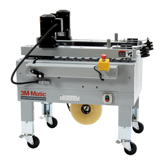
3M-Matic
800ab
Adjustable
Case Sealer
with
AccuGlide
Taping Heads
Serial No.
For reference, record machine serial number here.
3M Masking and Packaging Systems Division
3M Center Bldg. 220-8W-01
St. Paul, MN 55144-1000
TM
Type 39600
TM
II
Important Safety
Information
Read "Important Safeguards",
pages 3-5 and also
operating "Warnings",
page 16 BEFORE
INSTALLING OR
OPERATING THIS
EQUIPMENT.
Spare Parts
It is recommended you
immediately order the
spare parts listed on
page 27. These
parts are expected to
wear through normal use
and should be kept on
hand to minimize
production delays.
"3M-Matic"and "AccuGlide" are Trademarks
of 3M, St. Paul, MN 55144-1000
Litho in U.S.A.
© 3M 1997 44-0009-1910-8(A97.750)
Advertisement
Table of Contents

Related Manuals for 3M 3M-Matic 800ab


Summary of Contents for 3M 3M-Matic 800ab
- Page 1 Serial No. For reference, record machine serial number here. "3M-Matic"and "AccuGlide" are Trademarks 3M Masking and Packaging Systems Division of 3M, St. Paul, MN 55144-1000 Litho in U.S.A. 3M Center Bldg. 220-8W-01 St. Paul, MN 55144-1000...
- Page 2 Minimum billing on parts orders will be $25.00. Replacement part prices available on request. $10.00 restocking charge per invoice on returned parts. Note : Outside the U.S., contact the local 3M subsidiary for parts ordering information. "3M-Matic", "AccuGlide" and “Scotch” are trademarks of 3M Packaging Systems Division 3M, St.
- Page 3 Replacement Parts And Service Information To Our Customers: This is the 3M-Matic™/AccuGlide™/Scotch™ brand equipment you ordered. It has been set up and tested in the factory with "Scotch" brand tapes. If any problems occur when operating this equipment, and you desire a service call, or phone consultation, call, write or Fax the appropriate number listed below.
-
Page 4: Table Of Contents
Instruction Manual 800ab Adjustable Case Sealer, Type 39600 This instruction manual is divided into two sections as follows: Section Includes all information related to installation, operation and parts for the case sealer. Section Includes specific information regarding the AccuGlide™ STD 2 Inch Taping Head. Table of Contents Page Section... - Page 5 Table of Contents (Continued) Page Adjustments ............................. Drive Belt Tension ......................Taping Head Adjustments .................... Special Set-Up Procedure ......................... 23 - 24 Changing Tape Leg Length ................. Case Sealer Frame ..................Taping Head ....................Drive Belt Assembly Height ................. 23 - 24 Disassemble ....................
-
Page 6: Intended Use
Intended Use The intended use of the 3M-Matic 800ab Adjustable Case Sealer with AccuGlide Lower Taping Head is to automatically seal the bottom center seam of regular slotted containers. The case sealer is manually adjustable to a wide range of box sizes (see Box Weight and Size Capacities, page 8). The machine has been designed and tested for use with Scotch brand pressure-sensitive film box sealing tapes. -
Page 7: Equipment Warranty And Limited Remedy
3M’s factory or an authorized service station designated by 3M. A part will be presumed to have become defective after its warranty period unless the part is received or 3M is notified of the problem no later than five (5) calendar days after the warranty period. -
Page 8: Safety Labels
Important Safeguards The "Warning – Hazardous Voltage" label, shown This safety alert symbol identifies in Figure 1-2, is attached to the cover of the important messages in this manual. electrical box. The label warns service personnel to READ AND UNDERSTAND THEM BEFORE unplug the power supply before attempting any INSTALLING OR OPERATING THIS service work on the case sealer. - Page 9 Important Safeguards (Continued) The "Stop" and "Off/On" labels, are attached next The "Operating Notice" label, shown in Figure 1-6, to the switches as shown in Figure 1-4. These is located on top of both drive belt assemblies to labels remind operators and casual personnel of the remind operators of belt adjustment procedures.
- Page 10 Important Safeguards (Continued) The following labels are located on the lower taping The "Tape Threading Label" shown in Figure 1-9, head. Replacement part numbers for these two is attached to the left side of the lower taping head. labels are listed in Section II. This label provides a convenient tape threading diagram.
- Page 11 THIS PAGE IS BLANK...
-
Page 12: Specifications
[8 foot] standard neoprene covered power cord and a grounded plug. 6. Tape Roll Diameter: Contact your 3M Representative for power Up to 405 mm [16 inches] maximum on a requirements not listed above. 76.2 mm [3 inches] diameter core. - Page 13 Specifications (Continued) 9. Box Weight and Size Capacities: Weight Note: The case sealer is designed to Maximum – up to 38.6 kg [85 pounds] accommodate most boxes complying with the 1976 Minimum – contents must support top flaps and FBA and PMMI* voluntary standard "Tolerances for weight must be sufficient to hold bottom flaps Top Opening"...
-
Page 14: Specifications
Specifications (Continued) Machine Dimensions Minimum mm [Inches] 825 [32-1/2] 920 [36-1/4] 940 [37] 460 [18] 610 [24] * 105 [4-3/16] 620 [24-1/2] Maximum mm [Inches] 1220 [48] * 890 [35] * 1270 [50]** * With drive belt assembly in normal position ** With drive belt assembly in upper position (See "Special Set-Up Procedure", page 23) Weight –... - Page 15 THIS PAGE IS BLANK...
-
Page 16: Installation And Set-Up
M6 plain washers and claim immediately with the transportation company M6 locking nuts. See Figure 2-1. and also your 3M Representative. Machine Set-Up Important – Read "Warnings" on page 16, before attempting to set-up the case sealer for operation. - Page 17 Installation and Set-Up (Continued) Check for free action of lower taping head. WARNING – Keep hands/fingers away from tape cut-off knife under orange knife guard. Knife is extremely sharp and can cause severe injury. Push buffing roller into head to check for free, smooth action of taping head.
-
Page 18: Machine Bed Height
Installation and Set-Up (Continued) TAPE LEG LENGTH Use appropriate material handling equipment to remove the machine from the pallet and Taping heads are pre-set to apply 70 mm move it into position. [2-3/4 inch] long tape legs. To change tape legs to 48 mm [2 inch], see "Special Set-Up Whenever the machine is lifted with a fork Procedure –... - Page 19 THIS PAGE IS BLANK...
-
Page 20: Operation
Operation IMPORTANT – Before operating the case sealer read all the "Important Safeguards", pages 3-5 and "Warnings", on page 16 as well as all of the "Operation" instructions. Refer to Figure 3-1 to acquaint yourself with the various components of the case sealer and also see Section II, page 6, for taping head components. -
Page 21: Operation "Warnings
Operation (Continued) WARNINGS 1. Turn electrical supply off and disconnect before servicing taping head or performing any adjustments or maintenance on the machine. 2. Turn electrical supply off when machine is not in use. 3. Before turning drive belts on, be sure no tools or other objects are on the machine bed. 4. -
Page 22: Box Size Set-Up
Operation (Continued) Box Size Set-Up 1. ADJUST DRIVE BELTS (Figure 3-2) Place a product filled box on infeed conveyor bed with top flaps folded as shown and manually move box forward to contact lower taping head applying roller. Turn drive belt adjustment crank to position both side drive belts against sides of box. -
Page 23: Box Sealing
Operation (Continued) Box Sealing 1. Feed boxes to machine at minimum 455 mm [18 inch] intervals. 2. Turn electrical supply "Off" when machine is not in use. 3. Reload and thread tape as necessary. 4. Be sure machine is cleaned and lubricated according to recommendations in "Maintenance"... -
Page 24: Maintenance
Maintenance The case sealer has been designed for long, Figure 4-1 illustrates the frame points which should trouble-free service. The machine will perform best be lubricated every 250 hours of operation. when it receives routine maintenance and cleaning. Lubricate the rotating and pivoting points, noted by Machine components that fail or wear excessively the arrows, ( ) with SAE #30 non-detergent oil. -
Page 25: Circuit Breaker
Circuit Breaker Drive Belts The case sealer is equipped with a circuit breaker Note – 3M recommends the replacement of which trips if the motors are overloaded. Located drive belts in pairs, especially if belts are inside the electrical enclosure on the side of the unevenly worn. - Page 26 Maintenance (Continued) Figure 4-3 – Box Drive Assembly, Infeed End 5. Install the new belt around drive rollers and 6. To set drive belt tension, turn adjustment screws insert new pin. Pin must not extend beyond (G) equally on both the upper and lower tension edge of belt.
-
Page 27: Adjustments
Adjustments WARNING – Turn off electrical power supply and disconnect power cord from electrical supply before beginning adjustments. If power cord is not disconnected, severe injury to personnel could result. Drive Belt Tension Tension adjustment of the drive belts may be required during normal operation. Belt tension must be adequate to positively move the box through the machine and they should run fully on the surface of the pulleys at each end of the frame. -
Page 28: Special Set-Up Procedure
Special Set-Up Procedure Drive Belt Assembly Height WARNING – Turn off electrical power and disconnect power cord from The drive belt assemblies can be raised 48 mm electrical supply before beginning special [2 inches] to provide better conveying of tall boxes. set-up procedure. -
Page 29: Reassemble
Special Set-Up Procedure (Continued) REASSEMBLE – Figure 5-2 4. Reassemble the spacer (C) onto the front and rear arm assembly pivots first. 5. Install the belt drive assembly (D) onto the pivots and secure with the cap washers (B) and screws (A). -
Page 30: Troubleshooting
Troubleshooting The Troubleshooting Guide lists some possible machine problems, causes and corrections. Also see Section II, "Troubleshooting", pages 15 and 16 for taping head problems. Troubleshooting Guide Cause Problem Correction Narrow boxes Drive belts do not convey boxes Check machine specifications. Boxes are narrower than recommended, causing slippage and premature belt wear. -
Page 31: Electrical Diagram
Electrical Diagram WARNING – Turn off electrical power supply and disconnect power cord from electrical supply before beginning service. If power cord is not disconnected, personnel could be exposed to dangerous voltages. Severe injury or equipment damage could result. Figure 7 – Electrical Diagram... -
Page 32: Spare Parts/Tools/Label Kit
Spare Parts/Tools Spare Parts The following parts periodically require replacement due to normal wear. They should be ordered immediately and kept on hand to keep the case sealer in production. 800ab Adjustable Case Sealer, Type 39600 Section/Ref. No. Part Number Description II/2880-15 78-8057-6179-4... -
Page 33: Options/Accessories
Options/Accessories For additional information on the options/accessories listed below, contact your 3M Representative. Part Number Option/Accessory 78-8052-6553-1 Box Hold Down Attachment, Model 18500 78-8069-3983-7 Caster Kit Attachment 78-8069-3924-1 Conveyor Extension Attachment 78-8069-3926-6 Low Tape Sensor Kit 78-8079-5560-0 Tape Application Sensor Kit... -
Page 34: Replacement Parts Illustrations And Parts Lists
4. Refer to the first page of this instruction manual for replacement parts ordering information. IMPORTANT – Not all the parts listed are normally stocked items. Some parts or assemblies shown are available only on a special order basis. Contact 3M/Tape Dispenser Parts to confirm item availability. - Page 35 THIS PAGE IS BLANK...
- Page 36 800ab Adjustable Case Sealer W/AccuGlide™ STD (2 Inch) Taping Head 800ab Assembly...
- Page 37 800ab Adjustable Case Sealer Figure 3419...
- Page 38 Figure 3419 Ref. No. 3M Part No. Description 3419-1 78-8070-1565-2 Tape Drum Bracket Assembly 3419-2 78-8070-1395-4 Bracket – Bushing Assembly 3419-3 78-8017-9169-6 Nut – M18 x 1 3419-4 78-8060-8474-1 Tape Drum Assembly – 2 Inch Head 3419-5 78-8076-4519-3 Shaft – Tape Drum...
- Page 39 800ab Adjustable Case Sealer Figure 6163/1 of 2...
- Page 40 Figure 6163 (page 1 of 2) Ref. No. 3M Part No. Description 6163-1 78-8100-1229-0 Shaft Assembly – Drive R/H 6163-2 78-8100-1230-8 Shaft Assembly – Drive L/H 6163-3 78-8076-5401-3 Block – Upper 6163-4 78-8076-5402-1 Block – Lower 6163-5 78-8076-5403-9 Nut – Block, R/H...
- Page 41 800ab Adjustable Case Sealer Figure 6163/2 of 2...
- Page 42 Figure 6163 (page 2 of 2) Ref. No. 3M Part No. Description 6163-28 78-8017-9079-7 Ring – Snap For 15 mm Shaft 6163-29 78-8076-5418-7 Support – Screw 6163-30 26-1003-7949-9 Screw – Soc Hd Hex Soc, M5 x 12 6163-31 78-8005-5741-1 Washer – Plain M5...
- Page 43 800ab Adjustable Case Sealer Figure 6174/1 of 2...
- Page 44 Figure 6174 ( Page 1 of 2 Ref. No. 3M Part No. Description 6174-1 78-8076-5380-9 Bed – Conveyor 6174-2 78-8076-5381-7 Leg Assembly – Inner, W/Stop 6174-3 78-8076-5382-5 Leg – Inner 6174-4 78-8060-8480-8 Pad – Foot 6174-5 78-8055-0867-4 Screw – Hex Hd, M8 x 30...
- Page 45 800ab Adjustable Case Sealer Figure 6174/2 of 2...
- Page 46 Figure 6174 ( Page 2 of 2 Ref. No. 3M Part No. Description 6174-27 78-8060-8485-7 Roller 6174-28 78-8032-0375-7 Screw – Hex Hd M6 x 16 6174-29 26-1000-0010-3 Washer – Flat M6 6174-30 26-1003-7957-2 Screw – Soc Hd Hex Hd M6 x 16...
- Page 47 800ab Adjustable Case Sealer Figure 6175/1 of 2...
- Page 48 Figure 6175 (page 1 of 2) Ref. No. 3M Part No. Description 6175-1 78-8100-1223-3 Side Drive Assembly – R/H W/O Motor 6175-2 78-8100-1224-1 Side Drive Assembly – L/H W/O Motor 6175-3 78-8100-1207-6 Guide – Lower, R/H 6175-4 78-8100-1208-4 Guide – Lower, L/H...
- Page 49 800ab Adjustable Case Sealer Figure 6175/2 of 2...
- Page 50 Figure 6175 (page 2 of 2) Ref. No. 3M Part No. Description 6175-35 78-8076-5443-5 Pulley Assembly – Idler 6175-36 78-8055-0660-3 Roller – Idler 6175-37 78-8076-5444-3 Shaft – Idler Pulley 6175-38 12-7997-0272-0 E-Ring – M-25 6175-39 78-8076-5445-0 Tensioning – Belt 6175-40 78-8076-5486-4 Screw –...
- Page 51 800ab Adjustable Case Sealer Figure 6176...
- Page 52 Figure 6176 Ref. No. 3M Part No. Description 6176-1 78-8100-1225-8 Slide Compression Roller – R/H 6176-2 78-8100-1226-6 Slide Compression Roller – L/H 6176-3 78-8113-6984-8 Bracket – Roller, R/H, W/English Language Label 6176-4 78-8113-6985-5 Bracket – Roller, L/H, W/English Language Label...
- Page 53 800ab Adjustable Case Sealer Figure 6177...
- Page 54 Figure 6177 Ref. No. 3M Part No. Description 6177-1 78-8094-6379-3 Support Box 6177-2 78-8113-6759-4 Box – W/English Language Label 6177-3 78-8094-6381-9 Screw – Soc Hd, Hex Hd, M4 x 15 6177-4 78-8005-5740-3 Washer – Plain, 4 mm 6177-5 26-1003-6914-4 Nut – Plastic Insert, M4...
- Page 55 800ab Adjustable Case Sealer Safety and Information Labels...
- Page 56 A label kit, part number 78-8113-6745-3, is available as a stock item. It contains all the safety and information labels used on the case sealer, or labels can be ordered separately from the following list. Ref. No. 3M Part No. Description Qty.
Need help?
Do you have a question about the 3M-Matic 800ab and is the answer not in the manual?
Questions and answers