
Subscribe to Our Youtube Channel
Related Manuals for Zodiac PX50 MD12


Summary of Contents for Zodiac PX50 MD12
- Page 1 PX50 Instructions for installation and use - English Heat pump Translation of the original instructions in French More documents on: www.zodiac.com H0686900_REVB - 2020/03...
- Page 3 WARNINGS This symbol shows that This symbol shows that this information is available such appliance uses R32, a low as the Operating Manual or burning velocity refrigerant. Installation Manual. This symbol shows that service This symbol shows that the personnel should be handling Operation Manual should be read this equipment with reference to carefully.
- Page 4 for operating the appliance. • Deactivating, eliminating or by-passing any of the safety mechanisms integrated into the appliance shall automatically void the warranty, in addition to the use of spare parts manufactured by unauthorised third-party manufacturers. • Do not spray insecticide or any other chemical (flammable or non-flammable) in the direction of the appliance, as this may damage the body and cause a fire.
- Page 5 shows no signs of damage or rust. • For any component or sub-assembly containing a battery: do not recharge or dismantle the battery, or throw it into a fire. Do not expose it to high temperatures or direct sunlight. • In stormy weather, disconnect the appliance from the power supply to prevent it from suffering lightning damage.
- Page 6 MAINTENANCE: WARNINGS CONCERNING APPLIANCES CONTAINING R32 REFRIGERANT Area check • Before starting work on systems containing flammable refrigerants, safety checks must be carried out to guarantee a minimal ignition risk. Work procedure • The work must be carried out according to a controlled procedure in order to reduce the risks of releasing a flammable gas or vapour while working.
- Page 7 - the markings on the equipment must remain visible and legible; any illegible markings or signs must be rectified; - the hoses or components of the cooling circuit are installed in a position where they are unlikely to be exposed to any substance capable of corroding the components containing refrigerant, unless the components are made from materials that are typically corrosion-proof or correctly protected from such corrosion.
- Page 8 Wiring • Check that the wiring shows no signs of wear, corrosion, excessive pressure, vibration, cutting edges or any other detrimental environmental effect. The check must also take into account the effects of ageing or continuous vibrations caused by sources such as compressors or fans. Detection of flammable refrigerant •...
- Page 9 refrigerants when using charging equipment. Hoses or lines must be as short as possible to reduce the quantity of refrigerant contained therein. - Cylinders must be kept in an appropriate position, in accordance with the instructions. - Check that the cooling system is grounded before charging the system with refrigerant.
- Page 10 - use dry nitrogen or the mixture of nitrogen and refrigerant indicated on the information plate, - the test pressure for both the high and low pressure circuits must not exceed 42 bar in cases where the appliance is equipped with the optional pressure gauge. •...
- Page 11 be used to accelerate this process. This operation can be carried out safely once all liquids within the system have been drained. RECYCLING This symbol means that your appliance must not be thrown into a normal bin. It will be selectively collected for the purpose of reuse, recycling or transformation.
-
Page 12: Table Of Contents
The distribution or modification of this document in any way is prohibited, without prior • authorisation from Zodiac®. Zodiac® is constantly developing its products to improve their quality. The information • contained herein may therefore be modified without notice. CONTENTS ❶... -
Page 13: ❶ Installation
❶ Installation 1.1 I Selecting the location • When the appliance is installed and protected by a residual current device (RCD) with a maximum amperage of 30 mA, it should be installed at a distance of at least 2 metres from the edge of the pool. -
Page 14: I Hydraulic Connections
1.2 I Hydraulic connections • The device will be connected with a Ø50 PVC pipe, using the connectors supplied (see § “5.1 I Description”), to the pool's filtration circuit, after the filter and before the water treatment system. • Respect the direction of hydraulic connection. •... -
Page 15: I Accessing The Electrical Terminal Blocks
1.3 I Accessing the electrical terminal blocks Unscrew the 3 screws on the Pass the cables through the cable technical access door at the rear of Remove the technical access door. glands on the technical access door. the appliance. 1.4 I Power supply connections •... -
Page 16: I Option Connections
1.5 I Option connections Connecting the "Heating priority" and "remote control" options: • Before any work inside the appliance, you must cut the appliance’s electricity supply as there is a risk of electric shock which may cause material damage, serious injury or even death. •... -
Page 17: ❷ Use
❷ Use 2.1 I Operating principle 2.1.1 General operation Your heat pump uses the calories (heat) in the air to heat up your pool's water. The process to heat your pool's water to the temperature you want may take a few days as it depends on the weather conditions, the heat pump's power and the difference between the water temperature and the temperature you want. -
Page 18: I Operation
Description Steady Flashing Operating in "HEATING" "HEATING" mode Disabled mode Operating in "COOL- "COOLING" mode Disabled ING" mode "HEATING & COOLING" Operating in "HEATING Disabled mode & COOLING" mode "BOOST" mode Operating at full power "BOOST" mode Disabled activated in "SMART" mode Operating at medium "SMART"... -
Page 19: I User Functions
After the start-up steps for your heat pump: • Shut down the water circulation temporarily (by stopping the filtration or closing valve B or C) to check that your appliance stops after a few seconds (via the activation of the flow switch). •... - Page 20 2.4.4 "BOOST", "SMART" and "SILENCE" mode The PX50 heat pump can adapt its power to suit the pool temperature and weather conditions. In doing so, it obtains maximal energy efficiency at a very low noise level. Silence Boost Power "BOOST" mode "SMART"...
-
Page 21: ❸ Maintenance
• Clean the outside of the appliance using a solvent-free product; a specific "PAC NET" cleaning kit is available as an accessory in the Zodiac® catalogue for this purpose (see § “5.1 I Description”). 3.2.2 Maintenance to be carried out by a qualified technician •... -
Page 22: ❹ Troubleshooting
❹ Troubleshooting • If a problem occurs, before you contact your retailer, please carry out these few simple checks using the following tables. • If the problem continues, contact your retailer. • : Actions to be performed by a qualified technician only 4.1 I Appliance behaviour •... -
Page 23: I Error Code Display
4.2 I Error code display Display Possible causes Solutions PP01 Sensor disconnected or out of order. Reconnect or replace the sensor. Faulty inlet water temperature sensor PP02 Sensor disconnected or out of order. Reconnect or replace the sensor. Faulty outlet water temperature sensor PP03 Sensor disconnected or out of order. - Page 24 In heating mode, temperature Check that the flow rate is sufficient. overheating error. EE04 Faulty flow switch. In heating mode, temperature Replace the flow switch. overheating error Abnormal d2-TH5 sensor reading. Replace the d2-TH5 sensor. Check for the presence of gas Insufficient refrigerant.
- Page 25 The data is incorrect. Check the compressor. The water flow rate is insufficient. Check the water flow rate. EE13 Electrical protection The voltage is unstable. Check the power supply voltages. PFC failure. The power supply is incorrect. EE14 Check the power board. Abnormal IPM module operating The fan motor is defective or the Check the fan speed...
- Page 26 EE24 Ambient temperature or input water Check and replace the printed Ambient temperature or printed circuit temperature too low. circuit board. board The compressor operates with 1 or 2 EE25 Check the wiring. Compressor power error phases. Switch to heating/cooling mode to check inversion of the valve.
-
Page 27: I Wiring Diagrams
4.3 I Wiring diagrams 4.3.1 PX50 MD3 - MD4 - MD5 - MD6 - MD7... - Page 28 4.3.2 PX50 MD9...
- Page 29 4.3.3 PX50 MD11 - MD12...
- Page 30 4.3.4 PX50 TD11 - TD12...
-
Page 31: ❺ Specifications
❺ Specifications 5.1 I Description PX50 Ø50 PVC connectors x2 Anti-vibration pads x4 Winterising cover Heating priority Remote control kit Condensate drainage connector x2 Hose x2 PAC NET (cleaning product) : Included : Available as an accessory... -
Page 32: I Technical Specifications
5.2 I Technical specifications PX50 MD11 TD11 MD12 TD12 Heating: from -12°C to 43°C/Cooling: from 15°C to 43°C Operating temperatures water Heating: from 6°C to 41°C/Cooling: from 6°C to 35°C Power output (max- 10.5 - 13.5 - 16.5 - 19.5 - 9 - 1.9 25 - 4.5 31 - 5.6... -
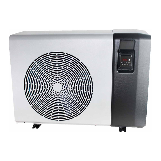
Page 33: I Dimensions And Marking
5.3 I Dimensions and marking MD3 - MD4 - MD5 - MD6 - MD7 - MD9 MD11 - MD12 - TD11 - TD12 Front : Grid : User interface : Pool water inlet : Pool water outlet : Evaporator Side Model MD4 - MD5 - MD7 - MD9... - Page 36 Pour plus d’informations, enregistrement produit et support client : For more information, product registration and customer support: www.zodiac.com ©2020 Zodiac Pool Systems LLC. All rights reserved. ZODIAC® is a registered trademark of Zodiac International, S.A.S.U., used under license. All other trademarks are the property of their respective owners.
Need help?
Do you have a question about the PX50 MD12 and is the answer not in the manual?
Questions and answers