ICT Protege GX, PRT-CTRL-DIN - Integrated System Controller Quick Start Guide
- Troubleshooting manual (38 pages)
Advertisement
Introducttion
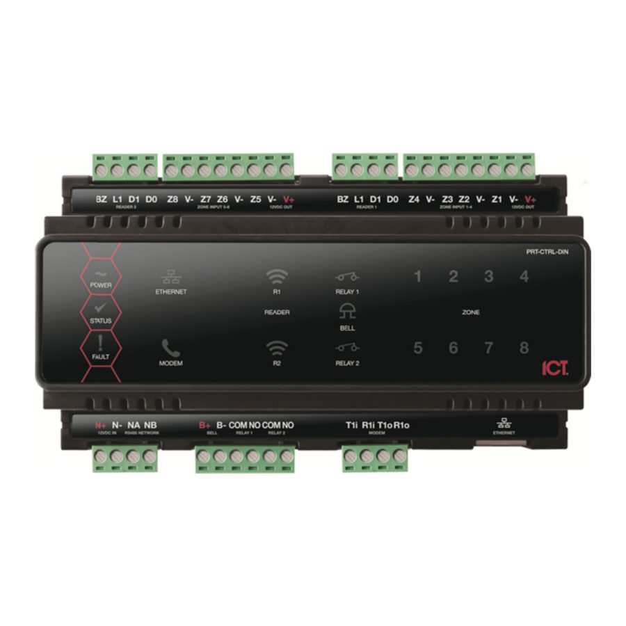
Thank you for purchasing the Protege GX DIN Rail Integrated System Controller by Integrated Control Technology. The Controller is the central processing unit of the Protege System. It communicates with all system modules, stores all configuration and transaction information, processes all system communication, and reports alarms and system activity to a monitoring station or remote computer.
When receiving the GX Integrated System Controller you should find the kit contains the items listed below. Please note that if you do not have the correct contents, you should contact your distributor immediately.
- Protege GX DIN Rail Integrated System Controller
- 18 1K ohm resistors
- 1 330 Ohm EOL Termination Resistor
- 1 Diode 1N4007 1A 400V (Axial)
- DIN Rail Mounting Strip
For more information on the Protege GX DIN Rail Integrated System Controller and other Integrated Control Technology products please login to www.incontrol.co.nz.
Power Requirements

Example Power Supply Connection
The Protege GX Integrated System Controller is supplied by a 12V DC power supply connected to the N+ and N- terminals. It does not contain internal regulation or isolation. It is recommended that an ICT PRT-PSU-DIN is used for this purpose. In a small installation this same power supply can be used to supply the module network as well, so long as the maximum load of the power supply is not exceeded. If using the PRT-PSU-DIN module, it can support battery backup and can be connected to the module network to provide a monitored supply. Please refer to the PRT-PSU-DIN installation manual for specific details of the connections.
In larger installations, the power supply may need to be split to allow for load sharing between several supplies.

Example multiple PSU Connection
Card Reader Connection

Card Reader Connection
The following diagram shows the connection of a standard Wiegand Reader with the GX Integrated System Controller controlling an Access Door in Entry or Exit mode. The Controller does not support dual LED reader mode and readers must be configured for single LED mode. Refer to your card reader documentation for further details.
Door Contact Connection

Door Contact Connection
The Protege GX Integrated System Controller allows the connection of up to 4 contacts for monitoring and controlling access control doors. Each input on the Controller can be used for the door function that is automatically assigned and as a normal input on the system. The following example shows the connection of a normally closed door position monitoring contact to monitor the Open, Closed, Forced and Alarm conditions of the door.
| Input | Function | Default Setting |
| Input 1 | Door Contact, Por rt 1 | Door Contact, Port 1 |
| Input 2 | REX Input, Port 1 | REX Input, Po ort 1 |
| Input 3 | Bond Sense, Port 1 | General Purp pose Input |
| Input 4 | REN Input, Port 1 | General Purp pose Input |
| Input 5 | Door Contact, Por rt 2 | Door Contact, Port 2 |
| Input 6 | REX Input, Port 2 | REX Input, Po ort 2 |
| Input 7 | Bond Sense, Port 2 | General Purp pose Input |
| Input 8 | REN Input, Port 2 | General Purp pose Input |
Lock Output Connection

Lock Output Connection
The Protege GX Integrated System Controller provides a connection for one electric strike lock with full monitoring of the lock circuit for tamper and over current/fuse blown conditions. The door lock monitoring can be disabled if it is not required.
The lock output is shared with the bell/siren functions. You can select another output for the lock control (Relay 1 (CP001:03) or Relay 2 (CP001:04)) if the bell/siren function is required. To use the lock output in conjunction with the onboard reader module, the Lock output for the door associated with the reader port must be configured to be the desired lock output on the controller. This is not configured by default.
Encrypted Module Network

Standard Communication Connection
The Protege GX Integrated System Controller incorporates encrypted RS-485 communications technology.
Always connect the Controller's NA and NB terminals to the NA and NB terminals of the expansion devices and keypads. The N+ and N- must connect to a 12V power supply source capable of supplying the peak current drawn by all modules. If a shielded cable is used, the shield must be connected at only one end of the cable. DO NOT connect a shield at both ends.
Ethernet Interface
The communication between the Protege System and the Protege GX Integrated System Controller uses a 10/100 Ethernet network operating the TCP/IP protocol suite. The IP address of the Controller can be configured using the LCD Keypad terminal or via the built in web interface. The default IP address is set to a static IP address of 192.168.1.2 with a subnet mask of 255.255.255.0.
Telephone Dialer

Telephone Line Connection
The GX Integrated System Controller provides the ability to communicate alarms and upload information to remote systems using the onboard 2400bps modem. The telephone line can be connected directly to the Controller using the onboard telephone connection terminals.
Inputs

EOL Resistor Input Configuration

No EOL Resistor Input Configuration
The Protege GX Integrated System Controller can monitor the state of up to 8 onboard inputs such as magnetic contacts, motion detectors and temperature sensors. Devices connected to these inputs can be installed to a maximum distance of 300m (1000ft) from the Controller when using 22 AWG. The Controller supports normally opened and normally closed configurations with or without EOL resistors.
Technical Specifications
| Operating Voltage | 12V DC +- 10% |
| Operating Current | 120mA (Typical) |
| DC Output (Auxiliary) | 0.7A (Typical) Electronic Shutdown at 1.1A |
| Bell DC Output (Continuous) | 8 Ohm 30W Siren or 1.1A (Typical) |
| Bell DC Output (Inrush) | 1500mA |
| Total Combined Current | 3.4A (Max) |
| Electronic Disconnection | 9.0VDC |
| Communication (Ethernet) | 1 10/100Mbps Ethernet Communication Link |
| Communication (Serial) | 1 RS-485 Communication Interface Port |
| Communication (Modem) | 1 2400bps Modem Communication |
| Readers (Standard Mode) | 2 Wiegand or clock data readers providing one Entry/Exit Door or two Entry/Exit only Doors |
| Readers (Multiplex-reader Mode) | 4 Wiegand Readers (connected in Multiplex Reader mode) providing any combination of Entry or Exit for two Doors |
| Inputs (System Inputs) | 8 High Security Monitored Inputs |
| Outputs | 4 50mA (Max) Open Collector Output for reader LED and beeper or general functions |
| Relay Outputs | 2 FORM A Relays - 7A max |
| Operating Temperature | 0˚ to 49˚C (32˚ to 122˚F) |
| Storage Temperature | -10˚ to 85˚C (14˚ to 185˚F) |
| Humidity | 0% to 85% non condensing, indoor use only (Relative Humidity) |
| Dimensions (L x W x H) | 156 x 90 x 60mm (6.14 x 3.54 x 2.36") |
| Weight | 376g (13.26oz) |
| The size of conductor used for the supply of all power to the Protege GX Integrated System Controller should be adequate in size to prevent voltage drop at the terminals of no more than 5% of the rated voltage. Specifications are subject to change without notice, please visit www.incontrol.co.nz for updated information. | |
Integrated Control Technology Limited
11 Canaveral Drive, Albany, North Shore City 0632, Auckland, New Zealand
P.O. Box 302-340, North Harbour, Auckland, New Zealand
Phone: +64 (9) 476 7124
Fax: +64 (9) 476 7128
Email: support@incontrol.co.nz
www.incontrol.co.nz

Documents / Resources
References
Download manual
Here you can download full pdf version of manual, it may contain additional safety instructions, warranty information, FCC rules, etc.
Download ICT Protege GX, PRT-CTRL-DIN - Integrated System Controller Quick Start Guide
Advertisement


Need help?
Do you have a question about the Protege GX and is the answer not in the manual?
Questions and answers