ICT PRT-WX-DIN-1D Installation Manual
Single door controller
Hide thumbs
Also See for PRT-WX-DIN-1D:
- Programming reference manual (153 pages) ,
- Configuration manual (41 pages) ,
- Installation manual (61 pages)
Table of Contents
Advertisement
Quick Links
Advertisement
Table of Contents

Subscribe to Our Youtube Channel
Related Manuals for ICT PRT-WX-DIN-1D


Summary of Contents for ICT PRT-WX-DIN-1D
- Page 1 PRT-WX-DIN-1D Protege WX DIN Rail Single Door Controller Installation Manual...
- Page 2 Protege® Logo are registered trademarks of Integrated Control Technology Limited. All other brand or product names are trademarks or registered trademarks of their respective holders. Copyright © Integrated Control Technology Limited 2003-2022. All rights reserved. Last Published: 17-Jun-22 4:19 PM PRT-WX-DIN-1D | Protege WX DIN Rail Single Door Controller | Installation Manual...
-
Page 3: Table Of Contents
EOL Resistor Value Options Duplex Inputs Trouble Inputs Outputs Hardware Configuration Configuring a Controller via the Web Interface Setting the IP Address from a Keypad Temporarily Defaulting the IP Address PRT-WX-DIN-1D | Protege WX DIN Rail Single Door Controller | Installation Manual... - Page 4 Peripheral Devices Testing Frequency Recommended Routine Maintenance Procedures European Standards UK Conformity Assessment Mark UK PD 6662:2017 and BS 8243 FCC Compliance Statements Industry Canada Statement Disclaimer and Warranty PRT-WX-DIN-1D | Protege WX DIN Rail Single Door Controller | Installation Manual...
-
Page 5: Introduction
Single Door Controller Editions There are two editions of the PRT-WX-DIN-1D Controller: ⦁ The PRT-WX-DIN-1D can be supplied power from a 12V DC power supply connected to the N+ and N- terminals. ⦁ The PRT-WX-DIN-1D-POE can be supplied power from a 12V DC power supply connected to the N+ and N- terminals OR from a power over ethernet (PoE) router via the onboard ethernet terminal. -
Page 6: Installation Requirements
Installation Requirements This equipment is to be installed in accordance with: The product installation instructions ⦁ AS/NZS 2201.1 Intruder Alarm Systems ⦁ The Local Authority Having Jurisdiction (AHJ) ⦁ PRT-WX-DIN-1D | Protege WX DIN Rail Single Door Controller | Installation Manual... -
Page 7: Grounding Requirements
(RS-485 N+, N-, NA, NB) DIN Rail Enclosure Additional DIN Rail Enclosure(s) Controller Reader Expander Dialer’s Earth Ground Connection Input Expander Power Supply Output Expander AC Mains Wiring Earth Ground Link Connection PRT-WX-DIN-1D | Protege WX DIN Rail Single Door Controller | Installation Manual... - Page 8 Note that the DIN rail enclosure earth terminal is connected to the power supply V- terminal. There must be only one single earth grounding point per system. PRT-WX-DIN-1D | Protege WX DIN Rail Single Door Controller | Installation Manual...
-
Page 9: Mounting
A Protege DIN rail module can be removed from the DIN rail mount using the following steps: Insert a flat blade screwdriver into the hole in the module tab clip. Lever the tab outwards and rotate the unit off the DIN rail mount. PRT-WX-DIN-1D | Protege WX DIN Rail Single Door Controller | Installation Manual... -
Page 10: Connections
A battery backup must be connected to the module network to provide a monitored supply. The battery plays an important role in power conditioning and provides a continuous source of power in the event of a power outage. Example 2A Power Supply Connection: PRT-WX-DIN-1D | Protege WX DIN Rail Single Door Controller | Installation Manual... - Page 11 When using multiple power supplies it is important to ensure that all ground connections (V-) are connected between all power supplies and that no power connections (V+) are connected between any power supplies. PRT-WX-DIN-1D | Protege WX DIN Rail Single Door Controller | Installation Manual...
-
Page 12: Auxiliary Outputs
Integrated Control Technology power supply or a 12V DC supply. Please refer to the values outlined in the Technical Specifications below for more details. PRT-WX-DIN-1D | Protege WX DIN Rail Single Door Controller | Installation Manual... -
Page 13: Encrypted Module Network
CAT5e / CAT6 are also supported for data transmission when using ground in the same cable (to a maximum length of 100m (328ft)) Warning: Unused wires in the cable must not be used to carry power to other devices. PRT-WX-DIN-1D | Protege WX DIN Rail Single Door Controller | Installation Manual... -
Page 14: End Of Line (Eol) Resistors
Battery fault conditions will activate the battery trouble input associated with the address assigned to the controller. PRT-WX-DIN-1D | Protege WX DIN Rail Single Door Controller | Installation Manual... -
Page 15: Ethernet 10/100 Network Interface
Ethernet 10/100 Switch Hub Connection: Temporary direct connections can be used for onsite programming by using a standard ethernet cable. Ethernet 10/100 Direct Connection: PRT-WX-DIN-1D | Protege WX DIN Rail Single Door Controller | Installation Manual... -
Page 16: Door Access Control
Do not terminate the reader shield wire inside the reader. Note: The reader and cable shield wires must be joined at the reader pigtail splice for all MIFARE capable ICT card readers. Older readers which are internally grounded and third-party readers do not require the shield wires to be joined. -
Page 17: Rs-485 Reader Connection (Entry Only)
NA and NB terminals of the reader and a second 330 ohm EOL resistor must then be inserted between the source NA and NB terminals at the other end of the wiring. PRT-WX-DIN-1D | Protege WX DIN Rail Single Door Controller | Installation Manual... -
Page 18: Door Contact Connection
To use the lock output in conjunction with the onboard reader, the lock output for the door associated with the reader port must be configured to be the desired lock output on the controller. This is not configured by default. Typical Lock Output Connection: PRT-WX-DIN-1D | Protege WX DIN Rail Single Door Controller | Installation Manual... -
Page 19: Programming The Onboard Reader
REX Input, Port 1 REX Input, Port 1 The controller's onboard reader port supports an RS-485 reader interface, allowing ICT RS485 readers to be configured. This can be set in the Expanders | Reader Expanders menu. PRT-WX-DIN-1D | Protege WX DIN Rail Single Door Controller | Installation Manual... -
Page 20: Inputs
Protege field modules. Value 1 Value 2 Monitored Status No Resistor No Resistor Open, Closed Open, Closed, Tamper, Short Open, Closed, Tamper, Short Open, Closed, Tamper, Short PRT-WX-DIN-1D | Protege WX DIN Rail Single Door Controller | Installation Manual... -
Page 21: Duplex Inputs
Input Address Position Resistor Enabling duplex inputs will not change the programming of any existing inputs. These must be reprogrammed or rewired to match the new addressing scheme. PRT-WX-DIN-1D | Protege WX DIN Rail Single Door Controller | Installation Manual... -
Page 22: Trouble Inputs
Hardware Fault System CP001:29 System restarted Hardware Fault System CP001:30 PoE Connection Lost (PoE model only) Power Fault General CP001:31 Output Over-Current Failure (PoE model only) Power Fault General PRT-WX-DIN-1D | Protege WX DIN Rail Single Door Controller | Installation Manual... -
Page 23: Outputs
This output can be used to activate larger relays, sounders, lights, locks etc. Example Relay Connection: Warning: The relay outputs can switch to a maximum capacity of 7A. Exceeding this amount will damage the output. PRT-WX-DIN-1D | Protege WX DIN Rail Single Door Controller | Installation Manual... -
Page 24: Hardware Configuration
[Enter]. You must then restart the controller, either through the menu [4], [2], [2] or by cycling the power, for the settings to take effect. PRT-WX-DIN-1D | Protege WX DIN Rail Single Door Controller | Installation Manual... -
Page 25: Temporarily Defaulting The Ip Address
Remember to change the subnet of your PC or laptop to match the subnet of the controller. Remove the wire link(s) and power cycle the controller again. You can now connect to the controller using the configured IP address. PRT-WX-DIN-1D | Protege WX DIN Rail Single Door Controller | Installation Manual... -
Page 26: Defaulting A Controller
After defaulting a controller a number of essential steps will need to be performed to resume normal operation. Not all of the following steps will necessarily be required, depending on your site configuration: PRT-WX-DIN-1D | Protege WX DIN Rail Single Door Controller | Installation Manual... - Page 27 Reset the controller's IP address to its previous value. Reconfigure any additional network settings. Reinstall previously installed custom HTTPS certificates. Restore any other system settings as required by your site configuration. PRT-WX-DIN-1D | Protege WX DIN Rail Single Door Controller | Installation Manual...
-
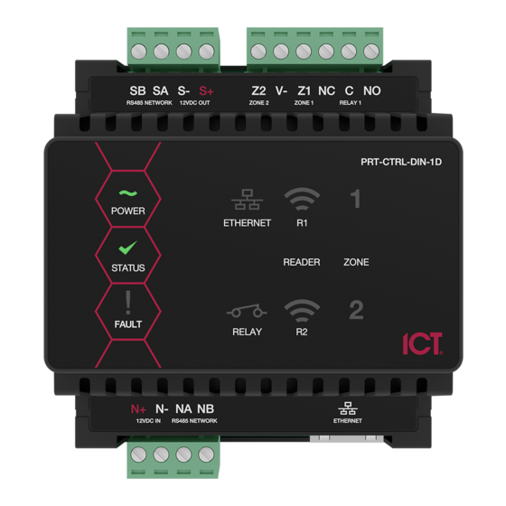
Page 28: Led Indicators
PoE model only The PoE power indicator shows the status of the PoE connection. State Description On (green) PoE+ connection applied Flashing (green) PoE connection applied No PoE connection applied PRT-WX-DIN-1D | Protege WX DIN Rail Single Door Controller | Installation Manual... -
Page 29: Battery Indicator
A LONG flash (>1 second) indicates that the unit has read the data and the format was correct (red) Relay Indicator The relay indicator shows the status of the lock output relay. State Description On (red) Relay output is ON Relay output is OFF PRT-WX-DIN-1D | Protege WX DIN Rail Single Door Controller | Installation Manual... -
Page 30: Input Indicators
Input is in an open state Constantly on (green) Input is in a closed state Continuous flash (red) Input is in a tamper state Continuous flash (green) Input is in a short state PRT-WX-DIN-1D | Protege WX DIN Rail Single Door Controller | Installation Manual... -
Page 31: Mechanical Diagram
Mechanical Diagram The mechanical diagram shown below outlines the essential details needed to help ensure the correct installation of the controller. PRT-WX-DIN-1D | Protege WX DIN Rail Single Door Controller | Installation Manual... -
Page 32: Mechanical Layout
The mechanical layout shown below outlines the essential details needed to help ensure correct installation and mounting. All measurements are shown in millimeters. 78.40 Front 78.40 39.20 39.20 Back 67.18 PRT-WX-DIN-1D | Protege WX DIN Rail Single Door Controller | Installation Manual... -
Page 33: Technical Specifications
Dimensions (L x W x H) 78 x 90 x 60mm (3.07 x 3.54 x 2.36") Net Weight 170g (6oz) 210g (7.4oz) Gross Weight 230g (8.1oz) 310g (10.9oz) Operating Conditions PRT-WX-DIN-1D | Protege WX DIN Rail Single Door Controller | Installation Manual... - Page 34 N+ N- input terminals, and the maximum current is governed by the trip level of these fuses. The ICT implementation of OSDP conforms to a subset of the OSDP functionality. For specifications and reader configuration, refer to Application Note 254: Configuring OSDP Readers, available from the ICT website.
-
Page 35: New Zealand And Australia
In contrast, sites where automated testing functions have been implemented may find that annual maintenance visits are adequate. PRT-WX-DIN-1D | Protege WX DIN Rail Single Door Controller | Installation Manual... -
Page 36: Recommended Routine Maintenance Procedures
Note: When the mains power is restored following an AC fail condition, charge voltage the battery charge voltage may fluctuate between 10.0 - 13.8 VDC while the battery is recharging. PRT-WX-DIN-1D | Protege WX DIN Rail Single Door Controller | Installation Manual... - Page 37 Record and report any discrepancies. Special testing equipment and procedures may be required for smoke, heat, seismic glass-break and other detectors. PRT-WX-DIN-1D | Protege WX DIN Rail Single Door Controller | Installation Manual...
- Page 38 Record these in the maintenance sheets modifications and report. At the conclusion of Obtain client sign Obtain the signature of the client or the client's representative on each maintenance the maintenance record. visit PRT-WX-DIN-1D | Protege WX DIN Rail Single Door Controller | Installation Manual...
-
Page 39: European Standards
SP6 (LAN – Ethernet) and DP1 (LAN – Ethernet + USB-4G modem) Tests EMC (operational) according to EN 55032:2015 Radiated disturbance EN 55032:2015 Power frequency magnetic field immunity tests (EN 61000-4-8) PRT-WX-DIN-1D | Protege WX DIN Rail Single Door Controller | Installation Manual... - Page 40 ATTACK, comply with the EN 50131 standards. Tamper protection against removal of the cover as well as removal from mounting is provided by tamper switch. Warning: Enclosures supplied by 3rd parties may not be EN50131-compliant, and should not be claimed as such. PRT-WX-DIN-1D | Protege WX DIN Rail Single Door Controller | Installation Manual...
-
Page 41: Uk Conformity Assessment Mark
The UKCA Compliance Label indicates that the supplier of the device asserts that it complies with all applicable standards. UK PD 6662:2017 and BS 8243 Protege systems conform to PD 6662:2017 and BS 8243 at the security grade and notification option applicable to the system. PRT-WX-DIN-1D | Protege WX DIN Rail Single Door Controller | Installation Manual... -
Page 42: Fcc Compliance Statements
NOTE: THE GRANTEE IS NOT RESPONSIBLE FOR ANY CHANGES OR MODIFICATIONS NOT EXPRESSLY APPROVED BY THE PARTY RESPONSIBLE FOR COMPLIANCE. SUCH MODIFICATIONS COULD VOID THE USER’S AUTHORITY TO OPERATE THE EQUIPMENT. PRT-WX-DIN-1D | Protege WX DIN Rail Single Door Controller | Installation Manual... -
Page 43: Industry Canada Statement
ICES-003 This class A digital apparatus complies with Canadian ICES-003. Cet appareil numérique de la classe A est conforme à la norme NMB-003 du Canada. CAN ICES-3 (A)/NMB-3(A) PRT-WX-DIN-1D | Protege WX DIN Rail Single Door Controller | Installation Manual... -
Page 44: Disclaimer And Warranty
Integrated Control Technology Ltd nor its employees shall be liable under any circumstances to any party in respect of decisions or actions they may make as a result of using this information. In accordance with the ICT policy of enhanced development, design and specifications are subject to change without notice. - Page 45 In accordance with the ICT policy of enhanced development, design and specifications are subject to change without notice.
Need help?
Do you have a question about the PRT-WX-DIN-1D and is the answer not in the manual?
Questions and answers