ICT Protege PRT-WX-DIN-1D Installation Manual
Wx din rail single door controller
Hide thumbs
Also See for Protege PRT-WX-DIN-1D:
- Programming reference manual (153 pages) ,
- Installation manual (45 pages) ,
- Configuration manual (41 pages)
Table of Contents
Advertisement
Quick Links
Advertisement
Table of Contents

Related Manuals for ICT Protege PRT-WX-DIN-1D


Summary of Contents for ICT Protege PRT-WX-DIN-1D
- Page 1 PRT-WX-DIN-1D Protege WX DIN Rail Single Door Controller Installation Manual...
- Page 2 The specifications and descriptions of products and services contained in this document were correct at the time of printing. Integrated Control Technology Limited reserves the right to change specifications or withdraw products without notice. No part of this document may be reproduced, photocopied, or transmitted in any form or by any means (electronic or mechanical), for any purpose, without the express written permission of Integrated Control Technology Limited.
-
Page 3: Table Of Contents
Contents Introduction Single Door Controller Editions Installation Requirements Grounding Requirements Safety Grounding Earth Ground Connection Mounting Removal Connections Power Requirements Auxiliary Outputs Power over Ethernet (PoE) Encrypted Module Network Module Wiring End of Line (EOL) Resistors Backup Battery Ethernet 10/100 Network Interface Door Access Control RS-485 Reader Locations RS-485 Reader Connection (Entry Only) - Page 4 Configuring the IP Address Setting Up Integrated DDNS Setting Up an HTTPS Connection Connectivity Requirements for HTTPS Self-Signed Certificate Maintaining Your System Signing In Home Page System Settings Settings | Configuration Settings | Options Settings | Email Settings | Custom Reader Format Settings | Security Enhancement Operators Roles...
- Page 5 Testing Frequency Recommended Routine Maintenance Procedures European Standards UK PD 6662:2017 and BS 8243 FCC Compliance Statements Industry Canada Statement Disclaimer and Warranty PRT-WX-DIN-1D | Protege WX DIN Rail Single Door Controller | Installation Manual...
-
Page 6: Introduction
Introduction The Protege WX DIN Rail Single Door Controller is the central processing unit of the Protege WX System. It communicates with all system modules, stores all configuration and transaction information, processes all system communication, and reports alarms and system activity to a monitoring station or remote computer. Flexible module network architecture allows large numbers of modules to be connected to the RS-485 module network. -
Page 7: Installation Requirements
Installation Requirements This equipment is to be installed in accordance with: The product installation instructions ⦁ AS/NZS 2201.1 Intruder Alarm Systems ⦁ The Local Authority Having Jurisdiction (AHJ) ⦁ PRT-WX-DIN-1D | Protege WX DIN Rail Single Door Controller | Installation Manual... -
Page 8: Grounding Requirements
Grounding Requirements An effectively grounded product is one that is intentionally connected to earth ground through a ground connection or connections of sufficiently low impedance and having sufficient current-carrying capacity to prevent elevated voltages which may result in undue hazard to connected equipment or to persons. - Page 9 DIN Rail Ground Connections (multiple cabinets in different rooms, sectors, or buildings) Module Network (RS-485 N+, N-, NA and NB) DIN Rail Enclosure DIN Rail Enclosure DIN Rail Enclosure Controller Reader Expander Input Expander Dialer’s Earth Ground Connection Power Supply Input Expander Input Expander Input Expander...
-
Page 10: Mounting
Mounting Protege DIN rail modules are designed to mount on standard DIN rail either in dedicated DIN cabinets or on generic DIN rail mounting strip. When installing a DIN rail module, ensure that there is adequate clearance around all sides of the device and that air flow to the vents of the unit is not restricted. -
Page 11: Connections
Connections Power Requirements Power is supplied to the controller by a 12V DC power supply connected to the N+ and N- terminals. The controller does not contain internal regulation or isolation and any clean 12V DC supply is suitable for this purpose. Termination of wiring to the module while power is applied or the battery is connected may cause serious damage to the unit and will VOID ALL WARRANTIES OR GUARANTEES. - Page 12 Example 4A Power Supply Connection: In a small installation this same power supply can be used to supply the module network as well, so long as the maximum load of the power supply is not exceeded. In larger installations, the power supply may need to be split to allow for load sharing between several supplies.
-
Page 13: Auxiliary Outputs
Auxiliary Outputs The auxiliary outputs (S- S+) of the controller can be used to supply other equipment. Note that there is no onboard regulation or isolation for these outputs - they are a fused feed-through from the N+ N- input terminals. When using these outputs to supply other devices, be sure not to exceed the rating of the internal fuses as outlined in the Technical Specifications. -
Page 14: Encrypted Module Network
Encrypted Module Network The controller incorporates encrypted RS-485 communications technology. Connection of the communications should be performed according to the following diagram. Controller Network Module Network Module Shielded Cable Shielded Cable Shield is frame Shields are Shield not grounded at connected together connected one point... -
Page 15: End Of Line (Eol) Resistors
End of Line (EOL) Resistors The 330 ohm EOL (End of Line) resistor provided in the accessory bag must be inserted between the NA and NB terminals of the first and last modules on the RS-485 network. These are the modules physically located at the ends of the RS-485 network cabling. -
Page 16: Ethernet 10/100 Network Interface
In addition to the dynamic battery test procedure, the controller performs a battery presence test every 60 seconds, which determines whether the presence of a backup battery is detected. Similarly, a battery condition alarm will be generated and the battery trouble input associated with the address assigned to the controller will also be activated. -
Page 17: Door Access Control
The shield connection must only be connected at one end of the cable in the metallic enclosure (frame grounded). All ICT readers are shipped with single LED mode set as default and are fully compatible with the Protege system, such as tSec Standard Readers, tSec Mini Readers, etc. -
Page 18: Rs-485 Reader Connection (Entry/Exit)
RS-485 Reader Connection (Entry/Exit) The following diagram shows the connection of two RS-485 readers connected to provide an entry/exit configuration. SHIELD BLACK Shielded Cable GREEN WHITE ORANGE BROWN Shield is frame grounded at BLUE one point YELLOW VIOLET ENTRY SHIELD BLACK Shielded Cable GREEN... -
Page 19: Door Contact Connection
Door Contact Connection The controller allows the connection of 2 contacts for monitoring and controlling the door. Typical Configuration of Door Monitoring Contacts: Each of these inputs can be used for either the door function that is automatically assigned or as a general purpose input. -
Page 20: Programming The Onboard Reader
REX Input, Port 1 REX Input, Port 1 The controller's onboard reader port supports an RS-485 reader interface, allowing ICT RS485 readers to be configured. This can be set in the Expanders | Reader Expanders menu. PRT-WX-DIN-1D | Protege WX DIN Rail Single Door Controller | Installation Manual... -
Page 21: Inputs
Inputs The controller has 2 onboard inputs for monitoring the state of devices such as magnetic contacts and motion detectors. Devices connected to the inputs can be installed to a maximum distance of 300m (1000ft) from the module when using 22 AWG wire. Inputs can be programmed. -
Page 22: Duplex Inputs
Value 1 Value 2 Monitored Status Open, Closed, Tamper, Short Open, Closed, Tamper, Short Open, Closed, Tamper, Short Open, Closed, Tamper, Short No Resistor Open, Closed Duplex Inputs The controller is able to support up to 4 inputs when duplex mode is enabled. To enable this feature, navigate to System | Settings and enter the following command: DuplexZones = true In addition, you will need to manually add additional inputs with addresses 3-4 in Programming | Inputs. -
Page 23: Trouble Inputs
Trouble Inputs Trouble inputs are used to monitor the status of the controller and in most cases are not physically connected to an external input. These can then be used to report a message to a monitoring station, remote computer, keypad or siren. -
Page 24: Outputs
Outputs The controller has one onboard output (CP001:03) which is a Form C relay with normally open and normally closed contacts. This output can be used to activate larger relays, sounders, lights, locks etc. Example Relay Connection: Warning: The relay outputs can switch to a maximum capacity of 7A. Exceeding this amount will damage the output. -
Page 25: Configuration
Configuration Logging In for the First Time The web interface can be accessed by entering the controller's current IP address into the address bar of a browser, then logging in with valid credentials. Protege controllers come equipped with a factory loaded HTTPS certificate, ensuring a secure encrypted web connection. -
Page 26: Registering Your Controller
To Automatically Activate Your License: Click Download License. Your details are passed to the ICT web registration service, then your license is activated automatically. Important: The automatic activation process requires an internet connection on the workstation you are using to connect to the controller. -
Page 27: Configuring The Ip Address
Configuring the IP Address The controller must be programmed with a valid IP address to allow communication. By default this is set to 192.168.1.2 but can be adapted to suit your network requirements and addressing scheme. If the IP address has been configured previously and you are not sure what it is, you can temporarily default it to 192.168.111.222. -
Page 28: Setting Up Integrated Ddns
Setting Up Integrated DDNS DDNS (Dynamic Domain Name Server) is a method which allows you to create a static hostname even when the external IP address of the controller is not fixed. The controller contains an integrated DDNS client which automatically updates the DDNS provider whenever the IP address changes. -
Page 29: Setting Up An Https Connection
For older controllers not equipped with a default certificate, ICT strongly recommends that all live Protege sites establish an HTTPS connection between the controller web interface and the web browser. This is especially important if the controller can be accessed on-site via a router, or externally via the internet. - Page 30 Once this port has been forwarded, the controller will be accessible via the external IP address of the network. In this example, typing 203.97.123.169 into an external web browser will open the controller's web interface. External access via HTTP is only required in order to validate and install your certificate. Once the certificate has been installed, HTTP access will be disabled because the more secure HTTPS connection is available.
-
Page 31: Self-Signed Certificate
Mapping an IP Address to a Domain In order to achieve third-party HTTPS certification, it is necessary to map the controller's externally accessible IP address to a domain. The domain name becomes the hostname for the controller: a fixed, human readable point of access to the device. - Page 32 Ensure that the Common Name is the same as the Domain Name which is being used for the controller, if any. To export your certificate, enter the following command, replacing [name] with your desired filename: pkcs12 -export -out [name].pfx -inkey [name].key -in [name].crt Enter the passphrase assigned above when prompted.
-
Page 33: Maintaining Your System
Maintaining Your System This section covers system maintenance, including how to backup and restore controller programming and update firmware. Signing In To access the system after the initial setup you need to sign in with a valid operator username and password. Open a web browser and enter the controller's IP address, with the prefix https:// (e.g. -
Page 34: System Settings
No-IP: The username and password are the credentials used to log in to your No-IP account. HTTPS This feature is only available with Protege WX version 4.00.452 or higher. Use HTTPS: ICT controllers come preconfigured with a pre-loaded certificate and HTTPS enabled by default. ⦁ However an alternate certificate can be installed if preferred. -
Page 35: Settings | Configuration
Restart the controller to implement or update HTTPS. For detailed instructions on HTTPS configuration refer to AN-280: Configuring HTTPS Connection to the Protege Controller, available from the ICT website. Commands Commands*: Used to send manual commands to a device. ⦁... -
Page 36: Settings | Email
Enable UL Operation Mode: When this option is enabled, the Protege WX system runs in UL compliance ⦁ mode. This setting has the following effects: Adds a 10 second grace period following a failed poll before a module is reported as offline. Each module sends a poll message to the controller every 250 seconds. -
Page 37: Settings | Custom Reader Format
Sender Display Name: The display name used when sending outgoing mail. If a display name is not entered, ⦁ the sender email address is used. Test Settings Test Email Address: Enter an email address to test notifications. ⦁ Test Email Settings: Click Test to check your configuration. ⦁... -
Page 38: Settings | Security Enhancement
Settings | Security Enhancement ⦁ Require Dual Credential for Keypad Access: When enabled, a preconfigured numeric credential type labeled User ID will be automatically added to the Credentials tab of each existing and new user. When adding or updating a user, the presence of a valid unique User ID will be enforced. Both the User ID and the user’s PIN will be required for the user to gain access to a keypad. -
Page 39: Roles
Roles To control access to the Protege WX system, each operator must be assigned a role. The role determines which pages are visible to the operator when they are logged in. If an option is enabled, that page will be visible. If it is disabled, the page is hidden. -
Page 40: Upgrading Application Software And Module Firmware
⦁ connected module that requires a firmware update from the dropdown. BIN File: Click Upload Firmware to browse to the firmware file (.bin format) supplied by ICT, and open the file ⦁ to install the new firmware on the selected module. - Page 41 This option should only be selected at the direction of ICT Technical Support . Click Upload Firmware to browse to the firmware file (.bin format) supplied by ICT, and open the file to install the firmware on the selected module.
-
Page 42: Setting The Ip Address From A Keypad
Setting the IP Address from a Keypad If the current IP address of the controller is not known it can be viewed and changed using a Protege keypad. Connect the keypad to the module network. Log in to the keypad using any valid installer code. The default installer code is 000000. If the default code has been overridden and you do not know the new codes you will need to default the controller (see Defaulting the Controller... -
Page 43: Defaulting A Controller
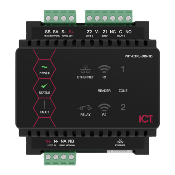
SB SA S- S+ Z2 V- Z1 NC C NO RS485 NETWORK 12VDC OUT INPUT 2 INPUT 1 RELAY 1 N+ N- NA NB 12VDC IN/OUT RS485 NETWORK ETHERNET Power up the controller. Wait for the status indicator to begin flashing steadily. When the controller starts up it will use the following temporary settings: IP address : 192.168.111.222 Subnet Mask : 255.255.255.0... - Page 44 SB SA S- S+ Z2 V- Z1 NC C NO RS485 NETWORK 12VDC OUT INPUT 2 INPUT 1 RELAY 1 N+ N- NA NB 12VDC IN/OUT RS485 NETWORK ETHERNET Power up the controller. Wait for the status indicator to begin flashing steadily. Remove the wire link(s).
-
Page 45: Led Indicators
LED Indicators Protege DIN rail modules feature comprehensive diagnostic indicators that can aid the installer in diagnosing faults and conditions. In some cases an indicator may have multiple meanings depending on the status indicator display at the time. Power Indicator The power indicator is lit when the correct input voltage is applied to the controller. -
Page 46: Battery Indicator
Battery Indicator PoE models only The battery indicator shows the status of the backup battery. State Description Flashing (red) Backup battery is disconnected On (red) Backup battery failed its dynamic battery test On (green) Last backup battery dynamic test successful Ethernet Link Indicator The ethernet indicator shows the status of the ethernet connection. -
Page 47: Input Indicators
Input Indicators Whenever an input on the module is programmed with an input type and area, the input status will be displayed on the front panel indicator corresponding to the physical input number. This allows for easy test verification of inputs without the need to view the inputs from the keypad or the Protege software. -
Page 48: Mechanical Diagram
Mechanical Diagram The mechanical diagram shown below outlines the essential details needed to help ensure the correct installation of the controller. PRT-WX-DIN-1D | Protege WX DIN Rail Single Door Controller | Installation Manual... -
Page 49: Mechanical Layout
Mechanical Layout The mechanical layout shown below outlines the essential details needed to help ensure correct installation and mounting. All measurements are shown in millimeters. 78.40 Front 78.40 39.20 39.20 Back 67.18 PRT-WX-DIN-1D | Protege WX DIN Rail Single Door Controller | Installation Manual... -
Page 50: Technical Specifications
Technical Specifications The following specifications are important and vital to the correct operation of this product. Failure to adhere to the specifications will result in any warranty or guarantee that was provided becoming null and void. Ordering Information Order Code PRT-WX-DIN-1D PRT-WX-DIN-1D-POE Protege WX DIN Rail Single... - Page 51 N+ N- input terminals, and the maximum current is governed by the trip level of these fuses. The ICT implementation of OSDP conforms to a subset of the OSDP functionality. For specifications and reader configuration, refer to AN-254 Configuring OSDP Readers, available from the ICT website.
-
Page 52: New Zealand And Australia
New Zealand and Australia General Product Statement The RCM compliance label indicates that the supplier of the device asserts that it complies with all applicable standards. Intruder Detection Maintenance Routine Integrated Control Technology recommends regular maintenance of the Protege system, including Protege controllers, expander modules and other connected devices. -
Page 53: Recommended Routine Maintenance Procedures
Recommended Routine Maintenance Procedures Preliminary Procedures Task Frequency Description If the system is monitored, the monitoring company must be notified before any testing begins (commonly referred to as placing the Notify the alarm As required system 'on test'). monitoring company prior to start of (place account 'on maintenance... - Page 54 Task Frequency Description Replace each power supply battery as required with another of Once per 3-5 years, Replace equivalent or better specifications. Record the installation date of the or as specified by the battery new battery in the system maintenance records and in a clearly visible battery manufacturer location within the equipment enclosure or on the battery itself.
- Page 55 Task Frequency Description Note: This procedure must be pre-arranged in consultation with the monitoring station. As agreed between Test the operation of each audible and visible warning device. monitoring company and client, but not Consult the maintenance sheets for a list of all outputs to be tested. ⦁...
-
Page 56: European Standards
European Standards CE Statement Conforms where applicable to European Union (EU) Low Voltage Directive (LVD) 2014/35/EU, Electromagnetic Compatibility (EMC) Directive 2014/30/EU, Radio Equipment Directive (RED)2014/53/EU and RoHS Recast (RoHS2) Directive: 2011/65/EU + Amendment Directive (EU) 2015/863. This equipment complies with the rules, of the Official Journal of the European Union, for governing the Self Declaration of the CE Marking for the European Union as specified in the above directive(s). -
Page 57: Uk Pd 6662:2017 And Bs 8243
EN50131 In order to comply with EN 50131-1 the following points should be noted: ⦁ Ensure for Grade 3 or 4 compliant systems, the minimum PIN length is set for 6 digits. ⦁ To comply with EN 50131-1 Engineer access must first be authorized by a user, therefore Installer codes will only be accepted when the system is unset. -
Page 58: Fcc Compliance Statements
FCC Compliance Statements FCC Rules and Regulations CFR 47, Part 15, Subpart A This equipment complies with the limits for a Class A digital device, pursuant to Part 15 of the FCC rules. Operation is subject to the following two conditions: This device may not cause harmful interference. -
Page 59: Industry Canada Statement
Industry Canada Statement ICES-003 This is a Class A digital device that meets all requirements of the Canadian Interference Causing Equipment Regulations. CAN ICES-3 (A)/NMB-3 (A) PRT-WX-DIN-1D | Protege WX DIN Rail Single Door Controller | Installation Manual... -
Page 60: Disclaimer And Warranty
Integrated Control Technology Ltd nor its employees shall be liable under any circumstances to any party in respect of decisions or actions they may make as a result of using this information. In accordance with the ICT policy of enhanced development, design and specifications are subject to change without notice. - Page 61 In accordance with the ICT policy of enhanced development, design and specifications are subject to change without notice.
Need help?
Do you have a question about the Protege PRT-WX-DIN-1D and is the answer not in the manual?
Questions and answers