
Related Manuals for ICT PRT-CTRL-DIN-IP


Summary of Contents for ICT PRT-CTRL-DIN-IP
- Page 1 PRT-CTRL-DIN-IP / PRT-CTRL-DIN Protege GX DIN Rail Integrated System Controller Installation Manual...
- Page 2 The specifications and descriptions of products and services contained in this document were correct at the time of printing. Integrated Control Technology Limited reserves the right to change specifications or withdraw products without notice. No part of this document may be reproduced, photocopied, or transmitted in any form or by any means (electronic or mechanical), for any purpose, without the express written permission of Integrated Control Technology Limited.
-
Page 3: Table Of Contents
Controller Editions Installation Requirements Wiring Grounding Requirements Safety Grounding Earth Ground Connection Mounting Removal Wiring Diagram: PRT-CTRL-DIN Wiring Diagram: PRT-CTRL-DIN-IP Connections Power Requirements Auxiliary Outputs Encrypted Module Network Module Wiring End of Line (EOL) Resistors Telephone Dialer Cellular Modem Ethernet 10/100 Network Interface... - Page 4 Ethernet Link Indicator Modem Indicator Reader Data Indicators Bell Indicator Relay Indicators Input Indicators Mechanical Diagram: PRT-CTRL-DIN Mechanical Diagram: PRT-CTRL-DIN-IP Mechanical Layout Technical Specifications Current and Validation Example New Zealand and Australia Intruder Detection Maintenance Routine Peripheral Devices Testing Frequency...
- Page 5 UL Operation Mode ULC Compliance Requirements CAN/ULC-S304 CAN/ULC-S319 CAN/ULC-S559 UL Compliance Requirements UL1610 UL294 FCC Compliance Statements Industry Canada Statement Disclaimer and Warranty PRT-CTRL-DIN | Protege GX DIN Rail Integrated System Controller | Installation Manual...
-
Page 6: Introduction
Contact ID or SIA protocols. It can also communicate over IP, or via connection to the PRT-4G-USB DIN Rail Cellular Modem. The PRT-CTRL-DIN-IP does not include a built-in modem. It can communicate alarms and upload information ⦁... -
Page 7: Installation Requirements
Installation Requirements This equipment is to be installed in accordance with: The product installation instructions ⦁ UL 681 - Installation and Classification of Burglar and Holdup Systems ⦁ UL 827 - Central-Station Alarm Services ⦁ CAN/ULC-S301, Central and Monitoring Station Burglar Alarm Systems ⦁... -
Page 8: Grounding Requirements
Grounding Requirements An effectively grounded product is one that is intentionally connected to earth ground through a ground connection or connections of sufficiently low impedance and having sufficient current-carrying capacity to prevent elevated voltages which may result in undue hazard to connected equipment or to persons. - Page 9 DIN Rail Ground Connections (multiple cabinets in different rooms, sectors, or buildings) Module Network (RS-485 N+, N-, NA and NB) DIN Rail Enclosure DIN Rail Enclosure DIN Rail Enclosure Controller Reader Expander Input Expander Dialer’s Earth Ground Connection Power Supply Input Expander Input Expander Input Expander...
-
Page 10: Mounting
Mounting Protege DIN rail modules are designed to mount on standard DIN rail either in dedicated DIN cabinets or on generic DIN rail mounting strip. When installing a DIN rail module, ensure that there is adequate clearance around all sides of the device and that air flow to the vents of the unit is not restricted. -
Page 11: Wiring Diagram: Prt-Ctrl-Din
Wiring Diagram: PRT-CTRL-DIN CAUTION: Incorrect wiring may result in damage to the unit. N.C Input Contact N.C Input Contact Door Contact Door Contact N.O Input Contact N.O Input Contact N.C Input Contact N.C Input Contact Bond Sense Bond Sense Shield Shield N.O Input Contact N.O Input Contact... -
Page 12: Wiring Diagram: Prt-Ctrl-Din-Ip
Wiring Diagram: PRT-CTRL-DIN-IP CAUTION: Incorrect wiring may result in damage to the unit. N.C Input Contact N.C Input Contact Door Contact Door Contact N.O Input Contact N.O Input Contact N.C Input Contact N.C Input Contact Bond Sense Bond Sense Shield Shield N.O Input Contact... -
Page 13: Connections
Connections Power Requirements Power is supplied to the controller by a 12V DC power supply connected to the N+ and N- terminals. The controller does not contain internal regulation or isolation and any clean 12V DC supply is suitable for this purpose. Termination of wiring to the module while power is applied or the battery is connected may cause serious damage to the unit and will VOID ALL WARRANTIES OR GUARANTEES. - Page 14 Example 4A Power Supply Connection: In a small installation this same power supply can be used to supply the module network as well, so long as the maximum load of the power supply is not exceeded. In larger installations, the power supply may need to be split to allow for load sharing between several supplies.
-
Page 15: Auxiliary Outputs
Auxiliary Outputs The auxiliary outputs (V- V+) of the controller can be used to supply other equipment. Note that there is no onboard regulation or isolation for these outputs; they are a fused feed-through from the N+ N- input terminals. When using these outputs to supply other devices, be sure not to exceed the rating of the internal fuses as outlined in the Technical... -
Page 16: End Of Line (Eol) Resistors
End of Line (EOL) Resistors The 330 ohm EOL (End of Line) resistor provided in the accessory bag must be inserted between the NA and NB terminals of the first and last modules on the RS-485 network. These are the modules physically located at the ends of the RS-485 network cabling. -
Page 17: Telephone Dialer
Telephone Dialer Modem model only. The controller provides the ability to communicate alarms and upload information to remote systems using the onboard 2400bps modem. The telephone line can be connected directly to the controller using the onboard telephone connection terminals. Telco line tip and ring input Telco line out... -
Page 18: Ethernet 10/100 Network Interface
Ethernet 10/100 Network Interface The communication between the Protege system and the controller uses a 10/100 ethernet network operating the TCP/IP protocol suite. The IP address of the controller can be configured using an LCD keypad terminal or via the built-in web interface. -
Page 19: Door Access Control
⦁ Note: The reader and cable shield wires must be joined at the reader pigtail splice for all MIFARE capable ICT card readers. Older readers which are internally grounded and third-party readers do not require the shield wires to be joined. -
Page 20: Rs-485 Reader Connection (Entry Only)
RS-485 Reader Connection (Entry Only) The following diagram shows the connection of a single RS-485 reader connected in entry only mode. Reader shield is Shield wires SHIELD not terminated connected inside the reader at the splice BLACK GREEN WHITE ORANGE BROWN Shield is frame grounded at... -
Page 21: Wiegand Reader Connection
Wiegand Reader Connection The controller allows the connection of 2 magnetic clock and data reading devices or 4 Wiegand reading devices and the ability to control 2 doors (entry or exit only) or 1 door (entry and exit). The following diagrams show the connection of a standard Wiegand reader with the controller controlling an access door and an entry/exit door. -
Page 22: Magnetic Reader Connection
Magnetic Reader Connection The controller allows the connection of standard magnetic track 2 format cards and provision is made in the software for a large number of formats. Formats include BIN number for ATM access control and first 4, 5 and 6 card numbers. -
Page 23: Lock Output Connection
N.C. Input Contact REN Input Bond Sense N.O. Input Contact N.C. Input Contact REX Input Door Contact N.O. Input Contact Inputs 1-4 and 5-8 can operate as either general purpose inputs or as onboard reader inputs. If used as general purpose inputs, make sure that these inputs are not defined in the onboard reader set up. -
Page 24: Programming The Onboard Reader
To use the lock outputs in conjunction with the onboard reader module, the lock output for the door associated with the reader port must be configured to be the desired lock output on the controller. This is not configured by default. - Page 25 The default settings are shown in the following table: Input Access Control Function Default Setting Input 1 Door Contact, Port 1 Door Contact, Port 1 Input 2 REX Input, Port 1 REX Input, Port 1 Input 3 Bond Sense, Port 1 General Purpose Input Input 4 REN Input, Port 1...
-
Page 26: Inputs
Inputs The controller has 8 onboard inputs for monitoring the state of devices such as magnetic contacts, motion detectors and temperature sensors. Devices connected to the inputs can be installed to a maximum distance of 300m (1000ft) from the module when using 22 AWG wire. Magnetic contacts shall be listed to UL 634 to comply with UL installation standards and ⦁... -
Page 27: Eol Resistor Value Options
No EOL Resistor Input Configuration N.C Input Contact EOL Resistor Value Options When using the EOL resistor configuration, the EOL resistor option must be configured based on the site requirements. Note these resistor options are supported on the controller but not all resistor options are supported on all Protege field modules. -
Page 28: Trouble Inputs
Duplex Input Configuration Input 2 Input 1 N.C Input Contact N.C Input Contact N.C Tamper The following table indicates the position and resistor configuration corresponding to each input address: Input Address Position Resistor Enabling duplex inputs will not change the programming of any existing inputs. These must be reprogrammed or rewired to match the new addressing scheme. - Page 29 Input Number Description Type Group CP001:01 Reserved CP001:02 12V Supply Failure Power Fault General CP001:03 Reserved CP001:04 Real Time Clock Not Set RTC/Clock Loss General CP001:05 Service Report Test CP001:06 Service Report Failure to Communicate Reporting Failure General CP001:07 Phone Line Fault (modem model only) Phone Line Lost General CP001:08...
- Page 30 CP001:33 Controller Group Link Lost is not evaluated by UL, cUL, ULC. PRT-CTRL-DIN | Protege GX DIN Rail Integrated System Controller | Installation Manual...
-
Page 31: Outputs
Outputs The controller has 7 onboard outputs. These outputs are used to activate bell sirens, lighting circuits, door locks, relay accessory products and other automation points. The first output on the controller has a special hardware design that allows it to monitor for fault conditions and is ideally suited to driving sirens or warning devices. Bell/Siren Output Not investigated by UL/ULC for local burglary applications. -
Page 32: Relay Outputs
Relay Outputs The relay outputs (CP001:03 and CP001:04) on the controller are Form C relays with normally open and normally closed contacts. These outputs can be used to activate larger relays, sounders and lights, etc. 1K5 OHM Warning: The relay outputs can switch to a maximum capacity of 7A. Exceeding this amount will damage the output. -
Page 33: Hardware Configuration
For information on using the controller's web interface to configure IP network and security settings, see the Protege GX Integrated System Controller Configuration Guide, available from the ICT website. Setting the IP Address from a Keypad If the current IP address of the controller is not known it can be viewed and changed using a Protege keypad. -
Page 34: Temporarily Defaulting The Ip Address
Temporarily Defaulting the IP Address If the currently configured IP address is unknown it can be temporarily set to 192.168.111.222 so that you can connect to the web interface to view and/or change it. This defaults the IP address for as long as power is applied, but does save the change permanently. -
Page 35: Defaulting A Controller
Defaulting a Controller The controller can be factory defaulted, which resets all internal data and event information. This allows you to remove all programming and start afresh. Defaulting the controller resets the IP address to the factory default IP of 192.168.1.2 Remove power to the controller by disconnecting the 12V DC input. - Page 36 Reinstall previously installed custom HTTPS certificates. Restore any other system settings as required by your site configuration. PRT-CTRL-DIN | Protege GX DIN Rail Integrated System Controller | Installation Manual...
-
Page 37: Led Indicators
LED Indicators Protege DIN rail modules feature comprehensive diagnostic indicators that can aid the installer in diagnosing faults and conditions. In some cases an indicator may have multiple meanings depending on the status indicator display at the time. Power Indicator The power indicator is lit when the correct input voltage is applied to the controller. -
Page 38: Modem Indicator
Modem Indicator Modem model only. The Modem indicator shows the status of the onboard modem. State Description On (green) Modem has control of telephone line Modem is not active Reader Data Indicators The R1 and R2 indicators display the status of the data being received by the onboard readers. State Description Short flash... -
Page 39: Input Indicators
Input Indicators Whenever an input on the module is programmed with an input type and area, the input status will be displayed on the front panel indicator corresponding to the physical input number. This allows for easy test verification of inputs without the need to view the inputs from the keypad or the Protege software. -
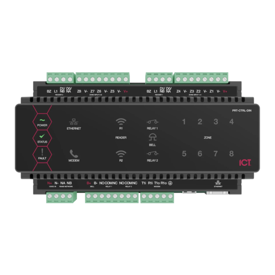
Page 40: Mechanical Diagram: Prt-Ctrl-Din
Mechanical Diagram: PRT-CTRL-DIN The mechanical diagram shown below outlines the essential details needed to help ensure the correct installation of the controller. Inputs 5 to 8 Reader Port Reader Port Inputs 1 to 4 D1/ D0/ D1/ D0/ BZ L1 NB NA V- Z7 Z6 V- Z5 V- V+ BZ L1 NB NA Z4 V- Z3 Z2 V- Z1 V- V+... -
Page 41: Mechanical Diagram: Prt-Ctrl-Din-Ip
Mechanical Diagram: PRT-CTRL-DIN-IP The mechanical diagram shown below outlines the essential details needed to help ensure the correct installation of the controller. Inputs 5 to 8 Reader Port Reader Port Inputs 1 to 4 D1/ D0/ D1/ D0/ BZ L1 NB NA... -
Page 42: Mechanical Layout
Mechanical Layout The mechanical layout below outlines the essential details needed to help ensure correct installation and mounting. All measurements are shown in millimeters. 156.80 Front 156.80 42.40 72.00 42.40 Back 139.18 PRT-CTRL-DIN | Protege GX DIN Rail Integrated System Controller | Installation Manual... -
Page 43: Technical Specifications
The following specifications are important and vital to the correct operation of this product. Failure to adhere to the specifications will result in any warranty or guarantee that was provided becoming null and void. Ordering Information Order Code PRT-CTRL-DIN PRT-CTRL-DIN-IP Protege GX DIN Rail Integrated System Protege GX DIN Rail Integrated System Product Name Controller... - Page 44 If combining reader technologies, they must be connected on separate ports. The ICT implementation of OSDP conforms to a subset of the OSDP functionality. For specifications and reader configuration, refer to Application Note 254: Configuring OSDP Readers, available from the ICT website.
-
Page 45: Current And Validation Example
Current and Validation Example The example shown below refers to the specifications needed to help ensure the correct installation of a Protege controller. Specifications should be validated to ensure that individual maximum currents and total combined current are not exceeded. Example External Devices Connected to Panel 4 EDGE PIR Motion Detectors (Inputs 1-4) connected on AUX1 Output... -
Page 46: New Zealand And Australia
New Zealand and Australia General Product Statement The RCM compliance label indicates that the supplier of the device asserts that it complies with all applicable standards. Intruder Detection Maintenance Routine Integrated Control Technology recommends regular maintenance of the Protege system, including Protege controllers, expander modules and other connected devices. -
Page 47: Recommended Routine Maintenance Procedures
Recommended Routine Maintenance Procedures Preliminary Procedures Task Frequency Description If the system is monitored, the monitoring company must be notified before any testing begins (commonly referred to as placing the Notify the alarm As required system 'on test'). monitoring company prior to start of (place account 'on maintenance... - Page 48 Task Frequency Description Replace each power supply battery as required with another of Once per 3-5 years, Replace equivalent or better specifications. Record the installation date of the or as specified by the battery new battery in the system maintenance records and in a clearly visible battery manufacturer location within the equipment enclosure or on the battery itself.
- Page 49 Task Frequency Description Note: This procedure must be pre-arranged in consultation with the monitoring station. As agreed between Test the operation of each audible and visible warning device. monitoring company and client, but not Consult the maintenance sheets for a list of all outputs to be tested. ⦁...
-
Page 50: European Standards
European Standards CE Statement Conforms where applicable to European Union (EU) Low Voltage Directive (LVD) 2014/35/EU, Electromagnetic Compatibility (EMC) Directive 2014/30/EU, Radio Equipment Directive (RED)2014/53/EU and RoHS Recast (RoHS2) Directive: 2011/65/EU + Amendment Directive (EU) 2015/863. This equipment complies with the rules, of the Official Journal of the European Union, for governing the Self Declaration of the CE Marking for the European Union as specified in the above directive(s). - Page 51 EN50131 In order to comply with EN 50131-1 the following points should be noted: ⦁ Ensure for Grade 3 or 4 compliant systems, the minimum PIN length is set for 6 digits. ⦁ To comply with EN 50131-1 Engineer access must first be authorized by a user, therefore Installer codes will only be accepted when the system is unset.
-
Page 52: Uk Conformity Assessment Mark
UK Conformity Assessment Mark General Product Statement The UKCA Compliance Label indicates that the supplier of the device asserts that it complies with all applicable standards. UK PD 6662:2017 and BS 8243 Protege systems conform to PD 6662:2017 and BS 8243 at the security grade and notification option applicable to the system. -
Page 53: Ul And Ulc Installation Requirements
UL and ULC Installation Requirements Only UL / ULC listed compatible products are intended to be connected to a UL / ULC listed control system. For UL 1610, ULC S304 and ULC S559 installations where a secondary method of reporting is required, use the onboard 2400bps modem included with the modem controller model, or incorporate the PRT-4G-USB cellular modem module into the installation with the non-modem controller model. -
Page 54: Ul Operation Mode
UL Operation Mode UL operation mode should be enabled in Protege GX system settings. Select Sites | Controllers | Options and then select Advance UL Operation for the Protege GX system to operate in UL compliance mode. This setting has the following effects: ⦁... - Page 55 The common equipment of each signal receiving center control unit shall be limited to 1000 alarm systems. Number of attempts ⦁ In the event of unsuccessful communication, a digital alarm communicator transmitter shall make a minimum of 5 and a maximum of 10 attempts. Where the maximum number of attempts to complete the sequence is reached, an indication of the failure shall be made at the premises.
- Page 56 The Ethernet Link Failure trouble input must be programmed. The Trouble Input Area must be armed. Refer to the section Trouble Inputs | Areas and Input Types in the Operator Reference Manual. The Log Modem Events to Event Buffer option must be selected in the backup reporting service. Network and Domain Access ⦁...
-
Page 57: Can/Ulc-S319
Compromise Attempt Events ⦁ ArmorIP detects the reception of any invalid packet on the programmed port as a potential system compromise attempt. Each compromise attempt sends a notification to the receiver, and logs a Compromise Attempt event under the Live Panel Events. The event is sent with the following details: Account Code as defined in the Serial Receiver settings Event Code 0x163... - Page 58 The Trouble Area must be armed. Refer to the section Trouble Inputs | Areas and Input Types in the Operator Reference Manual. In the ArmorIP Internet Monitoring Software the Poll Time must be set to 40 seconds and the Grace Time must be set to 20 seconds.
- Page 59 CAN/ULC-S559 CONTROLLER ACTIVE COMMUNICATION Metal Conduit Note: All cables shall be protected within metal conduits. ENCLOSURE 24h Standby / Backup ULC certified 12V DC Power Supply CONTROLLER Required for T elecom Equipment 12V DC MAINS SUPPLY (120V AC) TELECOM ETHERNET EQUIPMENT INTERNET BATT...
- Page 60 CAN/ULC-S559 CONTROLLER PASSIVE COMMUNICATION: MODEM DIALER Metal Conduit Note: All cables shall be protected within metal conduits.a ENCLOSURE 24h Standby / Backup ULC certified 12V DC Power Supply CONTROLLER Required for T elecom Equipment 12V DC MAINS SUPPLY (120V AC) TELECOM ETHERNET EQUIPMENT...
- Page 61 CAN/ULC-S559 CONTROLLER ACTIVE COMMUNICATION: CELLULAR MODEM Metal Conduit Note: All cables shall be protected within metal conduits. ENCLOSURE 24h Standby / Backup ULC certified 12V DC Power Supply CONTROLLER Required for T elecom Equipment 12V DC MAINS SUPPLY (120V AC) TELECOM ETHERNET EQUIPMENT...
-
Page 62: Ul Compliance Requirements
Fire area inputs must be programmed as follows: FACP Fire Alarm Signal input type must be programmed as Fire. Supervisory Trouble Signal input type must be programmed as 24 HR Silent. Trouble Signal input type must be programmed as 24 HR Silent. Please refer to the section Inputs | Areas and Input Types in the Operator Reference Manual. - Page 63 means, at least one of the signal transmission channels shall send a signal to the central-station to report the fault within 200 seconds. The Report IP and Contact ID services must be programmed and enabled within the Protege system. The Protege controller is compatible with the ArmorIP Internet Monitoring Receiver. Poll Time must be set to 40 seconds and the Grace Time must be set to 20 seconds.
-
Page 64: Ul294
UL294 ⦁ The Protege controller and reader expander module are intended to be mounted within the enclosure (refer to UL/ULC Installation Cabinet Options), installed inside the protected premise, and are UL 294 Listed for Attack Class I applications only. Exit devices and wiring must be installed within the protected area. ⦁... -
Page 65: Fcc Compliance Statements
FCC Compliance Statements FCC PART 15, WARNINGS: INFORMATION TO USER This equipment complies with the limits for a Class A digital device, pursuant to Part 15 of the FCC Rules. These limits are designed to provide reasonable protection against harmful interference in a residential installation. This equipment generates, uses and can radiate radio frequency energy and, if not installed and used in accordance with the instructions, may cause harmful interference to radio communications. - Page 66 The REN is used to determine the number of devices that may be connected to a telephone line. Excessive RENs on a telephone line may result in the devices not ringing in response to an incoming call. In most but not all areas, the sum of RENs should not exceed five (5.0).
- Page 67 Customer Premises Equipment and Wiring Network Service Provider's Computer RJ-31X Facilities Jack Unused Alarm Dialing RJ-11 Jack Equipment Telephone Line Telephone Network Unused Demarcation Fax Machine RJ-11 Jack Telephone Point Answering System Telephone Alarm dialing equipment applies to the modem model only. PRT-CTRL-DIN | Protege GX DIN Rail Integrated System Controller | Installation Manual...
-
Page 68: Industry Canada Statement
Industry Canada Statement This class A digital apparatus complies with Canadian ICES-003. Cet appareil numérique de la classe A est conforme à la norme NMB-003 du Canada. CAN ICES-3 (A)/NMB-3(A) Modem model only. Modèle de modem uniquement. This product meets the applicable Industry Canada technical specifications. The Ringer Equivalence Number (REN) for this terminal equipment is 0.0. -
Page 69: Disclaimer And Warranty
Integrated Control Technology Ltd nor its employees shall be liable under any circumstances to any party in respect of decisions or actions they may make as a result of using this information. In accordance with the ICT policy of enhanced development, design and specifications are subject to change without notice. - Page 70 In accordance with the ICT policy of enhanced development, design and specifications are subject to change without notice.
Need help?
Do you have a question about the PRT-CTRL-DIN-IP and is the answer not in the manual?
Questions and answers