Table of Contents
Advertisement
Quick Links
Advertisement
Table of Contents

Related Manuals for ICT Protege GX PRT-CTRL-DIN-1D


Summary of Contents for ICT Protege GX PRT-CTRL-DIN-1D
- Page 1 PRT-CTRL-DIN-1D Protege GX DIN Rail Single Door Controller Installation Manual...
- Page 2 The specifications and descriptions of products and services contained in this document were correct at the time of printing. Integrated Control Technology Limited reserves the right to change specifications or withdraw products without notice. No part of this document may be reproduced, photocopied, or transmitted in any form or by any means (electronic or mechanical), for any purpose, without the express written permission of Integrated Control Technology Limited.
-
Page 3: Table Of Contents
Contents Introduction Single Door Controller Editions Installation Requirements Grounding Requirements Safety Grounding Earth Ground Connection Mounting Removal Connections Power Requirements Auxiliary Outputs Power over Ethernet (PoE) Encrypted Module Network Module Wiring End of Line (EOL) Resistors Backup Battery Ethernet 10/100 Network Interface Configuration Configuring a Controller via the Web Interface Home Page... - Page 4 Configuring a Controller Addressing Modules Door Access Control RS-485 Reader Locations RS-485 Reader Connection (Entry Only) RS-485 Reader Connection (Entry/Exit) Door Contact Connection Lock Output Connection Programming the Onboard Reader Inputs EOL Resistor Value Options Trouble Inputs Outputs Hardware Configuration Temporarily Defaulting the IP Address Defaulting a Controller LED Indicators...
- Page 5 Peripheral Devices Testing Frequency Recommended Routine Maintenance Procedures European Standards FCC Compliance Statements Industry Canada Statement Disclaimer and Warranty PRT-CTRL-DIN-1D | Protege GX DIN Rail Single Door Controller | Installation Manual...
-
Page 6: Introduction
Introduction The Protege GX DIN Rail Single Door Controller is the central processing unit responsible for the control of security, access control and building automation in the Protege GX system. It communicates with all system modules, stores all configuration and transaction information, processes all system communication, and reports alarms and system activity to a monitoring station or remote computer. -
Page 7: Installation Requirements
Installation Requirements This equipment is to be installed in accordance with: The product installation instructions ⦁ AS/NZS 2201.1 Intruder alarm systems ⦁ The Local Authority Having Jurisdiction (AHJ) ⦁ PRT-CTRL-DIN-1D | Protege GX DIN Rail Single Door Controller | Installation Manual... -
Page 8: Grounding Requirements
Grounding Requirements An effectively grounded product is one that is intentionally connected to earth ground through a ground connection or connections of sufficiently low impedance and having sufficient current-carrying capacity to prevent elevated voltages which may result in undue hazard to connected equipment or to persons. - Page 9 DIN Rail Ground Connections (multiple cabinets in different rooms, sectors, or buildings) Module Network (RS-485 N+, N-, NA and NB) DIN Rail Enclosure DIN Rail Enclosure DIN Rail Enclosure Controller Reader Expander Input Expander Dialer’s Earth Ground Connection Power Supply Input Expander Input Expander Input Expander...
-
Page 10: Mounting
Mounting Protege DIN Rail modules are designed to mount on standard DIN Rail either in dedicated DIN cabinets or on generic DIN Rail mounting strip. When installing a DIN Rail module, ensure that there is adequate clearance around all sides of the device and that air flow to the vents of the unit is not restricted. -
Page 11: Connections
Connections Power Requirements Power is supplied to the Controller by a 12V DC power supply connected to the N+ and N- terminals. The Controller does not contain internal regulation or isolation and any clean 12V DC supply is suitable for this purpose. - Page 12 Example 4A Power Supply Connection: In a small installation this same power supply can be used to supply the module network as well, so long as the maximum load of the power supply is not exceeded. In larger installations, the power supply may need to be split to allow for load sharing between several supplies.
-
Page 13: Auxiliary Outputs
Auxiliary Outputs The auxiliary outputs (S- S+) of the Controller can be used to supply other equipment. Note that there is no onboard regulation or isolation for these outputs - they are a fused feed-through from the N+ N- input terminals. -
Page 14: Encrypted Module Network
Encrypted Module Network The Controller incorporates encrypted RS-485 communications technology. Connection of the communications should be performed according to the following diagram. Controller Network Module Network Module Shielded Cable Shielded Cable Shield is frame Shields are Shield not grounded at connected together connected one point... -
Page 15: End Of Line (Eol) Resistors
End of Line (EOL) Resistors The 330 Ohm EOL (End of Line) resistor provided in the accessory bag MUST be inserted between the NA and NB terminals of the FIRST and LAST modules on the RS-485 network. These are the modules physically located at the ends of the RS-485 network cabling. -
Page 16: Ethernet 10/100 Network Interface
In addition to the dynamic battery test procedure, the Power Supply performs a battery presence test every 60 seconds, which determines whether the presence of a backup battery is detected. Similarly, a battery condition alarm will be generated and the battery trouble input associated with the address assigned to the Controller will also be activated. -
Page 17: Configuration
Configuration Configuring a Controller via the Web Interface The controller's built-in web interface allows you to configure specific settings in order to get the controller online with a Protege GX server. These settings include: ⦁ IP addressing – IP address, Subnet mask, Gateway and DNS settings ⦁... - Page 18 HTTP Port*: The default port is 80. This can be changed to any network port that is not occupied. ⦁ Use DHCP: When enabled the Controller will use DHCP to dynamically allocate an IP address instead of ⦁ using a static IP address. To use this there must be a DHCP server on the network you are attempting to connect to.
-
Page 19: Operators
BIN File: This section is used to update the firmware of the controller. Click Choose File to browse to the firmware file (.bin format) supplied by ICT, then click Upload to install the new firmware on the controller. This process will take approximately 10 minutes and the controller will not be able to perform its normal functions during this period. -
Page 20: Setting The Ip Address
As a guideline, a secure password should have these features: ⦁ Minimum 8 characters in length ⦁ Combination of upper and lower case letters ⦁ Combination of numbers and letters ⦁ Inclusion of special characters Setting the IP Address There are two methods for setting the IP address of a controller. The recommended method is using the built-in web interface: With the controller connected to your network, type the current IP address into the address bar of your web browser. -
Page 21: Adding A Controller With Default Records
Add an individual controller record: To add just the Controller. Any expander modules, doors, groups and other programming must be added manually. Add new controller based on an existing controller: To duplicate the programming of a previously configured Controller. Once added, the Controller will require configuration to define settings including the serial number and communication parameters. -
Page 22: Adding A Controller Based On An Existing Controller
Assign to Reader Expanders: Assigns the first door to the Reader One programming of the first Reader ⦁ Expander, the second door to the Reader Two programming of the first Reader Expander, the third door to the Reader One programming of the second Reader Expander, etc. Assign Reader Lock Output to Door Configuration: Assigns the Lock Output programming of the first door ⦁... - Page 23 Download Server: Defines the download server used by the controller. ⦁ Control and Status Request Port: The IP port through which control commands will be sent. By default this ⦁ is port 21001. Last Known IP Address: Shows the last IP address that the controller communicated to the server on. (Read ⦁...
- Page 24 controller and the Protege GX database. Disable Controller Encryption: Instructs the software to stop using encryption. To avoid encryption being ⦁ disabled accidentally or maliciously, this option will NOT change the encryption setting in the controller itself. To stop the controller from using encryption it must be hardware defaulted. Encryption Enabled: Read only field that indicates if encryption is enabled.
-
Page 25: Addressing Modules
Bit Options (1-4) ⦁ Set Bit: A set bit defines a location in the received data that must always be set (or a logical '1'). The set bit defines the location of the bit in the received data. ⦁ Clear Bit: A clear bit defines a location in the received data that must always be cleared (or a logical '0'). The clear bit defines the location of the bit in the received data. -
Page 26: Door Access Control
The shield connection must only be connected at one end of the cable in the metallic enclosure (frame ⦁ grounded). All ICT readers are shipped with single LED mode set as default and are fully compatible with the Protege system, such as tSec Standard Readers, tSec Mini Readers, etc. RS-485 Reader Locations... -
Page 27: Rs-485 Reader Connection (Entry/Exit)
RS-485 Reader Connection (Entry/Exit) The following diagram shows the connection of two RS-485 readers connected to provide an entry/exit configuration. SHIELD BLACK Shielded Cable GREEN WHITE ORANGE BROWN Shield is frame grounded at BLUE one point YELLOW VIOLET ENTRY SHIELD BLACK Shielded Cable GREEN... -
Page 28: Door Contact Connection
Door Contact Connection The Controller allows the connection of 2 contacts for monitoring and controlling the door. Typical Configuration of Door Monitoring Contacts: Each of these inputs can be used for either the door function that is automatically assigned or as a general purpose input. -
Page 29: Programming The Onboard Reader
REX Input, Port 1 The controller's onboard reader port supports an RS-485 reader interface allowing ICT 485 readers to be configured. The option is available to select the onboard reader's port type to ICT 485 from the Reader Expander menu. -
Page 30: Inputs
Inputs The Controller has 2 onboard inputs for monitoring the state of devices such as magnetic contacts, motion detectors and temperature sensors. Devices connected to the inputs can be installed to a maximum distance of 300m (1000ft) from the module when using 22 AWG wire. Inputs can be programmed. -
Page 31: Trouble Inputs
Value 1 Value 2 Monitored Status No Resistor No Resistor Open, Closed Open, Closed, Tamper, Short Open, Closed, Tamper, Short Open, Closed, Tamper, Short Open, Closed, Tamper, Short Open, Closed, Tamper, Short Open, Closed, Tamper, Short Trouble Inputs Trouble inputs are used to monitor the status of the Controller and in most cases are not physically connected to an external input. -
Page 32: Outputs
Outputs The Controller has one onboard output (CP001:03) which is a Form C relay having normally open and normally closed contacts. This output can be used to activate larger relays, sounders, lights, locks etc. Example Relay Connection: Warning: The Relay outputs can switch to a maximum capacity of 7A. Exceeding this amount will damage the output. -
Page 33: Hardware Configuration
Hardware Configuration Temporarily Defaulting the IP Address If the currently configured IP address is unknown, it can be temporarily set to 192.168.111.222 so that you can connect to the web interface to view and/or change it. This resets the IP address for as long as power is applied, but does save the change permanently. -
Page 34: Defaulting A Controller
Gateway : 192.168.111.254 DHCP : disabled Connect to the Controller by entering 192.168.111.222 into the address bar of your web browser, and view or change the IP address as required. Remember to change the subnet of your PC or laptop to match the subnet of the Controller. Remove the wire link(s) and power cycle to the Controller again. - Page 35 Power up the Controller. Remove the wire link(s). The system will now be defaulted with all programming and settings returned to factory configuration. Defaulting the Controller does not reset the IP address. Refer to Configuring the IP Address for instructions on how to reset the address.
-
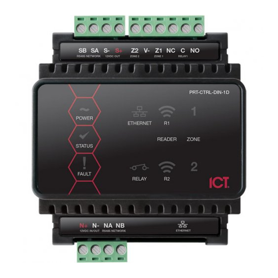
Page 36: Led Indicators
LED Indicators Protege DIN Rail modules feature comprehensive diagnostic indicators that can aid the installer in diagnosing faults and conditions. In some cases an indicator may have multiple meanings depending on the status indicator display at the time. Power Indicator The Power indicator is lit when the correct input voltage is applied to the Controller. -
Page 37: Battery Indicator
Battery Indicator PoE models only The Battery indicator shows the status of the backup battery. State Description (with mains power connected - power indicator on) Flashing (red) Backup battery is disconnected On (red) Backup battery failed its dynamic battery test On (green) Last backup battery dynamic test successful State... -
Page 38: Input Indicators
Input Indicators Whenever an input on the module is programmed with an input type and area, the input status will be displayed on the front panel indicator corresponding to the physical input number. This allows for easy test verification of inputs without the need to view the inputs from the keypad or the Protege software. State Description Constantly off... -
Page 39: Mechanical Diagram
Mechanical Diagram The mechanical diagram shown below outlines the essential details needed to help ensure the correct installation of the Controller. PRT-CTRL-DIN-1D | Protege GX DIN Rail Single Door Controller | Installation Manual... -
Page 40: Mechanical Layout
Mechanical Layout The mechanical layout shown below outlines the essential details needed to help ensure the correct installation of the Controller. PRT-CTRL-DIN-1D | Protege GX DIN Rail Single Door Controller | Installation Manual... -
Page 41: Technical Specifications
Technical Specifications The following specifications are important and vital to the correct operation of this product. Failure to adhere to the specifications will result in any warranty or guarantee that was provided becoming null and void. Ordering Information Order Code PRT-CTRL-DIN-1D PRT-CTRL-DIN-1D-POE Protege GX DIN Rail Single... - Page 42 N+ N- input terminals, and the maximum current is governed by the trip level of these fuses. The ICT implementation of OSDP conforms to a subset of the OSDP functionality. For specifications and reader configuration, refer to...
-
Page 43: New Zealand And Australia
New Zealand and Australia General Product Statement The RCM compliance label indicates that the supplier of the device asserts that it complies with all applicable standards. Intruder Detection Maintenance Routine Integrated Control Technology recommends regular maintenance of the Protege system, including Protege controllers, expander modules and other connected devices. -
Page 44: Recommended Routine Maintenance Procedures
Recommended Routine Maintenance Procedures Preliminary Procedures Task Frequency Description If the system is monitored, the monitoring company must be notified before any testing begins (commonly referred to as placing the Notify the alarm As required system 'on test'). monitoring company prior to start of (place account 'on maintenance... - Page 45 Task Frequency Description Test the DC voltage across the B+ and B- terminals of all power supplies. Test battery The recommended voltage range is 13.4 - 13.8 VDC. charge Once per year Note: When the mains power is restored following an AC fail voltage condition, the battery charge voltage may fluctuate between 10.0 - 13.8 VDC while the battery is recharging.
- Page 46 Task Frequency Description Note: This procedure must be pre-arranged in consultation with the monitoring station. ⦁ Consult the maintenance sheets for a list of all inputs to be tested. ⦁ Activate each input by causing it to switch from the closed state to open (alarm) and back to closed.
- Page 47 Follow-up Procedures Task Frequency Description Perform necessary Complete any modifications to the system resulting from the system As required maintenance procedures. Record these in the maintenance sheets modifications and report. At the conclusion of Obtain client sign Obtain the signature of the client or the client's representative on each maintenance the maintenance record.
-
Page 48: European Standards
European Standards CE Statement Conforms where applicable to European Union (EU) Low Voltage Directive (LVD) 2014/35/EU, Electromagnetic Compatibility (EMC) Directive 2014/30/EU, Radio Equipment Directive (RED)2014/53/EU and RoHS Recast (RoHS2) Directive: 2011/65/EU + Amendment Directive (EU) 2015/863. This equipment complies with the rules, of the Official Journal of the European Union, for governing the Self Declaration of the CE Marking for the European Union as specified in the above directive(s). - Page 49 Ensure for Grade 3 or 4 compliant systems, the minimum PIN length is set for 6 digits. ⦁ To comply with EN 50131-1 Engineer access must first be authorized by a user, therefore Installer codes will ⦁ only be accepted when the system is unset. If additional restriction is required then Engineer access may be time limited to the first 30 seconds after the system is unset.
-
Page 50: Fcc Compliance Statements
FCC Compliance Statements FCC Rules and Regulations CFR 47, Part 15, Class A This equipment complies with the limits for a Class A digital device, pursuant to Part 15 of the FCC rules. Operation is subject to the following two conditions: This device may not cause harmful interference. -
Page 51: Industry Canada Statement
Industry Canada Statement ICES-003 This is a Class A digital device that meets all requirements of the Canadian Interference Causing Equipment Regulations. CAN ICES-3 (A)/NMB-3 (A) PRT-CTRL-DIN-1D | Protege GX DIN Rail Single Door Controller | Installation Manual... -
Page 52: Disclaimer And Warranty
Integrated Control Technology Ltd nor its employees shall be liable under any circumstances to any party in respect of decisions or actions they may make as a result of using this information. In accordance with the ICT policy of enhanced development, design and specifications are subject to change without notice. - Page 53 Disclaimer: Whilst every effort has been made to ensure accuracy in the representation of this product, neither Integrated Control Technology Ltd nor its employees shall be liable under any circumstances to any party in respect of decisions or actions they may make as a result of using this information. In accordance with the ICT policy of enhanced development, design and specifications are subject to change without notice.
Need help?
Do you have a question about the Protege GX PRT-CTRL-DIN-1D and is the answer not in the manual?
Questions and answers