
Subscribe to Our Youtube Channel
Related Manuals for ICT Distribution 3 Series


Summary of Contents for ICT Distribution 3 Series
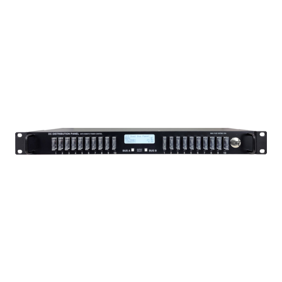
- Page 1 Innovative Circuit Technology Ltd. Distribution Series 3 Dual Bus DC Load Distribution Panels INSTRUCTION MANUAL 855-351-000 Model ICT200DF-20BRC 10/10 Intelligent GMT Fuse Panel Innovative Circuit Technology Ltd.
- Page 2 Carefully observe wiring polarity when making input and output connections • Securely tighten all connections • Do not attempt to service any internal parts. Refer all product service to ICT or an authorized ICT Service Provider CAUTION Risk of personal injury or damage to equipment! Always observe the following: •...
-
Page 3: Table Of Contents
Contents PRODUCT DESCRIPTION ................4 INSTALLATION ..................... 4 OPERATION ....................7 LCD Display ..................8 Status Indicators and Alarms ............11 TCP/IP WEB BASED UTILITY ..............11 Status and Control ................. 13 Device Setup .................. 14 Bus Setup ..................16 Output Setup ................. -
Page 4: Product Description
PRODUCT DESCRIPTION The ICT Dual Bus Distribution Panel provides two 100 amperes (peak) bus inputs with 10 independently controlled and monitored output channels per bus in a compact 1U high chassis for 19 inch rack mounting. All channels are individually protected by GMT type fuses that are rated up to 20 amperes each. - Page 5 • Two clear snap on covers in insulate main dc power connections (shipped on unit) • Two seven-pin alarm output, remote sensor input connector plugs (shipped on unit) • This instruction Manual To complete the installation, install GMT fuses appropriately sized for the connected load devices.
- Page 6 WARNING Risk of serious personal injury or damage to equipment and property! Always observe the following: • Shut off or disconnect all dc power sources before connecting or disconnecting wiring • Use wire and connectors rated for the maximum load current and size of fuse, and keep cable lengths as short as practical •...
-
Page 7: Operation
seven-pin connector plug (lower), and installing in the rear panel. Each Bus Alarm output will trigger for any fuse open, or other alarm related to any channel on that bus (Factory Default). Most alarm conditions can be masked off so that they will not trigger the Alarm output if required, using the web-based graphical interface. -
Page 8: Lcd Display
Energise each bus by closing the main external breaker or disconnect device on the bus input lines. Check that the Distribution Panel LCD display powers up, the internal channel relays close after a short delay, and the connected loads are energised. - Page 9 Main Screen Line 1: The name of the panel (user configurable via the web based graphic interface, default is “ICT Dual Bus Panel”) Line 2: Displays the bus being monitored, Bus A or Bus B Line 3: The system voltage (voltage will blink if the voltage exceeds the Under-...
- Page 10 Figure 4: LCD Display Screens Innovative Circuit Technology Ltd.
-
Page 11: Status Indicators And Alarms
Status Indicators and Alarms The Bus Alarm LEDs on the front panel and the Form-C Bus Alarm contacts on the back are used to indicate an alarm condition. Alarm Trigger Condition Channel Bus Alarm Output Alarm Contact Fuse Off Fuse is open Bus Under-voltage Bus voltage drops change... - Page 12 Launch a web browser. Enter the IP address of the panel in the address field of the browser as shown. If the panel is connected to a network with a DHCP server, the panel will be assigned an IP address automatically. To find the current address of the panel check the Network screen, line three, on the unit’s front panel LCD display.
-
Page 13: Status And Control
Click on any one of the blue buttons in the menu bar on the left side of the screen to select the desired page. To log out, click on the Logout link on the top right of the browser window. The system will also automatically log off the user after 20 minutes of inactivity. -
Page 14: Device Setup
Device Info Site Name: Enter a custom descriptive name for the panel Model: Displays the ICT model number for the panel Hardware: Displays the hardware version of the panel Date and Time Settings Current System Time: Displays the date and time used in the panel’s internal... - Page 15 Note the Sequence Delay time will also be used as the Power Cycling time delay for each output that has the Power Cycling feature enabled on the Output Setup page. Reverse Sequence Order: Checking this box will cause the power on sequence to run in reverse order with output channel 10 on first, ending with output 1, when the Enable Bus button is clicked on the Status and Control page.
-
Page 16: Bus Setup
Data Logging: Data Logging rate: Enable this feature to keep a running record the bus voltage, bus current, channel output currents, fuse status, and alarm inputs at a rate of up to one sample per minute. View this Comma Separated Values (CSV) format log by clicking the Download Log button, and open in any Spreadsheet software, such as Microsoft Excel. -
Page 17: Output Setup
Over-Current Threshold: Enter the maximum total current level for the bus. Current exceeding this level will trigger the Over-Current alarm. Activate Form-C Contact: Checking this box will cause the Alarm relay to trigger for an over-current condition. (default) Send E-mail: Checking this box will cause the unit to send a Bus Over-Current alarm e-mail to the assigned address entered on the E-mail Setup page Output Setup Use this page to configure the settings for each output channel on Bus A and Bus B. - Page 18 Output Load Shedding: Enable Load Shedding: Check this box to disable this output when the bus voltage drops below the load-shedding threshold for at least 30 seconds. This feature can be used to disconnect less critical loads to preserve back-up battery power as the battery voltage drops.
-
Page 19: Network Setup
Network setup Use this page to configure the network settings for the panel. Click on the Save Settings button at the bottom of the page to save any changes and re-boot the panel. NOTE: Saving any changes to the network settings will cause the panel to re-boot, cycling power to all outputs. - Page 20 number must be appended to the URL used to access the panel. (e.g. use URL http://192.168.0.180:8000 for IP address 192.168.0.180, port 8000) HTTPS Port: The HTTPS (HTTP Secure) protocol uses encrypted data transfer between web browsers and servers for higher security. The default HTTPS port is 443.
- Page 21 • Full Device Control: Allow SNMP clients to set all device settings through SNMP. MIB files for full SNMP device control can be downloaded from the ICT Website: https://www.ict-power.com/tools-utilities/ SNMP Contact Information: Assign contact information, such as an operator name and phone number for the panel, which can be read via SNMP queries.
-
Page 22: E-Mail Setup
E-mail Setup Configure these settings to enable automatic e-mail notifications directly from the panel. The information required for this is available from a Network Administrator, or Internet Service Provider. (ISP) E-mail: SMTP Server: Enter the name or the IP address of the SMTP server used for sending outgoing e-mail. -
Page 23: Alarm Setup
The Distribution Panel restarts: Check this box to receive an e-mail notification when the panel restarts after a power failure or a soft reset. Load-Shedding is activated: Check this box to receive an e-mail notification when any of the outputs are disabled or enabled due the voltage crossing one of the load-shed settings configured on the Output Setup page. -
Page 24: User Setup
the e-mail settings must be fully configured on the E-mail Setup page for this to occur. User Setup Use this page to configure passwords for up to 10 users, with the ability to limit who has access to the panel settings. Click on the Save Settings button at the bottom of the page to save any password changes. -
Page 25: Mobile Web App
setting for each output on the Output Setup page. All other setting are maintained during the reset. Restore Factory Default Settings: Clicking the Restore button will restore ALL settings to the original factory default values, including the user passwords. To only restore the network settings and passwords see the Password Reset section. -
Page 26: Password Reset
Mobile Web App The Mobile Web App (shown above) provides information on bus voltage, bus current, input alarm status, and the status and current level of each of the bus output channels. Tapping on an output cell will enable or disable that output. (if logged in using an Administrator or Control account) The cell will be green when enabled, red when disabled. - Page 27 Select Both under Protocol (TCP and UDP) Enter the local IP address of the panel (e.g. 192.168.0.180) in the IP address field. (see step 2 of the TCP/IP Web Based Utility section to verify the panel IP address) Check the Enable box, and then click on Save Settings NOTE: Many ISP’s block access to port 80.
-
Page 28: Text Message Alarm Notifications
Determine the WAN IP address of the router assigned by the ISP. With the example router this information is on the Status tab, listed as IP Address. NOTE: When using a dynamic IP address the router’s WAN IP address may change from time to time without warning, depending on the ISP. -
Page 29: Troubleshooting
Telus cellnumber@msg.telus.com Virgin Mobile (Can) cellnumber@vmobile.ca TROUBLESHOOTING I am unable to access the web-based configuration utility: • Check the correct IP address for the panel by pressing an Output Select button on the front panel to view the Network Status screen on the LCD. The IP address may have been changed if DHCP is enabled. - Page 30 • Verify that the Send-E-mail checkboxes are ticked for any alarm conditions for which you wish to receive e-mail notifications. • Verify e-mail settings by going to the Maintenance page on the panel’s web utility and clicking on the Send Test E-mail button, to send a test message to a designated recipient addresses.
-
Page 31: Product Specifications
PRODUCT SPECIFICATIONS Operating Voltage (either bus): 20VDC to 60VDC, or -20VDC to -60VDC Current Rating: 100A max, continuous Bus A 100A max, continuous Bus B 20A max, 16A continuous per output NOTE: Fuse should normally be operated continuously at no more than 80% of their nominal current rating Meter Accuracy, Voltage: Bus voltage readings +/-1%... - Page 32 Weight: 9.5 lbs (4.3kg) Warranty: 2 years Dimensions: 19.0” x 9.4” x 1.7” 483mm x 236mm x 45mm Figure 5: Mechanical Dimensions Innovative Circuit Technology Ltd.
-
Page 33: Limited Warranty
No claim will be accepted unless written notice of the claim is received by ICT in accordance with ICT’s Return Material Authorization (RMA) procedure, as soon as reasonably possible after the defect is discovered. - Page 34 ICT does not control the installation and use of any ICT product. Accordingly, it is understood this does not constitute a warranty of performance or a warranty of fitness for a particular purpose.
Need help?
Do you have a question about the Distribution 3 Series and is the answer not in the manual?
Questions and answers