Table of Contents
Advertisement
Quick Links
Advertisement
Table of Contents

Related Manuals for ICT PRT-CTRL-DIN-1D


Summary of Contents for ICT PRT-CTRL-DIN-1D
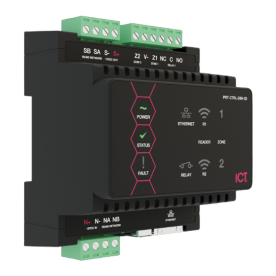
- Page 1 PRT-CTRL-DIN-1D Protege GX DIN Rail Single Door Controller Installation Manual...
- Page 2 Protege® Logo are registered trademarks of Integrated Control Technology Limited. All other brand or product names are trademarks or registered trademarks of their respective holders. Copyright © Integrated Control Technology Limited 2003-2021. All rights reserved. Last Published: 07-Oct-21 12:13 PM PRT-CTRL-DIN-1D | Protege GX DIN Rail Single Door Controller | Installation Manual...
-
Page 3: Table Of Contents
EOL Resistor Value Options Duplex Inputs Trouble Inputs Outputs Configuration Configuring a Controller via the Web Interface Logging In for the First Time Creating a Secure Password Configuring the IP Address PRT-CTRL-DIN-1D | Protege GX DIN Rail Single Door Controller | Installation Manual... - Page 4 Hardware Configuration Setting the IP Address from a Keypad Temporarily Defaulting the IP Address Defaulting a Controller LED Indicators Power Indicator Status Indicator Fault Indicator PoE Power Indicator PRT-CTRL-DIN-1D | Protege GX DIN Rail Single Door Controller | Installation Manual...
- Page 5 Intruder Detection Maintenance Routine Peripheral Devices Testing Frequency Recommended Routine Maintenance Procedures European Standards UK PD 6662:2017 and BS 8243 FCC Compliance Statements Industry Canada Statement Disclaimer and Warranty PRT-CTRL-DIN-1D | Protege GX DIN Rail Single Door Controller | Installation Manual...
-
Page 6: Introduction
Single Door Controller Editions There are two editions of the PRT-CTRL-DIN-1D Controller: ⦁ The PRT-CTRL-DIN-1D can be supplied power from a 12V DC power supply connected to the N+ and N- terminals. ⦁ The PRT-CTRL-DIN-1D-POE can be supplied power from a 12V DC power supply connected to the N+ and N- terminals OR from a power over ethernet (PoE) router via the onboard ethernet terminal. -
Page 7: Installation Requirements
Installation Requirements This equipment is to be installed in accordance with: The product installation instructions ⦁ AS/NZS 2201.1 Intruder Alarm Systems ⦁ The Local Authority Having Jurisdiction (AHJ) ⦁ PRT-CTRL-DIN-1D | Protege GX DIN Rail Single Door Controller | Installation Manual... -
Page 8: Grounding Requirements
(RS-485 N+, N-, NA, NB) DIN Rail Enclosure Additional DIN Rail Enclosure(s) Controller Reader Expander Dialer’s Earth Ground Connection Input Expander Power Supply Output Expander AC Mains Wiring Earth Ground Link Connection PRT-CTRL-DIN-1D | Protege GX DIN Rail Single Door Controller | Installation Manual... - Page 9 Sector or Building #3 Note that the DIN rail enclosure earth terminal is connected to the power supply V- terminal. There must be only one single earth grounding point per system. PRT-CTRL-DIN-1D | Protege GX DIN Rail Single Door Controller | Installation Manual...
-
Page 10: Mounting
A Protege DIN rail module can be removed from the DIN rail mount using the following steps: Insert a flat blade screwdriver into the hole in the module tab clip. Lever the tab outwards and rotate the unit off the DIN rail mount. PRT-CTRL-DIN-1D | Protege GX DIN Rail Single Door Controller | Installation Manual... -
Page 11: Connections
A battery backup must be connected to the module network to provide a monitored supply. The battery plays an important role in power conditioning and provides a continuous source of power in the event of a power outage. Example 2A Power Supply Connection: PRT-CTRL-DIN-1D | Protege GX DIN Rail Single Door Controller | Installation Manual... - Page 12 When using multiple power supplies it is important to ensure that all ground connections (V-) are connected between all power supplies and that no power connections (V+) are connected between any power supplies. PRT-CTRL-DIN-1D | Protege GX DIN Rail Single Door Controller | Installation Manual...
-
Page 13: Auxiliary Outputs
Integrated Control Technology power supply or a 12V DC supply. Please refer to the values outlined in the Technical Specifications below for more details. PRT-CTRL-DIN-1D | Protege GX DIN Rail Single Door Controller | Installation Manual... -
Page 14: Encrypted Module Network
CAT5e / CAT6 are also supported for data transmission when using ground in the same cable (to a maximum length of 100m (328ft)) Warning: Unused wires in the cable must not be used to carry power to other devices. PRT-CTRL-DIN-1D | Protege GX DIN Rail Single Door Controller | Installation Manual... -
Page 15: End Of Line (Eol) Resistors
Battery fault conditions will activate the battery trouble input associated with the address assigned to the controller. PRT-CTRL-DIN-1D | Protege GX DIN Rail Single Door Controller | Installation Manual... -
Page 16: Ethernet 10/100 Network Interface
Ethernet 10/100 Switch Hub Connection: Temporary direct connections can be used for onsite programming by using a standard ethernet cable. Ethernet 10/100 Direct Connection: PRT-CTRL-DIN-1D | Protege GX DIN Rail Single Door Controller | Installation Manual... -
Page 17: Door Access Control
The shield connection must only be connected at one end of the cable in the metallic enclosure (frame grounded). All ICT readers are shipped with single LED mode set as default and are fully compatible with the Protege system, such as tSec Standard Readers, tSec Mini Readers, etc. -
Page 18: Rs-485 Reader Connection (Entry/Exit)
NA and NB terminals of the reader and a second 330 ohm EOL resistor must then be inserted between the source NA and NB terminals at the other end of the wiring. PRT-CTRL-DIN-1D | Protege GX DIN Rail Single Door Controller | Installation Manual... -
Page 19: Door Contact Connection
To use the lock output in conjunction with the onboard reader, the lock output for the door associated with the reader port must be configured to be the desired lock output on the controller. This is not configured by default. Typical Lock Output Connection: PRT-CTRL-DIN-1D | Protege GX DIN Rail Single Door Controller | Installation Manual... -
Page 20: Programming The Onboard Reader
REX Input, Port 1 REX Input, Port 1 The controller's onboard reader port supports an RS-485 reader interface, allowing ICT RS485 readers to be configured. This can be set in the Expanders | Reader Expanders menu. PRT-CTRL-DIN-1D | Protege GX DIN Rail Single Door Controller | Installation Manual... -
Page 21: Inputs
Protege field modules. Value 1 Value 2 Monitored Status No Resistor No Resistor Open, Closed Open, Closed, Tamper, Short Open, Closed, Tamper, Short Open, Closed, Tamper, Short PRT-CTRL-DIN-1D | Protege GX DIN Rail Single Door Controller | Installation Manual... -
Page 22: Duplex Inputs
Input Address Position Resistor Enabling duplex inputs will not change the programming of any existing inputs. These must be reprogrammed or rewired to match the new addressing scheme. PRT-CTRL-DIN-1D | Protege GX DIN Rail Single Door Controller | Installation Manual... -
Page 23: Trouble Inputs
Hardware Fault System CP001:29 System restarted Hardware Fault System CP001:30 PoE Connection Lost (PoE model only) Power Fault General CP001:31 Output Over-Current Failure (PoE model only) Power Fault General PRT-CTRL-DIN-1D | Protege GX DIN Rail Single Door Controller | Installation Manual... -
Page 24: Outputs
This output can be used to activate larger relays, sounders, lights, locks etc. Example Relay Connection: Warning: The relay outputs can switch to a maximum capacity of 7A. Exceeding this amount will damage the output. PRT-CTRL-DIN-1D | Protege GX DIN Rail Single Door Controller | Installation Manual... -
Page 25: Configuration
Choose a Password for the admin operator. The password cannot be blank or 'admin'. Verify Password. very secure password is recommended for the admin operator (see Creating a Secure Password). PRT-CTRL-DIN-1D | Protege GX DIN Rail Single Door Controller | Installation Manual... -
Page 26: Creating A Secure Password
Programming the IP address, subnet mask, and default gateway requires knowledge of the network and subnet that the system is connected to. You should always consult the network or system administrator before programming these values. PRT-CTRL-DIN-1D | Protege GX DIN Rail Single Door Controller | Installation Manual... -
Page 27: Setting Up Integrated Ddns
Enter the Username and Password that you used to sign up to No-IP. Save your settings. Confirm that the controller is externally accessible by browsing to the hostname on another PC. PRT-CTRL-DIN-1D | Protege GX DIN Rail Single Door Controller | Installation Manual... -
Page 28: Setting Up An Https Connection
For older controllers not equipped with a default certificate, ICT strongly recommends that all live Protege sites establish an HTTPS connection between the controller web interface and the web browser. This is especially important if the controller can be accessed on-site via a router, or externally via the internet. - Page 29 Note: The default gateway must be set to the router's internal IP address that identifies it on the local internal network, not the external IP address used to connect over the internet. PRT-CTRL-DIN-1D | Protege GX DIN Rail Single Door Controller | Installation Manual...
- Page 30 Ensure that the Common Name is the same as the Domain Name which is being used for the controller, if any. PRT-CTRL-DIN-1D | Protege GX DIN Rail Single Door Controller | Installation Manual...
- Page 31 When using a self-signed certificate, you will likely be presented with a security warning if you attempt to access the HTTPS web page. The connection is still encrypted, but the browser has flagged the certificate as untrustworthy as it lacks third-party validation. PRT-CTRL-DIN-1D | Protege GX DIN Rail Single Door Controller | Installation Manual...
-
Page 32: Signing In
IMPORTANT: If this field is set to no value (which is converted to an invalid 0 value), the controller will no longer be accessible via the web interface and will require defaulting the IP address in order to connect. PRT-CTRL-DIN-1D | Protege GX DIN Rail Single Door Controller | Installation Manual... - Page 33 For older controllers not equipped with a default certificate, ICT strongly recommends that all live Protege sites establish an HTTPS connection between the controller web interface and the web browser. This is especially important if the controller can be accessed onsite via a router, or externally via the internet.
-
Page 34: Operators
Use HTTPS: ICT controllers come preconfigured with a pre-loaded certificate and HTTPS enabled by default, ⦁ however an alternate certificate can be installed if preferred. HTTPS Port*: The default port is 443. This can be changed to any port that is not occupied. -
Page 35: Application Software
This option should only be selected at the direction of ICT Technical Support . Click Upload Firmware to browse to the firmware file (.bin format) supplied by ICT, and open the file to install the firmware on the selected module. -
Page 36: Configuring A Controller Via The Protege Gx Software
Controller output 2 only exists on legacy hardware. This address is skipped when the wizard automatically adds the default records. Add Trouble Inputs: Enable this option to automatically add the trouble inputs associated with the controller. ⦁ PRT-CTRL-DIN-1D | Protege GX DIN Rail Single Door Controller | Installation Manual... -
Page 37: Adding A Controller Based On An Existing Controller
If the original records included the controller's name, this name will still be included in the new records (i.e. will not be replaced by the new name). PRT-CTRL-DIN-1D | Protege GX DIN Rail Single Door Controller | Installation Manual... -
Page 38: Configuring A Controller
Control and Status Request Port: This field specifies the port that will be used to send manual commands and status requests to the controller over TCP/IP. By default, this is port 21001. PRT-CTRL-DIN-1D | Protege GX DIN Rail Single Door Controller | Installation Manual... - Page 39 UDP protocol. This field defines the UDP port that will be used for these communications. The default port is 9450. If this port is changed at the controller it must also be updated at all relevant modules. PRT-CTRL-DIN-1D | Protege GX DIN Rail Single Door Controller | Installation Manual...
- Page 40 Version 3 Settings This section displays settings which were used in software version 3 and earlier. These settings do not require configuration in version 4 or later. PRT-CTRL-DIN-1D | Protege GX DIN Rail Single Door Controller | Installation Manual...
- Page 41 Backup Only Alarm Events: With this option enabled, when the controller has lost ethernet connection it will only report alarms and other reportable events over the phone line. All stored events will be reported when the ethernet link is restored. PRT-CTRL-DIN-1D | Protege GX DIN Rail Single Door Controller | Installation Manual...
- Page 42 Parity Type: The method of calculating the parity for the block. This is either even or odd parity. ⦁ Parity Location: The position of the parity bit in the received data. The count starts at zero. ⦁ PRT-CTRL-DIN-1D | Protege GX DIN Rail Single Door Controller | Installation Manual...
- Page 43 Card Data AES Encryption Key: Salto SALLIS and Aperio cards can be encoded with site/card information via ⦁ the ICT Encoder Client. This field defines the decryption key so that Protege GX can decrypt data from these cards. For more information, see...
- Page 44 For some modules, such as keypads, the network address can be set in the module itself (see the relevant installation manual). For most Protege modules the address is set in the Module Addressing window. PRT-CTRL-DIN-1D | Protege GX DIN Rail Single Door Controller | Installation Manual...
- Page 45 Once all modules are online and registered with the desired addresses the addressing process is complete. Legacy Protege PCB modules cannot be addressed by this process. They must be addressed using DIP switches as described in the relevant installation manual. PRT-CTRL-DIN-1D | Protege GX DIN Rail Single Door Controller | Installation Manual...
- Page 46 Physically disconnecting the readers alleviates the possibility of the firmware update failing due to the expander/controller receiving a packet on the RS-485 line while the update is in progress. PRT-CTRL-DIN-1D | Protege GX DIN Rail Single Door Controller | Installation Manual...
-
Page 47: Troubleshooting Controller Connectivity
If any service is not running, right click on it and click Start. If any services will not start there may be another issue with your installation. For example, the database version may be incompatible (see page 50). PRT-CTRL-DIN-1D | Protege GX DIN Rail Single Door Controller | Installation Manual... -
Page 48: Confirm Controller Ip Address
If you have two controllers with the same IP address or serial number anywhere on your server, there will be communication problems with at least one of them. PRT-CTRL-DIN-1D | Protege GX DIN Rail Single Door Controller | Installation Manual... -
Page 49: Confirm The Event Server Is Functioning
Control and Status Request Port (default 21001) In the controller web interface, on the Settings page, ensure that the Download Port and Control Port match those defined in the software. PRT-CTRL-DIN-1D | Protege GX DIN Rail Single Door Controller | Installation Manual... -
Page 50: Check Computer Name
When the controller and server are on the same local network the only place a firewall can be blocking messages is on the server machine itself. This is called the Windows Firewall. PRT-CTRL-DIN-1D | Protege GX DIN Rail Single Door Controller | Installation Manual... -
Page 51: Multiple Firewalls
Add the following executables, one by one: GXSV.exe GXSV2.exe GXSV3.exe GXPI.exe GXEvtSvr.exe GXDVR1.exe GXDVR2.exe This allows the Protege GX services access through the Firewall. Multiple Firewalls On corporate networks there can be multiple firewalls. PRT-CTRL-DIN-1D | Protege GX DIN Rail Single Door Controller | Installation Manual... -
Page 52: Encryption
This ensures that neither is encrypted and rules this out as a cause of communications problems. Encryption should then be re-enabled once communications are established. PRT-CTRL-DIN-1D | Protege GX DIN Rail Single Door Controller | Installation Manual... -
Page 53: Telnet
If the server is able to accept connections, the clear screen and blinking cursor appear. If the server is not reachable, a message will advise there is still a problem, indicating a firewall is blocking port 22000 to the server. PRT-CTRL-DIN-1D | Protege GX DIN Rail Single Door Controller | Installation Manual... -
Page 54: Hardware Configuration
Connect a wire link between NA of the module network and SA of the reader network, and between NB of the module network and SB of the reader network. Connect Input 2 to ground. PRT-CTRL-DIN-1D | Protege GX DIN Rail Single Door Controller | Installation Manual... -
Page 55: Defaulting A Controller
Connect a wire link between NA of the module network and SA of the reader network, and between NB of the module network and SB of the reader network. Connect Input 1 to ground. PRT-CTRL-DIN-1D | Protege GX DIN Rail Single Door Controller | Installation Manual... - Page 56 Reset the controller's IP address to its previous value. Reconfigure any additional network settings. Reinstall previously installed custom HTTPS certificates. Restore any other system settings as required by your site configuration. PRT-CTRL-DIN-1D | Protege GX DIN Rail Single Door Controller | Installation Manual...
-
Page 57: Led Indicators
PoE models only The PoE power indicator shows the status of the PoE connection. State Description On (green) PoE+ connection applied Flashing (green) PoE connection applied No PoE connection applied PRT-CTRL-DIN-1D | Protege GX DIN Rail Single Door Controller | Installation Manual... -
Page 58: Battery Indicator
A LONG flash (>1 second) indicates that the unit has read the data and the format was correct (red) Relay Indicator The relay indicator shows the status of the lock output relay. State Description On (red) Relay output is ON Relay output is OFF PRT-CTRL-DIN-1D | Protege GX DIN Rail Single Door Controller | Installation Manual... -
Page 59: Input Indicators
Input is in an open state Constantly on (green) Input is in a closed state Continuous flash (red) Input is in a tamper state Continuous flash (green) Input is in a short state PRT-CTRL-DIN-1D | Protege GX DIN Rail Single Door Controller | Installation Manual... -
Page 60: Mechanical Diagram
Mechanical Diagram The mechanical diagram shown below outlines the essential details needed to help ensure the correct installation of the controller. PRT-CTRL-DIN-1D | Protege GX DIN Rail Single Door Controller | Installation Manual... -
Page 61: Mechanical Layout
The mechanical layout shown below outlines the essential details needed to help ensure correct installation and mounting. All measurements are shown in millimeters. 78.40 Front 78.40 39.20 39.20 Back 67.18 PRT-CTRL-DIN-1D | Protege GX DIN Rail Single Door Controller | Installation Manual... -
Page 62: Technical Specifications
Dimensions (L x W x H) 78 x 90 x 60mm (3.07 x 3.54 x 2.36") Net Weight 170g (6oz) 210g (7.4oz) Gross Weight 230g (8.1oz) 310g (10.9oz) Operating Conditions PRT-CTRL-DIN-1D | Protege GX DIN Rail Single Door Controller | Installation Manual... - Page 63 N+ N- input terminals, and the maximum current is governed by the trip level of these fuses. The ICT implementation of OSDP conforms to a subset of the OSDP functionality. For specifications and reader configuration, refer to AN-254 Configuring OSDP Readers, available from the ICT website.
-
Page 64: New Zealand And Australia
In contrast, sites where automated testing functions have been implemented may find that annual maintenance visits are adequate. PRT-CTRL-DIN-1D | Protege GX DIN Rail Single Door Controller | Installation Manual... -
Page 65: Recommended Routine Maintenance Procedures
Note: When the mains power is restored following an AC fail condition, charge voltage the battery charge voltage may fluctuate between 10.0 - 13.8 VDC while the battery is recharging. PRT-CTRL-DIN-1D | Protege GX DIN Rail Single Door Controller | Installation Manual... - Page 66 Record and report any discrepancies. Special testing equipment and procedures may be required for smoke, heat, seismic glass-break and other detectors. PRT-CTRL-DIN-1D | Protege GX DIN Rail Single Door Controller | Installation Manual...
- Page 67 Record these in the maintenance sheets modifications and report. At the conclusion of Obtain client sign Obtain the signature of the client or the client's representative on each maintenance the maintenance record. visit PRT-CTRL-DIN-1D | Protege GX DIN Rail Single Door Controller | Installation Manual...
-
Page 68: European Standards
SP6 (LAN – Ethernet) and DP1 (LAN – Ethernet + PSTN) Tests EMC (operational) according to EN 55032:2015 Radiated disturbance EN 55032:2015 Power frequency magnetic field immunity tests (EN 61000-4-8) PRT-CTRL-DIN-1D | Protege GX DIN Rail Single Door Controller | Installation Manual... -
Page 69: Uk Pd 6662:2017 And Bs 8243
Warning: Enclosures supplied by 3rd parties may not be EN50131-compliant, and should not be claimed as such. UK PD 6662:2017 and BS 8243 Protege systems conform to PD 6662:2017 and BS 8243 at the security grade and notification option applicable to the system. PRT-CTRL-DIN-1D | Protege GX DIN Rail Single Door Controller | Installation Manual... -
Page 70: Fcc Compliance Statements
NOTE: THE GRANTEE IS NOT RESPONSIBLE FOR ANY CHANGES OR MODIFICATIONS NOT EXPRESSLY APPROVED BY THE PARTY RESPONSIBLE FOR COMPLIANCE. SUCH MODIFICATIONS COULD VOID THE USER’S AUTHORITY TO OPERATE THE EQUIPMENT. PRT-CTRL-DIN-1D | Protege GX DIN Rail Single Door Controller | Installation Manual... -
Page 71: Industry Canada Statement
Industry Canada Statement ICES-003 This is a Class A digital device that meets all requirements of the Canadian Interference Causing Equipment Regulations. CAN ICES-3 (A)/NMB-3 (A) PRT-CTRL-DIN-1D | Protege GX DIN Rail Single Door Controller | Installation Manual... -
Page 72: Disclaimer And Warranty
Integrated Control Technology Ltd nor its employees shall be liable under any circumstances to any party in respect of decisions or actions they may make as a result of using this information. In accordance with the ICT policy of enhanced development, design and specifications are subject to change without notice. - Page 73 In accordance with the ICT policy of enhanced development, design and specifications are subject to change without notice.
Need help?
Do you have a question about the PRT-CTRL-DIN-1D and is the answer not in the manual?
Questions and answers