Table of Contents
Advertisement
Quick Links
Advertisement
Table of Contents

Subscribe to Our Youtube Channel
Related Manuals for ICT Protege SE


Summary of Contents for ICT Protege SE
- Page 1 Protege SE Integrated System Controller Installation Manual...
- Page 2 Protege® and the Protege® Logo are registered trademarks of Integrated Control Technology Limited. All other brand or product names are trademarks or registered trademarks of their respective holders. Copyright © Integrated Control Technology Limited 2003-2016. All rights reserved. Publication Date: June 2017 PRT-CTRL-SE Protege SE Integrated System Controller Installation Manual | June 2017...
-
Page 3: Table Of Contents
3.1 UL/ULC Installation Cabinet Options ................8 Connections ______________________________________________________________ 9 4.1 Protege SE Integrated System Controller Connection ..........9 4.2 Wiring .......................... 10 4.3 Cabinet Enclosure Tamper Switch ................10 4.4 Earth Ground Connection .................... 10 4.5 ... - Page 4 16.1 Central Station Signal Receiver Compatibility List ............46 16.2 ULC Compliance Requirements .................. 46 CAN/ULC-S304-06 ...................... 46 CAN/ULC-S319-05 ...................... 49 CAN/ULC-S559-04 ...................... 49 16.3 UL Compliance Requirements ..................53 UL1610 ........................53 PRT-CTRL-SE Protege SE Integrated System Controller Installation Manual | June 2017...
- Page 5 FCC Compliance Statements ______________________________________________ 56 Industry Canada Statement ________________________________________________ 58 Ordering Information ______________________________________________________ 59 Warranty ________________________________________________________________ 60 Contact _________________________________________________________________ 61 PRT-CTRL-SE Protege SE Integrated System Controller Installation Manual | June 2017...
-
Page 6: Introduction
Introduction Thank you for purchasing the Protege SE Integrated System Controller by ICT. The Protege System is an advanced technology security system designed to provide integration with building automation, apartment complex control and HVAC in one flexible package. Communication is over a proprietary high speed protocol across an encrypted local area network and AES Encrypted Proprietary RS-485 module network. -
Page 7: Installation Requirements
CAN/ULC-S561, Installation and Services for Fire Signal Receiving Centres and Systems The National Electrical Code, ANSI/NFPA 70 The Canadian Electrical Code, Part I, CSA C22.1 The Local Authority Having Jurisdiction (AHJ) PRT-CTRL-SE Protege SE Integrated System Controller Installation Manual | June 2017... -
Page 8: Mounting
Electronic Access Control System Installations All cabinet installations of this type must be located inside the Protected Area. Cabinet Model Manufacturer UL/ULC Installation Listings CAB-LARGE-UL UL294, CAN/ULC-S319 D8108A Bosch UL294, CAN/ULC-S319 PRT-CTRL-SE Protege SE Integrated System Controller Installation Manual | June 2017... -
Page 9: Connections
*When installed with the power supply manufactured by Marcus (Model M4758CT), the Digital Security Controls (DSC) Model ULC-LA power indicator light assembly (Installation Instruction No. 29001877 R0) must be installed within a conduit knockout of the ICT Model CAB-LARGE-UL or Bosch Model D8108A Next modules enclosure in order to provide green AC power on indication. -
Page 10: Wiring
Cold water pipe grounding earth peg grounding rod To other earth connec ons already a ached to the earth peg or water pipe Earth Ground Connection PRT-CTRL-SE Protege SE Integrated System Controller Installation Manual | June 2017... -
Page 11: Ac Power
Digital Security Controls (DSC) Model ULC-LA power indicator light assembly (Installation Instruction No. 29001877 R0) must be installed within a conduit knockout of either the ICT Model CAB-LARGE-UL or Bosch Model D8108A enclosure in order to provide green AC power on indication. -
Page 12: Battery Backup
Controller to any other ancillary device (siren, lock or mag clamp etc). Connection may cause erroneous faults or serious damage to the Controller and will VOID ALL WARRANTIES OR GUARANTEES. PRT-CTRL-SE Protege SE Integrated System Controller Installation Manual | June 2017... -
Page 13: Battery Charge Current Setting
Controller status outside the enclosure. The following diagrams show the connection of an LED indicator to the status output. +12V AUX 1K5 OHM External Status LED Connection PRT-CTRL-SE Protege SE Integrated System Controller Installation Manual | June 2017... -
Page 14: Encrypted Module Network
Total combined current are ALL lower or equal to the values outlined in the Technical Specifications section. If these currents are exceeded, a separate power supply shall be used. PRT-CTRL-SE Protege SE Integrated System Controller Installation Manual | June 2017... - Page 15 EOL OFF EOL ON EOL Jumper The EOL (End Of Line) jumper setting must be set in the on position for the first and last expansion device only. PRT-CTRL-SE Protege SE Integrated System Controller Installation Manual | June 2017...
-
Page 16: Telephone Dialer
Controller. Pay attention to the key location of the 40 Way connector. 40 Way Expansion Connector Daughter Board Main System Controller Connection and Mounting PRT-CTRL-SE Protege SE Integrated System Controller Installation Manual | June 2017... -
Page 17: Ethernet 10/100 Network Interface
When installing an Ethernet connection the Protege System Controller shall be interfaced using a standard segment (<100m in length) and shall be connected to a suitable Ethernet hub or switch. Ethernet 10/100 Switch hub Connection PRT-CTRL-SE Protege SE Integrated System Controller Installation Manual | June 2017... - Page 18 UL and ULC standard requirements associated with a signal receiving center. The Protege System Controller must be installed in the same room as the network equipment that provides it the network connection. PRT-CTRL-SE Protege SE Integrated System Controller Installation Manual | June 2017...
-
Page 19: Door Access Control
LED mode. Refer to your card reader documentation for further details. Compatible access control card reader communication formats are: 26-, 34-, 37-Bit Wiegand, RS-232, RS-485, and Smart RS-485. PRT-CTRL-SE Protege SE Integrated System Controller Installation Manual | June 2017... -
Page 20: Multiple Wiegand Card Reader Connection
Do not connect the shield to a AUX- or 0V connection. Do not join the shield and black wires at the reading device. Do not connect the shield to any shield used for isolated communication. PRT-CTRL-SE Protege SE Integrated System Controller Installation Manual | June 2017... -
Page 21: Door Contact Connection
When connected, the REX Input can be programmed to operate regardless of the door contact state. The REX input can also be programmed to recycle the door alarm time to prevent nuisance alarms when the door is held open to permit longer entry. PRT-CTRL-SE Protege SE Integrated System Controller Installation Manual | June 2017... -
Page 22: Lock Output Connection
Alternatively, these can be disabled from the keypad by logging in as an installer and selecting Menu, 4, 1, 4, RD004. REX and REN devices must be Listed to UL 294 for UL installations and CAN/ULC-S319 for ULC installations, and be compatible with the system. PRT-CTRL-SE Protege SE Integrated System Controller Installation Manual | June 2017... - Page 23 REX Input, Port 2 REX Input, Port 2 Zone 15 Bond Sense, Port 2 General Purpose Zone Zone 16 REN Input, Port 2 General Purpose Zone Reader Expander Properties PRT-CTRL-SE Protege SE Integrated System Controller Installation Manual | June 2017...
-
Page 24: Inputs
The zones 9-12 and 13-16 can operate as either general purpose zone inputs or as onboard reader inputs. If used as general purpose zone inputs then make sure that these inputs are not defined in the onboard reader set up. PRT-CTRL-SE Protege SE Integrated System Controller Installation Manual | June 2017... -
Page 25: Resistor Value Options
No Resistors Open, Closed Open, Closed, Tamper, Short Open, Closed, Tamper, Short Open, Closed, Tamper, Short Open, Closed, Tamper, Short Open, Closed, Tamper, Short Open, Closed, Tamper, Short PRT-CTRL-SE Protege SE Integrated System Controller Installation Manual | June 2017... -
Page 26: Trouble Zones
CP001:25 Service 2 Stopped Hardware Fault System CP001:26 Service 3 Stopped Hardware Fault System CP001:27 Service 4 Stopped Hardware Fault System CP001:28 Reserved | | | | CP001:64 Reserved PRT-CTRL-SE Protege SE Integrated System Controller Installation Manual | June 2017... -
Page 27: Programmable Outputs
Connecting a Piezo siren may result in a dull noise being emitted. This is caused by residual current from the monitoring circuit. To prevent this occurring, connect 2 1K resistors in parallel. PRT-CTRL-SE Protege SE Integrated System Controller Installation Manual | June 2017... -
Page 28: Pgm 3/4 Outputs
PGMs. These can be controlled by assigning the RDxxxGreen R1, RDxxx Beeper R1, RDxxxGreen R2 and RDxxx Beeper R2 PGMs of whichever reader module has been configured as the onboard reader module. 1K5 OHM Reader PGMs PRT-CTRL-SE Protege SE Integrated System Controller Installation Manual | June 2017... -
Page 29: Hardware Configuration
IP will be set to 192.168.111.222 while this switch remains on. Allows the connection and review of the programmed IP address or the modification to another setting. Switch Switch Function System Default Normal Operation Factory Default Protege Controller PRT-CTRL-SE Protege SE Integrated System Controller Installation Manual | June 2017... -
Page 30: Defaulting A Controller
The system will now be defaulted with all programming and settings returned to factory configuration. Defaulting the Controller does not reset the IP address. To reset an IP address, refer to the details on the Configuration Switch (see page 29). PRT-CTRL-SE Protege SE Integrated System Controller Installation Manual | June 2017... -
Page 31: Led Indicators
The module communicates using an isolated RS-485 interface for optimal performance and this requires an isolated supply on the N+ and N- terminals of the module network interface. When a valid supply is input, the 5V ISO indicator will illuminate. PRT-CTRL-SE Protege SE Integrated System Controller Installation Manual | June 2017... -
Page 32: Bell 1/Bell 2 Indicators
9.12 Online Indicator The Online indicator is located near the center of the PCB and is labeled ONLINE. The Online indicator shows when the modem has control of the telephone line. PRT-CTRL-SE Protege SE Integrated System Controller Installation Manual | June 2017... -
Page 33: Mechanical Diagram
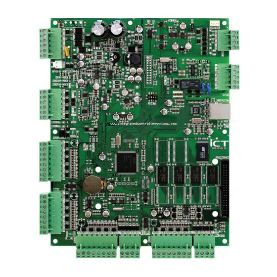
Zones 1 to 4 Coin Cell Ba ery Expansion Interface Zones 5 to 8 Zones 9 to 12 Reader Port 1 Zones 13 to 16 Reader Port 2 Mechanical Diagram PRT-CTRL-SE Protege SE Integrated System Controller Installation Manual | June 2017... -
Page 34: Mechanical Layout
The mechanical layout shown below outlines the essential details needed to help ensure the correct installation of the Protege Controller. 183mm 175mm 76.5mm 98.5mm 5mm diameter PRT-CTRL-SE 93.5mm 81.5mm Mechanical Layout PRT-CTRL-SE Protege SE Integrated System Controller Installation Manual | June 2017... -
Page 35: System Capacities
Zone Types Door Types Services Phone Numbers Schedules Holidays Daylight Saving Adjustment Settings Automation Points Panel Configuration Information Area Names Access Level Names Zone Type Names Zone Names 1136 1104 PRT-CTRL-SE Protege SE Integrated System Controller Installation Manual | June 2017... - Page 36 1024 1024 1024 1024 Programmable Function Elevator Car Groups Elevator Car Group Names Variable Bit variable Door Schedules Floor Schedules The Elevator profile has not been evaluated by UL/ULC. PRT-CTRL-SE Protege SE Integrated System Controller Installation Manual | June 2017...
-
Page 37: Technical Specifications
Integrated Control Technology continually strives to increase the performance of its products. As a result these specifications may change without notice. We recommend consulting the ICT website (http://www.ict.co) for the latest documentation and product information. -
Page 38: Current And Validation Example 1
Is B1 current output less or equal to 1.1A (1100mA)? Yes, it is 1.1A (1100mA) Is the total combined current less or equal to 1.7A (1700mA)? Yes, it is 1.69A (1690mA) PRT-CTRL-SE Protege SE Integrated System Controller Installation Manual | June 2017... -
Page 39: Current And Validation Example 2
350mA or 700mA 40VA/100VA 1 x 12VDC, 7Ah UL 294 and 1400mA 350mA or 700mA 100VA CAN/ULC-S319, 4hr backup 2 x 12VDC, 7Ah = 2000mA 350mA or 700mA 100VA 14Ah PRT-CTRL-SE Protege SE Integrated System Controller Installation Manual | June 2017... -
Page 40: Current And Validation (Ul Installation) Example 1
Total Combined Current Available 1.7A (1700mA) Operating Current 120mA (Typical) Battery Charging 350mA (Standard Current Charging) DC Output (AUX1) PRT-KLCD Protege Alphanumeric LCD Keypad (30mA Typical) Total Consumption 0.5A (500mA) PRT-CTRL-SE Protege SE Integrated System Controller Installation Manual | June 2017... -
Page 41: Current And Validation (Ul Installation) Example 2
DC Output (AUX2) PRX-NPROX Nano Prox Card Reader (120mA @ 13.8VDC) B1 Output Electric Locking Device (520mA @ 13.8VDC) B2 Output Electric Locking Device (520mA @ 13.8VDC) Total Consumption 2.1A (2100mA) PRT-CTRL-SE Protege SE Integrated System Controller Installation Manual | June 2017... - Page 42 Is B2 current output less or equal to 1.1A (1100mA)? Yes, it is 520mA Is the total combined current less or equal to 2.5A (2500mA)? Yes, it is 2.1A (2100mA) PRT-CTRL-SE Protege SE Integrated System Controller Installation Manual | June 2017...
-
Page 43: New Zealand And Australia
14 New Zealand and Australia General Product Statement The RCM compliance label indicates that the supplier of the device asserts that it complies with all applicable standards. PRT-CTRL-SE Protege SE Integrated System Controller Installation Manual | June 2017... -
Page 44: European Standards
Access class B EN 50133-1:1998 ICT enclosure all products, CAB-JMB-NOT, has been tested and certified to EN50131. By design, the ICT enclosure for all products, CAB-FBY-NOT, complies with the EN50131 standards. Tamper protection against removal of the cover as well as removal from mounting is provided by tamper switch. - Page 45 Remote LED Disable input. To comply with EN 50131: Only one battery can be connected and monitored per system. If more capacity is required, a single, larger battery must be used. PRT-CTRL-SE Protege SE Integrated System Controller Installation Manual | June 2017...
-
Page 46: Ul And Ulc Installation Requirements
Protege System Controller Reference Manual (227-4045-500) Central Station Signal Receiver The common equipment of each signal receiving center control unit shall be limited to 1000 alarm systems. PRT-CTRL-SE Protege SE Integrated System Controller Installation Manual | June 2017... - Page 47 Network access policies should be set to restrict unauthorized network access and "spoofing" or "denial of service" attacks. Ethernet Connections All Ethernet network connections shall be installed within the same room as the equipment. PRT-CTRL-SE Protege SE Integrated System Controller Installation Manual | June 2017...
- Page 48 Group Code as defined in the Details settings on the Ademco 685 tab of the Preferences Menu Point Code as defined in the Details settings on the Ademco 685 tab of the Preferences Menu PRT-CTRL-SE Protege SE Integrated System Controller Installation Manual | June 2017...
-
Page 49: Can/Ulc-S319-05
The Digital Security Controls (DSC) Model ULC-LA power indicator light assembly (Installation Instruction No. 29001877 R0) must be installed within a conduit knockout of either the ICT Model CAB-LARGE-UL or Bosch Model D8108A enclosure in order to provide green AC power on indication. - Page 50 The Digital Security Controls (DSC) Model ULC-LA power indicator light assembly (Installation Instruction No. 29001877 R0) must be installed within a conduit knockout of either the ICT Model CAB-LARGE-UL or Bosch Model D8108A enclosure in order to provide green AC power on indication.
- Page 51 Open, Close, Tamper, Short Open, Close, Tamper, Short Open, Close, Tamper, Short Open, Close, Tamper, Short * EOL resistor must be installed at the Fire Alarm Control Panel Output. PRT-CTRL-SE Protege SE Integrated System Controller Installation Manual | June 2017...
- Page 52 Protege System Controller Reference Manual (227-4045-500). Fire zones Z1-Z3 shall be used exclusively for fire monitoring and cannot be programmed to activate bell outputs (B1/B2). PRT-CTRL-SE Protege SE Integrated System Controller Installation Manual | June 2017...
-
Page 53: Ul Compliance Requirements
Protege System Controller Reference Manual (227-4045-500). The Trouble Zone Area must be armed in 24h mode. Refer to the section 24HR Enabling in the Protege System Controller Reference Manual (227-4045-500). PRT-CTRL-SE Protege SE Integrated System Controller Installation Manual | June 2017... -
Page 54: Ul294
The Digital Security Controls (DSC) Model ULC-LA power indicator light assembly (Installation Instruction No. 29001877 R0) must be installed within a conduit knockout of either the ICT Model CAB-LARGE-UL or Bosch Model D8108A enclosure in order to provide green AC power on indication. - Page 55 The Digital Security Controls (DSC) Model ULC-LA power indicator light assembly (Installation Instruction No. 29001877 R0) must be installed within a conduit knockout of either the ICT Model CAB-LARGE-UL or Bosch Model D8108A enclosure in order to provide green AC power on indication.
-
Page 56: Fcc Compliance Statements
FCC Part 68 rules and requirements adopted by the ACTA. A compliant telephone cord modular plug is provided with this product. It is designed to be connected to a compatible modular jack that is also compliant. See this document for details. PRT-CTRL-SE Protege SE Integrated System Controller Installation Manual | June 2017... - Page 57 Customer Premises Equipment and Wiring Network Service Provider's Computer RJ-31X Facilities Jack Unused Alarm Dialing RJ-11 Jack Equipment Telephone Line Telephone Network Unused Demarcation Fax Machine RJ-11 Jack Telephone Point Answering System Telephone PRT-CTRL-SE Protege SE Integrated System Controller Installation Manual | June 2017...
-
Page 58: Industry Canada Statement
à la seule condition que la somme d’indices d’équivalence de la sonnerie de tous les dispositifs n’excède pas 5. PRT-CTRL-SE REGISTRATION NUMBER IC: 10012A-PRTCTRL PRT-CTRL-SE NUMÉRO D'ENREGISTREMENT IC: 10012A-PRTCTRL PRT-CTRL-SE Protege SE Integrated System Controller Installation Manual | June 2017... -
Page 59: Ordering Information
19 Ordering Information Please use the following product codes when placing an order for the Protege SE Integrated System Controller. PRT-CTRL-SE Manuals and additional literature are available on the ICT Website (http://www.ict.co). PRT-CTRL-SE Protege SE Integrated System Controller Installation Manual | June 2017... -
Page 60: Warranty
ICT's obligation and liability under this warranty is expressly limited to repairing or replacing, at ICT's option, any product not meeting the specifications. In no event shall ICT be liable to the buyer or any other person for any loss or damages whether direct or indirect or consequential or... -
Page 61: Contact
21 Contact Integrated Control Technology welcomes all feedback. Please visit our website (http://www.ict.co) or use the contact information below. Integrated Control Technology P.O. Box 302-340 4 John Glenn Ave North Harbour Post Centre Rosedale Auckland North Shore City 0632 New Zealand... - Page 62 Integrated Control Technology Limited 4 John Glenn Avenue, Rosedale, Auckland 0632 PO Box 302-340, North Harbour, Auckland 0751, New Zealand Email: sales@ict.co Toll Free: (0800) 428 111 Phone: 64 (9) 476 7124 AMERICAS Integrated Control Technology (USA) LLC 5265 S Rio Grande Street, Suite 201, Littleton, CO 80120 Email: ussales@ict.co Toll Free: (855) 428 9111 Phone: 720 442 0767...
Need help?
Do you have a question about the Protege SE and is the answer not in the manual?
Questions and answers