Table of Contents
Advertisement
Quick Links
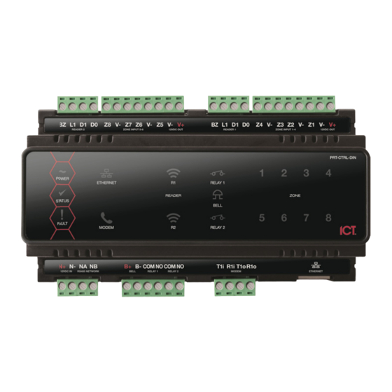
Protege GX D
DIN Rail
Integrated System
m Controller
Quick Start
t Guide
1. Introduct
tion
Thank you for p
purchasing the Protege
e GX DIN Rail Integra
System Control
ler by Integrated Cont
trol Technology. The C
is the central pro
ocessing unit of the Pr
rotege System. It comm
with all system
modules, stores all co
onfiguration and transa
information, pro
ocesses all system com
mmunication, and repo
alarms and syst
tem activity to a monit
toring station or remot
computer.
When receiving
g the GX Integrated Sy
ystem Controller you s
the kit contains
the items listed below
w. Please note that if y
have the correc
ct contents, you should
d contact your distribu
immediately.
Protege GX
X DIN Rail Integrated
System Controller
18 1K ohm
m resistors
1 330 Ohm
m EOL Termination Re
esistor
1 Diode 1N
N4007 1A 400V (Axial
)
DIN Rail M
Mounting Strip
For more inform
mation on the Protege
GX DIN Rail Integrate
Controller and o
other Integrated Contr
rol Technology produc
login to www.inc
control.co.nz.
2. Power Require
ements
T
The Protege GX Integr
rated System Controlle
D
DC power supply conn
ected to the N+ and N
co
ontain internal regulat
ion or isolation. It is re
P
PRT-PSU-DIN is used
for this purpose. In a
sa
ame power supply can
n be used to supply th
w
well, so long as the ma
aximum load of the pow
ex
xceeded. If using the
PRT-PSU-DIN module
b
ackup and can be con
nnected to the module
monitored supply. Plea
m
ase refer to the PRT-P
m
manual for specific deta
ails of the connections
PRT-CTRL-DIN
N+
N-
NA
NB
To
o other modules
on network
ted
Controller
municates
action
orts
Examp
ple Power Supply Con
e
In
n larger installations, th
he power supply may
fo
or load sharing betwee
en several supplies.
should find
ou do not
Module #3
tor
N+
N-
NA
NB
Power Supply #3
Examp
ple multiple PSU Con
3. Card Reader C
Connection
ed System
cts please
T
The following diagram
shows the connection
R
Reader with the GX Int
tegrated System Contr
A
Access Door in Entry o
or Exit mode. The Con
d
ual LED reader mode
and readers must be
L
ED mode. Refer to yo
our card reader docum
d
etails.
er is supplied by a 12V
V
N- terminals. It does no
ot
commended that an IC
CT
small installation this
he module network as
wer supply is not
e, it can support batte
ry
e network to provide a
SU-DIN installation
s.
PRT-PSU-DIN
V1+ V1+ V1+ V1+ V1
1+
V1+
V-
V-
V-
V-
V-
V-
N+
N-
NA
NB
B-
L
N
B+
Gel Cell Backup Battery
Mains Input
-
+
nnection
need to be split to allo
ow
Module #2
Module #
#1
PRT-CTRL-DIN
N+
N-
NA
NB
N+
N-
NA
A
NB
N+
N-
NA
NB
Power Supply #2
Power Supply #1
nection
of a standard Wiegan
nd
roller controlling an
troller does not suppo
ort
configured for single
mentation for further
RED
BLACK
Shield
ded Cable
GREEN
WHITE
N/R
ORANGE
BROWN
Shield not
Sh
ield is frame
connected
grounded at
BLUE
one point
N/R
YELLOW
SHIELD
BZ
L1
D1
Card Rea
ader Connection
4. Doo
or Contact Conne
ection
The Prote
ege GX Integrated Sy
ystem Controller allows
of up to 4
4 contacts for monitori
ng and controlling acc
doors. Ea
ach input on the Contr
roller can be used for t
that is au
utomatically assigned a
and as a normal input
The follow
wing example shows t
the connection of a no
door pos
ition monitoring contac
ct to monitor the Open
and Alarm
m conditions of the do
oor.
N.C. Input Contact
1K
1K
N.O. Input Contact
N.C. Input Contact
1K
1K
N.O. Input Contact
Door Con
ntact Connection
Input
Function
Default Se
Input 1
Door Contact, Por
rt 1
Door Contact
Input 2
REX Input, Port 1
REX Input, Po
Input 3
Bond Sense, Port
1
General Purp
Input 4
REN Input, Port 1
General Purp
Input 5
Door Contact, Por
rt 2
Door Contact
Input 6
REX Input, Port 2
REX Input, Po
Input 7
Bond Sense, Port
2
General Purp
Input 8
REN Input, Port 2
General Purp
DO
Z4
V-
-
Z3
Z2
V-
Z1
V-
V+
s the connection
cess control
the door function
t on the system.
ormally closed
n, Closed, Forced
1K
REN Input
Bond Sense
1K
1K
REX Input
Door Contact
1K
etting
, Port 1
ort 1
pose Input
pose Input
, Port 2
ort 2
pose Input
pose Input
Advertisement
Table of Contents

Subscribe to Our Youtube Channel
Related Manuals for ICT Protege GX DIN Rail System Controller


Summary of Contents for ICT Protege GX DIN Rail System Controller
- Page 1 2. Power Require ements BLACK Shield ded Cable GREEN WHITE The Protege GX Integr rated System Controlle er is supplied by a 12V ORANGE DC power supply conn ected to the N+ and N N- terminals. It does no BROWN Shield not ield is frame ontain internal regulat...
- Page 2 5. Lock Output Connection 8. Telephone Dialer 10. Technical Specifications The GX Integrated System Controller provides the ability to The Protege GX Integrated System Controller provides a connection Operating Voltage 12V DC +- 10% communicate alarms and upload information to remote systems for one electric strike lock with full monitoring of the lock circuit for Operating Current 120mA (Typical)
Need help?
Do you have a question about the Protege GX DIN Rail System Controller and is the answer not in the manual?
Questions and answers