ICT PRT-WX-DIN Installation Manual
Protege wx din rail integrated system controller
Hide thumbs
Also See for PRT-WX-DIN:
- Programming reference manual (153 pages) ,
- End user manual (21 pages)
Table of Contents
Advertisement
Advertisement
Table of Contents

Related Manuals for ICT PRT-WX-DIN


Summary of Contents for ICT PRT-WX-DIN
- Page 1 PRT-WX-DIN Protege WX DIN Rail Integrated System Controller Installation Manual...
- Page 2 Copyright © Integrated Control Technology Limited 2003-2021. All rights reserved. Last Published: 25-May-21 4:29 PM PRT-WX-DIN | Protege WX DIN Rail Integrated System Controller | Installation Manual...
-
Page 3: Table Of Contents
RS-485 Reader Connection (Entry/Exit) Door Contact Connection Lock Output Connection Programming the Onboard Reader Inputs EOL Resistor Value Options Duplex Inputs Trouble Inputs Outputs Bell/Siren Output Relay Outputs Reader Outputs Configuration PRT-WX-DIN | Protege WX DIN Rail Integrated System Controller | Installation Manual... - Page 4 Temporarily Defaulting the IP Address Defaulting a Controller LED Indicators Power Indicator Status Indicator Fault Indicator Ethernet Link Indicator Modem Indicator Reader Data Indicators Bell Indicator Relay Indicators Input Indicators Mechanical Diagram PRT-WX-DIN | Protege WX DIN Rail Integrated System Controller | Installation Manual...
- Page 5 Central Station Signal Receiver Compatibility List UL Operation Mode ULC Compliance Requirements CAN/ULC-S304 CAN/ULC-S319 CAN/ULC-S559 UL Compliance Requirements UL1610 UL294 FCC Compliance Statements Industry Canada Statement Disclaimer and Warranty PRT-WX-DIN | Protege WX DIN Rail Integrated System Controller | Installation Manual...
-
Page 6: Introduction
⦁ Factory loaded HTTPS certificate ⦁ OSDP configurable RS-485 ⦁ 8 high security monitored inputs ⦁ Built-in offsite communications dialer (ContactID or SIA) ⦁ Industry standard DIN rail mounting ⦁ PRT-WX-DIN | Protege WX DIN Rail Integrated System Controller | Installation Manual... -
Page 7: Installation Requirements
The National Electrical Code, ANSI/NFPA 70 ⦁ The Canadian Electrical Code, Part I, CSA C22.1 ⦁ AS/NZS 2201.1 Intruder Alarm Systems ⦁ The Local Authority Having Jurisdiction (AHJ) ⦁ PRT-WX-DIN | Protege WX DIN Rail Integrated System Controller | Installation Manual... -
Page 8: Grounding Requirements
(RS-485 N+, N-, NA, NB) DIN Rail Enclosure Additional DIN Rail Enclosure(s) Controller Reader Expander Dialer’s Earth Ground Connection Input Expander Power Supply Output Expander AC Mains Wiring Earth Ground Link Connection PRT-WX-DIN | Protege WX DIN Rail Integrated System Controller | Installation Manual... - Page 9 Sector or Building #3 Note that the DIN rail enclosure earth terminal is connected to the power supply V- terminal. There must be only one single earth grounding point per system. PRT-WX-DIN | Protege WX DIN Rail Integrated System Controller | Installation Manual...
-
Page 10: Mounting
A Protege DIN rail module can be removed from the DIN rail mount using the following steps: Insert a flat blade screwdriver into the hole in the module tab clip. Lever the tab outwards and rotate the unit off the DIN rail mount. PRT-WX-DIN | Protege WX DIN Rail Integrated System Controller | Installation Manual... -
Page 11: Wiring Diagram
Input is in the TAMPERED state the Controller Installation Manual for instructions it's IP address. on programming the onboard reader. Flashing green Input is in the SHORTED state PRT-WX-DIN | Protege WX DIN Rail Integrated System Controller | Installation Manual... -
Page 12: Connections
A battery backup must be connected to the module network to provide a monitored supply. The battery plays an important role in power conditioning and provides a continuous source of power in the event of a power outage. Example 2A Power Supply Connection: PRT-WX-DIN | Protege WX DIN Rail Integrated System Controller | Installation Manual... - Page 13 When using multiple power supplies it is important to ensure that all ground connections (V-) are connected between all power supplies and that no power connections (V+) are connected between any power supplies. PRT-WX-DIN | Protege WX DIN Rail Integrated System Controller | Installation Manual...
-
Page 14: Auxiliary Outputs
CAT5e / CAT6 are also supported for data transmission when using ground in the same cable (to a ⦁ maximum length of 100m (328ft)) Warning: Unused wires in the cable must not be used to carry power to other devices. PRT-WX-DIN | Protege WX DIN Rail Integrated System Controller | Installation Manual... -
Page 15: End Of Line (Eol) Resistors
2400bps modem. The telephone line can be connected directly to the controller using the onboard telephone connection terminals. Telco line tip and ring input Telco line out PRT-WX-DIN | Protege WX DIN Rail Integrated System Controller | Installation Manual... -
Page 16: Ethernet 10/100 Network Interface
UL and ULC standard requirements associated with a signal receiving center. ⦁ The controller must be installed in the same room as the network equipment that provides it the network connection. PRT-WX-DIN | Protege WX DIN Rail Integrated System Controller | Installation Manual... -
Page 17: Door Access Control
The shield connection must only be connected at one end of the cable in the metallic enclosure (frame ⦁ grounded). All UL listed ICT readers are shipped with single LED mode set as default and are fully compatible with the Protege system, such as tSec Standard Readers, tSec Mini Readers, etc. Wiegand Reader Connection The controller allows the connection of 2 magnetic clock and data reading devices or 4 Wiegand reading devices and the ability to control 2 doors (entry or exit only) or 1 door (entry and exit). -
Page 18: Multiple Wiegand Reader Connection
Location Configuration Entry Green and orange wires not connected. Exit Green and orange wires connected together. PRT-WX-DIN | Protege WX DIN Rail Integrated System Controller | Installation Manual... -
Page 19: Rs-485 Reader Connection (Entry Only)
The following example shows the connection of a normally closed door position monitoring contact to monitor the open, closed, forced and alarm conditions of the door. PRT-WX-DIN | Protege WX DIN Rail Integrated System Controller | Installation Manual... -
Page 20: Lock Output Connection
The lock output is shared with the bell/siren function as shown in the diagram below. You can select another output for the lock control (Relay 1 (CP001:03) or Relay 2 (CP001:04)) if the bell/siren function is required. PRT-WX-DIN | Protege WX DIN Rail Integrated System Controller | Installation Manual... -
Page 21: Programming The Onboard Reader
Input 6 REX input, Port 2 REX Input, Port 2 Input 7 Bond Sense, Port 2 General Purpose Input Input 8 REN Input, Port 2 General Purpose Input PRT-WX-DIN | Protege WX DIN Rail Integrated System Controller | Installation Manual... -
Page 22: Inputs
When using the 'No Resistor' configuration the controller only monitors the opened and closed state of the connected input device, generating the alarm (open) and restore (closed/sealed) conditions. PRT-WX-DIN | Protege WX DIN Rail Integrated System Controller | Installation Manual... -
Page 23: Eol Resistor Value Options
To enable this feature, navigate to System | Settings and enter the following command: DuplexZones = true In addition, you will need to manually add additional inputs with addresses 9-16 in Programming | Inputs. PRT-WX-DIN | Protege WX DIN Rail Integrated System Controller | Installation Manual... -
Page 24: Trouble Inputs
These can then be used to report a message to a monitoring station, remote computer, keypad or siren. The following table details the trouble inputs that are configured in the controller and the trouble type and group that they activate. PRT-WX-DIN | Protege WX DIN Rail Integrated System Controller | Installation Manual... - Page 25 CP001:29 System restarted Hardware Fault System CP001:32 3G Modem Link Lost Hardware Fault System CP001:33 Controller Group Link Lost Hardware Fault System | | | | CP001:64 Reserved PRT-WX-DIN | Protege WX DIN Rail Integrated System Controller | Installation Manual...
- Page 26 CP001:33 Controller Group Link Lost is not evaluated by UL, cUL, ULC. PRT-WX-DIN | Protege WX DIN Rail Integrated System Controller | Installation Manual...
-
Page 27: Outputs
1K resistor (provided in the accessory bag) across the bell output. If the bell is not being used for another function, and the trouble input is not programmed in the system, a resistor is not required. PRT-WX-DIN | Protege WX DIN Rail Integrated System Controller | Installation Manual... -
Page 28: Relay Outputs
These are open drain outputs which switch to the V- reference. 1K5 OHM Warning: The reader outputs can switch to a maximum capacity of 50mA. Exceeding this amount will damage the output. PRT-WX-DIN | Protege WX DIN Rail Integrated System Controller | Installation Manual... -
Page 29: Configuration
As a guideline, a secure password should include these features: ⦁ Minimum 8 characters in length ⦁ Combination of upper and lower case letters ⦁ Combination of numbers and letters ⦁ Inclusion of special characters PRT-WX-DIN | Protege WX DIN Rail Integrated System Controller | Installation Manual... -
Page 30: Registering Your Controller
To Automatically Activate Your License: Click Download License. Your details are passed to the ICT web registration service, then your license is activated automatically. Important: The automatic activation process requires an internet connection on the workstation you are using to connect to the controller. If this is not available, you will need to use the manual activation option. -
Page 31: Configuring The Ip Address
Programming the IP address, subnet mask, and default gateway requires knowledge of the network and subnet that the system is connected to. You should always consult the network or system administrator before programming these values. PRT-WX-DIN | Protege WX DIN Rail Integrated System Controller | Installation Manual... -
Page 32: Setting Up Integrated Ddns
Enter the Username and Password that you used to sign up to No-IP. Save your settings. Confirm that the controller is externally accessible by browsing to the hostname on another PC. PRT-WX-DIN | Protege WX DIN Rail Integrated System Controller | Installation Manual... -
Page 33: Setting Up An Https Connection
For older controllers not equipped with a default certificate, ICT strongly recommends that all live Protege sites establish an HTTPS connection between the controller web interface and the web browser. This is especially important if the controller can be accessed on-site via a router, or externally via the internet. - Page 34 Note: The default gateway must be set to the router's internal IP address that identifies it on the local internal network, not the external IP address used to connect over the internet. PRT-WX-DIN | Protege WX DIN Rail Integrated System Controller | Installation Manual...
-
Page 35: Third-Party Certificate
It is recommended that you carefully note all requirements for your chosen CA before beginning. IT support should be consulted when obtaining and loading a third-party certificate. ICT Technical Support cannot assist with this process. - Page 36 Click Load Validation File and browse to the .txt validation file to load it onto the controller. Scroll up the page to the Controller Hostname field. Enter your controller's Domain Name. PRT-WX-DIN | Protege WX DIN Rail Integrated System Controller | Installation Manual...
-
Page 37: Self-Signed Certificate
Requirements for Self-Signed Certificates There is no requirement for the controller to be externally accessible. ⦁ The operator must manually renew the certificate whenever it expires. ⦁ PRT-WX-DIN | Protege WX DIN Rail Integrated System Controller | Installation Manual... - Page 38 When using a self-signed certificate, you will likely be presented with a security warning if you attempt to access the HTTPS web page. The connection is still encrypted, but the browser has flagged the certificate as untrustworthy as it lacks third-party validation. PRT-WX-DIN | Protege WX DIN Rail Integrated System Controller | Installation Manual...
-
Page 39: Maintaining Your System
Logout: Log out and return to the login screen. ⦁ Change Password: Change the password used by this operator. ⦁ PRT-WX-DIN | Protege WX DIN Rail Integrated System Controller | Installation Manual... -
Page 40: System Settings
No-IP: The username and password are the credentials used to log in to your No-IP account. HTTPS This feature is only available with Protege WX version 4.00.452 or higher. Use HTTPS: ICT controllers come preconfigured with a pre-loaded certificate and HTTPS enabled by default. ⦁ However an alternate certificate can be installed if preferred. -
Page 41: Settings | Configuration
Generate Input Restore On Test Report Input: When enabled the controller will generate a restore event for the trouble input test report input restoring. This occurs one minute after the trouble input has been activated. PRT-WX-DIN | Protege WX DIN Rail Integrated System Controller | Installation Manual... -
Page 42: Settings | Email
Sender Email Address: The email address used when sending outgoing mail. ⦁ Sender Display Name: The display name used when sending outgoing mail. If a display name is not entered, the sender email address is used. PRT-WX-DIN | Protege WX DIN Rail Integrated System Controller | Installation Manual... -
Page 43: Settings | Custom Reader Format
Require Dual Credential for Keypad Access: When enabled, a preconfigured numeric credential type labeled User ID will be automatically added to the Credentials tab of each existing and new user. When PRT-WX-DIN | Protege WX DIN Rail Integrated System Controller | Installation Manual... -
Page 44: Operators
Operator Timeout: Defines the inactivity period, after which Protege WX will time out and the operator will ⦁ be prompted to log in again to continue. PRT-WX-DIN | Protege WX DIN Rail Integrated System Controller | Installation Manual... -
Page 45: Roles
To restore programming select Choose File to browse to a .bak file created using the backup option, then select Restore Controller to import a copy of the programming. PRT-WX-DIN | Protege WX DIN Rail Integrated System Controller | Installation Manual... -
Page 46: Upgrading Application Software And Module Firmware
⦁ connected module that requires a firmware update from the dropdown. BIN File: Click Upload Firmware to browse to the firmware file (.bin format) supplied by ICT, and open the ⦁ file to install the new firmware on the selected module. - Page 47 This option should only be selected at the direction of ICT Technical Support . Click Upload Firmware to browse to the firmware file (.bin format) supplied by ICT, and open the file to install the firmware on the selected module.
-
Page 48: Setting The Ip Address From A Keypad
[Enter]. You must then restart the controller, either through the menu [4], [2], [2] or by cycling the power, for the settings to take effect. PRT-WX-DIN | Protege WX DIN Rail Integrated System Controller | Installation Manual... -
Page 49: Temporarily Defaulting The Ip Address
Remember to change the subnet of your PC or laptop to match the subnet of the controller. Remove the wire link(s) and power cycle the controller again. You can now connect to the controller using the configured IP address. PRT-WX-DIN | Protege WX DIN Rail Integrated System Controller | Installation Manual... -
Page 50: Defaulting A Controller
Reset the controller's IP address to its previous value. Reconfigure any additional network settings. Reinstall previously installed custom HTTPS certificates. Restore any other system settings as required by your site configuration. PRT-WX-DIN | Protege WX DIN Rail Integrated System Controller | Installation Manual... -
Page 51: Led Indicators
Valid link with a hub, switch or direct connection to a personal computer detected Flashing (green) Data is being received or transmitted Ethernet cable not connected, no link detected PRT-WX-DIN | Protege WX DIN Rail Integrated System Controller | Installation Manual... -
Page 52: Modem Indicator
Relay Indicators The relay indicators show the status of the lock output relays. State Description Constantly on (red) Relay output is ON Constantly off Relay output is OFF PRT-WX-DIN | Protege WX DIN Rail Integrated System Controller | Installation Manual... -
Page 53: Input Indicators
Input is in an open state Constantly on (green) Input is in a closed state Continuous flash (red) Input is in a tamper state Continuous flash (green) Input is in a short state PRT-WX-DIN | Protege WX DIN Rail Integrated System Controller | Installation Manual... -
Page 54: Mechanical Diagram
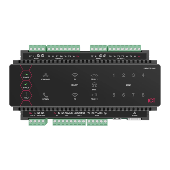
B+ B- NOCOM NC NOCOMNC T1i R1i T1oR1o 12VDC IN RS485 NETWORK BELL RELAY 1 RELAY 2 MODEM ETHERNET 12VDC Input Ethernet Interface RS-485 Input Panel Modem Interface Status Indicators Bell/Relay Outputs PRT-WX-DIN | Protege WX DIN Rail Integrated System Controller | Installation Manual... -
Page 55: Mechanical Layout
The mechanical layout shown below outlines the essential details needed to help ensure correct installation and mounting. All measurements are shown in millimeters. 156.80 Front 156.80 42.40 72.00 42.40 Back 139.18 PRT-WX-DIN | Protege WX DIN Rail Integrated System Controller | Installation Manual... -
Page 56: Technical Specifications
UL/ULC 0° to 49°C (32° to 120°F) : EU EN -10° to 55°C (14° to 131°F) Storage Temperature -10˚ to 85˚C (14˚ to 185˚F) Humidity 0%-93% non-condensing, indoor use only (relative humidity) PRT-WX-DIN | Protege WX DIN Rail Integrated System Controller | Installation Manual... -
Page 57: Current And Validation Example
If combining reader technologies, they must be connected on separate ports. The ICT implementation of OSDP conforms to a subset of the OSDP functionality. For specifications and reader configuration, refer to AN-254 Configuring OSDP Readers, available from the ICT website. -
Page 58: New Zealand And Australia
In contrast, sites where automated testing functions have been implemented may find that annual maintenance visits are adequate. PRT-WX-DIN | Protege WX DIN Rail Integrated System Controller | Installation Manual... -
Page 59: Recommended Routine Maintenance Procedures
Note: When the mains power is restored following an AC fail condition, the battery charge voltage may fluctuate between 10.0 - 13.8 VDC while the battery is recharging. PRT-WX-DIN | Protege WX DIN Rail Integrated System Controller | Installation Manual... - Page 60 Record and report any discrepancies. Special testing equipment and procedures may be required for smoke, heat, seismic glass-break and other detectors. PRT-WX-DIN | Protege WX DIN Rail Integrated System Controller | Installation Manual...
- Page 61 Record these in the maintenance sheets modifications and report. At the conclusion of Obtain client sign Obtain the signature of the client or the client's representative on each maintenance the maintenance record. visit PRT-WX-DIN | Protege WX DIN Rail Integrated System Controller | Installation Manual...
-
Page 62: European Standards
SP6 (LAN – Ethernet) and DP1 (LAN – Ethernet + PSTN) Tests EMC (operational) according to EN 55032:2015 Radiated disturbance EN 55032:2015 Power frequency Magnetic field immunity tests (EN 61000-4-8) PRT-WX-DIN | Protege WX DIN Rail Integrated System Controller | Installation Manual... -
Page 63: Uk Pd 6662:2017 And Bs 8243
Warning: Enclosures supplied by 3rd parties may not be EN50131-compliant, and should not be claimed as such. UK PD 6662:2017 and BS 8243 Protege systems conform to PD 6662:2017 and BS 8243 at the security grade and notification option applicable to the system. PRT-WX-DIN | Protege WX DIN Rail Integrated System Controller | Installation Manual... -
Page 64: Ul And Ulc Installation Requirements
(DAXW/C) central station automation system software and compatible receiving equipment. CID Receiver via Onboard Modem: Any UL and ULC listed receiver that uses the Contact ID protocol. ⦁ PRT-WX-DIN | Protege WX DIN Rail Integrated System Controller | Installation Manual... -
Page 65: Ul Operation Mode
Operator Reference Manual. The Poll Time must be programmed to 40 seconds. Refer to the Report IP | General section in the Operator Reference Manual. ⦁ Central Station Signal Receiver PRT-WX-DIN | Protege WX DIN Rail Integrated System Controller | Installation Manual... - Page 66 Network access policies should be set to restrict unauthorized network access and "spoofing" or "denial of service" attacks. ⦁ Ethernet Connections All ethernet network connections shall be installed within the same room as the equipment. ⦁ Encryption PRT-WX-DIN | Protege WX DIN Rail Integrated System Controller | Installation Manual...
- Page 67 Point Code as defined in the Serial Receiver settings Refer to the section Global Settings | Serial Receiver in the ArmorIP Version 3 Internet Monitoring Application User Manual. PRT-WX-DIN | Protege WX DIN Rail Integrated System Controller | Installation Manual...
-
Page 68: Can/Ulc-S319
The ArmorIP Receiver supports up to 10000 simultaneous connections. Refer to the section Internet Connections Requirements in the ArmorIP Receiver Installation Manual for further details. ⦁ Number of attempts PRT-WX-DIN | Protege WX DIN Rail Integrated System Controller | Installation Manual... - Page 69 Any available dry relay contact on the Protege controller or output expander may be used for the FACP system, provided the selected output is programmed as the Report OK output. PRT-WX-DIN | Protege WX DIN Rail Integrated System Controller | Installation Manual...
- Page 70 TROUxLE Programmable vOM4ST*TUS4r4Fx Output u4The4*v4F*IL4output4on4the4Power4Supply4MUST4be4programmed4to4follow4the4*v4Trouble4Input4as4followsD *v4F*IL4,4OPEN4on4fail u4Fire4areas4shall4be4separated4from4burglar4areas4through4area4partitioningi u4Fire4Inputs4ZoqZm4shall4be4used4exclusively4for4fire4monitoring4and4cannot4be4programmed4to4activate4the4bell4output u4Fire4Input4Z:4NiO4Push4xutton4to4be4used4as4monitoring4reset4switchi Typical4Input4vircuits EOL Resitor Input Configuration Niv4Input4vontact Value4o Value4l Monitored4Status Tamper Value4l Value4o Opene4vlosee4Tampere4Short Opene4vlosee4Tampere4Short Opene4vlosee4Tampere4Short Opene4vlosee4Tampere4Short Opene4vlosee4Tampere4Short Opene4vlosee4Tampere4Short 4uEOL4resistor4must4be4installed4at4the4Fire4*larm4vontrol4Panel4Outputi PRT-WX-DIN | Protege WX DIN Rail Integrated System Controller | Installation Manual...
- Page 71 All fire area inputs must be placed into an area and this area must be armed. Please refer to the section Inputs | Areas and Input Types in the Operator Reference Manual. ⦁ COM Status PRT-WX-DIN | Protege WX DIN Rail Integrated System Controller | Installation Manual...
-
Page 72: Ul Compliance Requirements
The Contact ID Reporting Service must be enabled and the Service Mode must be configured to start with the operating system. Refer to the section Contact ID in the Operator Reference Manual PRT-WX-DIN | Protege WX DIN Rail Integrated System Controller | Installation Manual... -
Page 73: Ul294
If fire resistance is required for door assembly, portal locking device(s) must be evaluated to UL10B or ⦁ UL10C. Must be installed with UL 1034 listed electronic locks for UL installations. ⦁ PRT-WX-DIN | Protege WX DIN Rail Integrated System Controller | Installation Manual... - Page 74 If a flexible cord is used to connect to line voltage, strain relief must be provided for the cord inside the ⦁ enclosure or at the knockout. ⦁ The power supply is not intended to be mounted on the exterior of vault, safe, or stockroom. PRT-WX-DIN | Protege WX DIN Rail Integrated System Controller | Installation Manual...
-
Page 75: Fcc Compliance Statements
AAAEQ##TXXXX. The digits represented by ## are the REN without a decimal point (e.g., 03 is a REN of 0.3). For earlier products, the REN is separately shown on the label. PRT-WX-DIN | Protege WX DIN Rail Integrated System Controller | Installation Manual... - Page 76 Network Service Provider's Computer RJ-31X Facilities Jack Unused Alarm Dialing RJ-11 Jack Equipment Telephone Line Telephone Network Unused Demarcation Fax Machine RJ-11 Jack Telephone Point Answering System Telephone PRT-WX-DIN | Protege WX DIN Rail Integrated System Controller | Installation Manual...
-
Page 77: Industry Canada Statement
à la seule condition que la somme d’indices d’équivalence de la sonnerie de tous les dispositifs n’excède pas 5. Controller REGISTRATION NUMBER IC: 10012A-PRTCTRLDIN Controller NUMÉRO D'ENREGISTREMENT IC: 10012A-PRTCTRLDIN PRT-WX-DIN | Protege WX DIN Rail Integrated System Controller | Installation Manual... -
Page 78: Disclaimer And Warranty
Integrated Control Technology Ltd nor its employees shall be liable under any circumstances to any party in respect of decisions or actions they may make as a result of using this information. In accordance with the ICT policy of enhanced development, design and specifications are subject to change without notice. - Page 79 Disclaimer: Whilst every effort has been made to ensure accuracy in the representation of this product, neither Integrated Control Technology Ltd nor its employees shall be liable under any circumstances to any party in respect of decisions or actions they may make as a result of using this information. In accordance with the ICT policy of enhanced development, design and specifications are subject to change without notice.
Need help?
Do you have a question about the PRT-WX-DIN and is the answer not in the manual?
Questions and answers