Table of Contents
Advertisement
Advertisement
Table of Contents

Related Manuals for Genicom LA36N


Summary of Contents for Genicom LA36N
-
Page 1: Installation Guide
GENICOM Matrix Printer LA36 Installation Guide GENICOM Corporation... - Page 2 GENICOM Corporation. © GENICOM Corporation 2000. All rights reserved. The following are trademarks of GENICOM Corporation: GENICOM Matrix Printer LA36N, GENICOM Matrix Printer LA36W, and the GENICOM logo. Centronics is a trademark of Centronics Data Computer Corporation. IBM PC, IBM Proprinter X24E and IBM Proprinter XL24E are trademarks of International Business Machines Corporation.
-
Page 3: Fcc Compliance Statement
FCC Compliance Statement This device complies with Part 15 of the FCC Rules. Operation is subject to the following two conditions: (1) This device may not cause harmful interference, and (2) This device must accept any interference received, including interference that may cause undesired operation. - Page 4 Notes The use of a nonshielded parallel interface cable with the referenced device is prohibited. The length of the parallel interface cable must be 3 meters (10 feet) or less. The length of the serial interface cable must be 600 meters (1970 feet) or less. The length of the power cord must be 3 meters (10 feet) or less.
-
Page 5: Table Of Contents
Your new LA36 printer is easy to install and set up. Just follow the step-by-step procedures contained in this part to set up the printer and starting printing right away. If this is your first printer, you should read the entire part before attempting to use the printer. -
Page 6: Selecting A Good Location
• Ensure easy access to the front and rear of the printer by leaving about eight inches (20 cm) of space around the printer. Do not block the air vents 1 on the left side of the printer. Power Supply •... -
Page 7: Step 2 - Unpacking The Printer
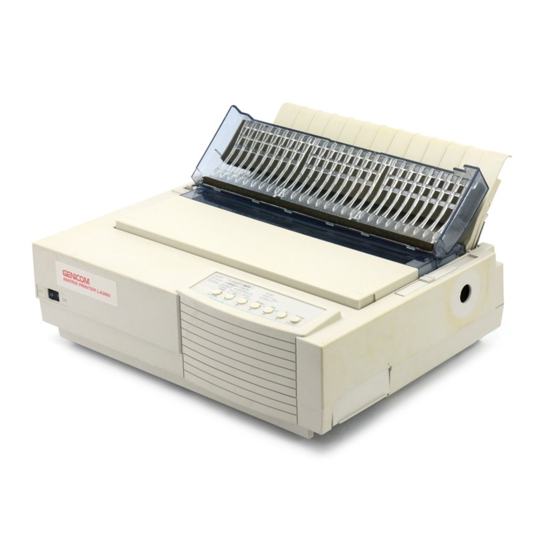
Opening the Carton Unpack the printer as follows: 1. Open the carton and remove the printer and its components. Make sure that you have all of the items shown below: GENICOM Matrix Printer LA36N 2 - Black ribbon cartridge 3 - Cut sheet stand 4 - Platen knob - not mounted when shipped. - Page 8 5. Open the front cover 2 and remove the print head shipping restraint (cardboard) 3. 6. At the back of the printer, remove the two tractor unit securing tapes (adhesive tapes) 4 and the bail unit shipping restraints (two adhesive tapes 5 and a cardboard 6).
-
Page 9: Step 3 - Assembling The Printer
The platen knob allows you to manually feed the paper. To mount the platen knob: 1. Insert the platen knob 1 on the platen axle 2 on the right side of the printer. 2. Push the platen knob 1 until it stops against the axle 2. -
Page 10: Installing The Cut Sheet Stand
1. Tilt the acoustic cover 1 towards the front of the printer 2. Locate the two grooved notches 2 on each side of the top of the printer, behind the top cover. Note that each notch has a front groove and a rear groove. - Page 11 3. Locate the two mounting pins 3 on each side of the cut sheet stand 4. 4. Hold the cut sheet stand vertically over the top of the printer. Slide the mounting pins 3 into the long, front grooves 2 so that the cut sheet stand is mounted on the printer. This is the cut sheet stand’s up position, used for printing single sheets.
-
Page 12: Installing The Ribbon Cartridge
Installing the Ribbon Cartridge The basic printer uses a black ribbon cartridge. Note: If you have the color kit option, see Appendix A, “Supplies and Options,” to see how to install the color ribbon cartridge. Preparing the Printer To install the ribbon cartridge: 1. - Page 13 3. Move the paper thickness lever 4 to the position D. Positioning the Paper Thickness Lever Preparing the Black Ribbon Cartridge 1. Remove the ribbon cartridge from its plastic packet. 1 - Ribbon release tabs 2 - Ribbon feed mechanism 3 - Ribbon 4 - Ribbon feed knob 5 - Ribbon cartridge release lever...
- Page 14 2. Push both gray ribbon release tabs 1 so that they snap into the cartridge and the ribbon feed mechanism 2 moves to the 3. Turn the ribbon feed knob 4 clockwise (according to the engraved arrow) to be sure that the ribbon 3 feeds properly.
- Page 15 Inserting the Ribbon Cartridge 1. Place the mounting pins 1 of the ribbon cartridge on the support brackets 2 of the print head carriage. 2. Insert ribbon 3 so that it falls between the metallic nose 4 of the print head and the plastic print guide 5 .
-
Page 16: Step 4 - Connecting The Power Cord
To plug in the power cord: 1. Plug one end of the power cord into the power connector on the rear of the printer. 2. Plug the other end of the power cord into the power outlet. - Page 17 PPX24 its home position, and the Soft Ctrl. Caution: In this step, there is no paper loaded, the printer beeps and the lights. The indicator will light depending on the setting of the paper Ready select lever located on the top left of the printer.
-
Page 18: Testing The Printer
At this point, you are now ready to load paper and run the printing test. The printing test is a built-in function for checking printer performance and print quality before you connect the printer to the computer. This section describes the test procedure using single sheets. - Page 19 3. Open the acoustic cover and move the left paper guide 3 all the way to the right. 4. Adjust the right paper guide 4 to the width of the paper without actually inserting the sheet inside the printer. 5. Slide the sheet along the cut sheet stand until its bottom edge touches flat on the platen.
- Page 20 If the printing test stops because of paper out, insert a new sheet of paper into the cut sheet stand. The printing test restarts automatically. If the print quality remains poor, turn off the printer and contact your dealer for assistance.
- Page 21 Connecting the Printer to a DIGITAL Environment In a DIGITAL environment, you only need to connect the printer to your host system and to check if the serial communication is properly set. Connecting the Printer to the Computer, Server or Terminal To connect the printer: 1.
- Page 22 2. While pushing the top of the shutter 1 on the right side of the printer with your thumb, lift the bottom of the shutter with your fingers until the shutter stays open, allowing access to the connectors. 3. Insert the serial cable connector 2 into the socket 3, until its stopper clicks into place.
-
Page 23: A Test Page From Your Host System
Connecting the Printer to a PC Environment In a PC environment, you need to connect the printer to your PC using a parallel interface cable and install the Windows printer driver located on the User Documentation and Software CD ROM. - Page 24 To connect the printer: 1. Turn off the printer. 2. While pushing the top of the shutter 1 on the right side of the printer with your thumb, lift the bottom of the shutter with your fingers until the shutter stays open, allowing access to the connectors.
- Page 25 6. Push down the shutter 1 until it clicks locked. Checking the Protocol A protocol is a set of commands used by your software to communicate with the printer. There are many different protocols available for printers. Each protocol has unique features and capabilities.
- Page 26 2. Insert a sheet in the printer and press the 3. Open a file from a basic application, such as Write for example. 4. Ensure that the Printer Driver is selected and that the settings match your paper size or other specific parameters accompanying your file: –...
- Page 27 Printing a Test Page under Windows 95/98 During installation under Windows 95/98, select the option related to the printing of a print test page in order to check the correct installation of your printer driver. Printing a Test Page under NT 4.0 During installation under NT 4.0, select the option related to the printing of a print test page...
- Page 28 1-24...
-
Page 29: Chapter 2 Maintenance
This section explains how to clean and vacuum the printer and how to clean the platen and paper bail rollers. It is easier to clean the printer when the front cover, the cut sheet stand, and back cover are removed. - Page 30 Warning: Do not use solvents, kerosene, or abrasive cleaning materials that may damage the printer. 4. Open the front cover of the printer and remove the ribbon cartridge. Using a soft vacuum brush, gently vacuum the platen, the print head carriage and shaft, and surrounding areas.
-
Page 31: Replacing The Ribbon Cartridge
To clean the platen and the bail rollers: 1. Apply a small amount of alcohol or water to a soft cloth. Avoid spilling alcohol or water inside the printer. 2. Place the cloth against the platen and manually rotate the platen knob. - Page 32 (from left to right). Warning: The print head may be hot if you have been printing recently. 3. Move the paper thickness lever 1 located on the top right of the printer to position D.
- Page 33 Maintenance 4. To remove the ribbon cartridge, press the ribbon release levers 2 located on the sides of the cartridge and carefully lift the cartridge out of the printer. Removing the Ribbon Cartridge 5. Remove the new ribbon cartridge from its package.
-
Page 34: Replacing The Print Head
Warning: The print head may be hot if you have been printing recently. To remove the print head: 1. Turn off the printer. 2. Open the front cover and remove the ribbon cartridge. 3. Pull the right end of the head lock wire 1 forward to release it from the hook at the right of the print head carriage. -
Page 35: Troubleshooting
• Printer failure Print Quality Problems and Solutions Poor print quality or other printing problems are often caused by incorrect printer set-up or incorrect software settings. A gradual decrease in print quality usually indicates a worn ribbon. The following table identifies common print quality problems and suggests solutions. - Page 36 If you are using a DEC-423 serial interface, make sure that the serial settings required by your software or computer are the same as the settings on the printer. See the section, “Changing Install Options,” in Chapter 4 of the User Manual.
- Page 37 Solution The top margin is the sum of the printer’s top-of-form setting, the software-specified top margin, and the printer’s TOP-MRGN setting. Proceed as follows: • Make sure that the top-of-form setting is correct.
-
Page 38: Paper Handling Problems And Solutions
Paper jams while printing. Solution Make sure that the paper select lever located on the top left of the printer is set correctly. Move the lever backward for continuous forms or forward for single sheets. Make sure that the paper covers the paper-out sensor, i.e., the left paper edge is within 52 mm for single... -
Page 39: Operating Problems And Solutions
See the section, “Using Continuous Forms,” in Chapter 2 of the User Manual. Solution Make sure that the “I” on the printer power switch is depressed. Make sure that the power cord is securely connected to both the printer and the outlet. Make sure that the power outlet is functional. -
Page 40: Diagnostic Functions
• +34 V overvoltage error No error condition is displayed if any of these errors occurs. Turn the printer off and back on; then rerun the same job to check if the error was transient. If the error recurs, contact your dealer. -
Page 41: Checking Vertical Alignment
Make sure that continuous forms paper or single sheet paper is loaded in the printer. If possible, use forms at least 216 mm (8.5 inches) wide for LA36N or 356 mm (14 inches) wide for LA36W to avoid printing on the platen. Then proceed as follows: 1. - Page 42 Press the button to save the new vertical alignment settings and exit the vertical Exit/Save alignment function. Note: To exit the vertical alignment function without saving changes, turn the printer off. button to switch Letter quality to Correspondence and Vertical Alignment...
-
Page 43: Appendix A Supplies And Options
This appendix lists the accessories and options available for the printer. Contact your dealer for information on ordering any of these items. Supplies Supplies Ribbon cartridges Black ribbon Color ribbon Print head Options Option Color kit Parallel interface cable Serial interface cable... -
Page 44: Installing Options
This section contains an introductory outline of the options available. Installing the Color Kit You can turn your monochrome printer into a color printer by installing a color kit on the print head carriage. The ribbon shift unit (shown below) of the color kit vertically swings the color ribbon cartridge to position one of the four colors of ribbon in front of the print head. -
Page 45: Appendix B Technical Support
• Your Authorized Service Provider Your Printer Vendor Your local vendor from whom you purchased this printer may be best equipped to help you. Your vendor has specially trained service technicians available to answer questions and the equipment to analyze your printer problems. - Page 46 Technical Support is available world-wide. Please refer to your Printer Service and Support Information Guide available in the SERVICE Folder of the CD-ROM that accompanied your printer for the appropriate phone number in your area. When calling for assistance, please have the following information available: •...
-
Page 47: Appendix C Software And Documentation Cd-Rom
Software and Documentation CD-ROM The LA36N/LA36W Software and Documentation CD-ROM contains several software packages and online documentation designed to help you take advantage of all of the features of your printer. You may find additional LA36 information and updates to the contents of this CD-ROM on the internet: http://www.genicom.com.
Need help?
Do you have a question about the LA36N and is the answer not in the manual?
Questions and answers