
Related Manuals for Moxa Technologies ToughNet TN-4500A Series


Summary of Contents for Moxa Technologies ToughNet TN-4500A Series
- Page 1 TN-4500A Series Quick Installation Guide Moxa ToughNet Switch Version 4.0, May 2022 Technical Support Contact Information www.moxa.com/support 2022 Moxa Inc. All rights reserved. P/N: 1802045000013 *1802045000013*...
-
Page 2: Package Checklist
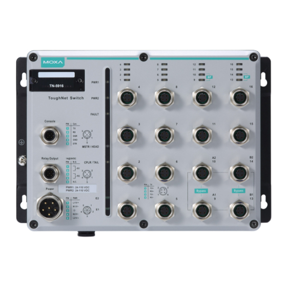
Overview The ToughNet TN-4500A Series M12 managed Ethernet switches are designed for industrial applications in harsh environments. The TN Series switches use M12 connectors to ensure tight, robust connections, and guarantee reliable operation against environmental disturbances, such as vibration and shock. The wide 24 to 110 VDC dual power inputs increases the reliability of your communications. - Page 3 Features Anti-Vibration Circular Connectors for Robust Links • M12 D-coded 4-pin female connectors for 10/100BaseT(X) Fast Ethernet ports • M12 X-coded 8-pin female connectors for 10/100/1000BaseT(X) Gigabit Ethernet ports • M12 A-coded 5-pin male connectors for console and relay outputs •...
-
Page 4: Recommended Optional Accessories
Recommended Optional Accessories • CBL-M23(FF6P)/OPEN-BK-100-IP67: 1-meter M23 to 6-pin power cable with IP67-rated female 6-pin M23 connector • CBL-M12D(MM4P)/RJ45-100 IP67: 1-meter M12-to-RJ45 Cat-5E UTP Ethernet cable with IP67-rated male 4-pin M12 D-coded connector • CBL-M12(FF5P)/OPEN-100 IP67: 1-meter M12-to-5-pin power cable with IP67-rated female 5-pin M12 A-coded connector •... - Page 5 TN-4512A Series Panel Layouts 1. Model name 2. Screw holes for panel mounting kit 3. Console port 4. Grounding screw 5. Relay output port 6. Power input port (M23 6-pin shielded male connector) 7. PWR1 LED: for power input 1 8.
- Page 6 TN-4516A non-PoE Series Panel Layouts 1. Model name 2. Screw holes for wall mounting kit 3. Console port 4. Grounding screw 5. Relay output port 6. Power input port (M23 6-pin shielded male connector) 7. PWR1 LED: for power input 1 8.
- Page 7 TN-4516A PoE Series Panel Layouts 1. Model name 2. Screw holes for wall mounting kit 3. Console port 4. Grounding screw 5. Relay output port 6. Power input port (M23 6-pin shielded male connector) 7. PWR1 LED: for power input 1 8.
- Page 8 TN-4516A Fiber Series Panel Layouts 1. Model name 2. Screw holes for wall mounting kit 3. Console port 4. Grounding screw 5. Relay output port 6. Power input port (M23 6-pin shielded male connector) 7. PWR1 LED: for power input 1 8.
- Page 9 TN-4520A Series Panel Layouts 1. Model name 2. Screw holes for wall mounting kit 3. Console port 4. Grounding screw 5. Relay output port 6. Power input port (M23 6-pin shielded male connector) 7. PWR1 LED: for power input 1 8.
- Page 10 TN-4524A Series Panel Layouts 1. Model name 2. Screw holes for wall mounting kit 3. Console port 4. Grounding screw 5. Relay output port 6. Power input port (M23 6-pin shielded male connector) 7. PWR1 LED: for power input 1 8.
- Page 11 TN-4528A PoE Series Panel Layouts 1. Model name 2. Screw holes for wall mounting kit 3. Console port 4. Grounding screw 5. Relay output port 6. Power input port (M23 6-pin shielded male connector) 7. PWR1 LED: for power input 1 8.
- Page 12 TN-4528A Fiber Series Panel Layouts 1. Model name 2. Screw holes for wall mounting kit 3. Console port 4. Grounding screw 5. Relay output port 6. Power input port (M23 6-pin shielded male connector) 7. PWR1 LED: for power input 1 8.
-
Page 13: Mounting Dimensions (Unit = Mm)
Mounting Dimensions (unit = mm) TN-4512A Series - 13 -... - Page 14 TN-4516A non-PoE Series TN-4516A PoE Series - 14 -...
- Page 15 TN-4516A Fiber (ODC) Series TN-4520A Series - 15 -...
- Page 16 TN-4524A Series TN-4528A PoE Series - 16 -...
- Page 17 TN-4528A Fiber (ODC) Series - 17 -...
-
Page 18: Wall Mounting
Wall Mounting STEP 1: Mounting the TN-4500A to a wall requires 4 screws. Use the ToughNet switch as a guide to mark the correct positions of the 4 screws. STEP 2: Use the 4 screws in the wall-mounting kit. If you would like to use your own screws, make sure the screw head is between 6.0 mm and 7.0 mm in diameter and... -
Page 19: Wiring Requirements
Wiring Requirements WARNING Turn the power off before disconnecting modules or wires. The correct power supply voltage is listed on the product label. Check the voltage of your power source to make sure you are using the correct voltage. Do NOT use a voltage greater than what is specified on the product label. -
Page 20: Grounding The Toughnet Switch
Connecting the Power Supplies The ToughNet TN-4500A Series switches support dual power inputs— power input 1 and power input 2. The M23 6-pin male connector on the TN-4500A Series switches' front panel is used for connecting dual power inputs. -
Page 21: Connecting The Relay Outputs
Pinouts for the power input port on the TN-4500A Series (M23) Description Usage Connect “PWR1 Live / DC +” to the positive (+) PWR1 / DC + terminal when using a DC power source. Connect “PWR1 Neutral / DC -” to the negative PWR1 / DC - (-) terminal when using a DC power source. -
Page 22: Connecting The Data Lines
Pinouts for the relay output port on the TN-4500A Series N.C.: Not connected FAULT: The two sets of relay contacts of the M12 A-coded 5-pin male connector are used to detect user-configured events. The two wires attached to the fault contacts form an open circuit when a user-configured event is triggered. - Page 23 Pinouts for the 1000Base-X (including 1000Base-LSX) Q-ODC® Gigabit Fiber port Mating Sequence Rotate to find keying Unmated – push Mated – connector Pull coupling ring to position connector to mate snaps in and is fully unmate strain relieved Gigabit Ethernet Q-ODC Multi-mode Fiber Cable Type 50/125...
- Page 24 M12 (4-pin, M) to RJ45 (8-pin) Cross-Over Cable Wiring M12 (4-pin, M) to RJ45 (8-pin) Straight-Trough Cable Wiring M12 (8-pin, M) to M12 (8-pin, M) Cross-Over Cable Wiring - 24 -...
- Page 25 M12 (8-pin, M) to M12 (8-pin, M) Straight-Trough Cable Wiring M12 (8-pin, M) to RJ45 (8-pin) Cross-Over Cable Wiring M12 (8-pin, M) to RJ45 (8-pin) Straight-Trough Cable Wiring - 25 -...
- Page 26 ATTENTION The protective cover must be fixed properly to ensure IP42 protection. Use a torque wrench set to a torque of 4 kgf-m when tightening the screws. Note that applying a larger torque may damage the plastic protective cover. Bypass Relay Function The TN-4516A-4GTXBP, TN-4516A-12PoE-2GPoE-2GTXBP, and TN- 4528A-16PoE-2GPoE-2GTXBP models have 2 to 4 Gigabit ports equipped with bypass relay functionality.
-
Page 27: Led Indicators
LED Indicators Several LED indicators are located on the ToughNet switch’s front panel. The function of each LED is described in the table below. Color State Description System LEDs Power is being supplied to power input PWR1. PWR1 AMBER Power is not being supplied to power input PWR1 Power is being supplied to power input PWR2. - Page 28 Color State Description The port’s 1000 Mbps link is active. GREEN Blinking Data is being transmitted at 1000 Mbps. The port’s 1000 Mbps link is inactive. G1/G2 The port’s 1000 Mbps link is active. (1000M, Blinking Data is being transmitted at 1000 Mbps. GREEN for fiber The port’s 1000 Mbps link is inactive.
Need help?
Do you have a question about the ToughNet TN-4500A Series and is the answer not in the manual?
Questions and answers