MIMAKI Tiger600-1800TS Operation Manual
Hide thumbs
Also See for Tiger600-1800TS:
- Maintenance manual (28 pages) ,
- Care and maintenance (40 pages)

Related Manuals for MIMAKI Tiger600-1800TS


Summary of Contents for MIMAKI Tiger600-1800TS
- Page 1 You can also download the latest manual from official website. MIMAKI ENGINEERING CO., LTD. https://mimaki.com/ D203673-11 Original instructions...
-
Page 2: Table Of Contents
TABLE OF CONTENTS Introduction .................. 5 To Ensure Safe Use ............... 6 Symbols .................... 6 Usage Precautions ................ 7 Prohibited Dangerous Actions ............ 11 Usage Restrictions................ 13 Usage Restrictions................ 13 Operator Restrictions................ 13 Area Restrictions ................ 13 Connecting the Power .............. 15 Tiger600 Wiring Configuration ............ - Page 3 Stopping Printing ................ 95 Skipping the wait until heater temperature is reached...... 95 Printing Using Nozzle Recovery ............ 96 Chapter 3 Settings (MPC) 3.1 Mimaki Printer Controller ............ 100 Screen structure ................ 100 3.2 Print menu ................ 104 3.3 Maintenance Menu ............... 105 Registering abnormal nozzle with the nozzle check tool ....
- Page 4 4.3 Performing Maintenance............ 132 Ink Maintenance ................ 132 Wiper Cleaning ................. 132 Carriage Underside Cleaning ............ 134 Wiper Unit Cleaning................ 135 Flushing Box Cleaning.............. 136 Moisture Tray Cleaning.............. 136 Exterior Cleaning (e.g., cover, Y-bar, ) .......... 137 Jam Sensor Detecting Plate Cleaning .......... 138 Platen Cleaning ................
-
Page 5: Introduction
Adobe, the Adobe logo, Acrobat, Illustrator, Photoshop, and PostScript are the trademarks or registered trademarks of Adobe Incorporated in the United States and other countries. TxLink is a trademark or a registered trademark of Mimaki Engineering Co. Ltd. in Japan and other countries. -
Page 6: To Ensure Safe Use
To Ensure Safe Use To Ensure Safe Use Symbols In this manual, the symbols indicate and explain precautions. Make sure you fully understand the meaning of each symbol and use the machine safely and correctly. Explanation Warning Indicates a potential hazard that may result in death or serious injury if handled improperly or if instructions are disregarded. -
Page 7: Usage Precautions
To Ensure Safe Use Usage Precautions l In the event of abnormal conditions • In the event of abnormal conditions such as smoke or unusual odor, turn off the main power immediately and turn off the breaker. Continuing to use the machine under these conditions may result in failure, electric shock, or fire. - Page 8 To Ensure Safe Use l Power supply precautions • Do not damage or modify the power cable. Do not place heavy objects on, heat or stretch it. Doing so may damage the cable, leading to electric shock or fire. • Do not use the power cable if it is damaged or broken or if the core wire is exposed. Otherwise there is a risk of failure, electric shock, or fire.
- Page 9 To Ensure Safe Use • When used in a low-temperature environment, the vacuum unit may generate a high-pitched noise. The high-pitched sound does not indicate a failure. l Do not stand or sit on the machine. • Never stand or sit on the platen. Disregarding this precaution may impair the precision of the platen surface and affect print quality.
- Page 10 To Ensure Safe Use l About the touch panel • Do not press, rub, or push the touch panel with excessive force. • Do not tap the touch panel with a ball-point pen or other hard metal object. • Do not touch the black outer frame of the screen. •...
-
Page 11: Prohibited Dangerous Actions
To Ensure Safe Use Prohibited Dangerous Actions Never perform any of the following dangerous actions while the power is turned on. Disregarding these precautions may result in serious injury (crushing or severing) if the carriage moves, for example during periodic maintenance. l Keep face, hands, and body away from carriage •... - Page 12 To Ensure Safe Use l Keep face, hands, body, and other objects away from cableveyor • Keep your face, hands, and body away from the Y cableveyor, and do not place objects on top of it. l Keep face, hands, and body away from underneath platen during operation •...
-
Page 13: Usage Restrictions
Usage Restrictions Usage Restrictions Usage Restrictions • The machine includes fast-moving and high temperature parts, which present extreme hazards. The machine must be used only by persons that are fully aware of these potential dangers. Operator Restrictions • The machine must be operated only by persons that have received our safety training or who have been trained by such trained personnel. - Page 14 Usage Restrictions • If a safety fence is used to restrict the area, this should comply with the EN ISO 13857 standard. • If the machine is installed in a dedicated room, locks and safety Interlocks should be provided on the doors to the room, and ultimately a risk assessment should be conducted for the installation before use.
-
Page 15: Connecting The Power
Connecting the Power Connecting the Power The printer requires a large power supply and must be powered directly from the switchboard. Customers must complete any electrical work before the printer is carried in. • Always connect the machine to a switchboard with grounded polarity. Otherwise there is a risk of failure, electric shock, or fire. - Page 16 Connecting the Power l Wire preparation Strip the power cable sheath as shown in the diagram below. Black 1: L1 Black 2: L2 Black 3: L3 Black 4: N Green/yellow: FG *1: Please prepare the wire according to the particular crimp terminal specifications. Attach the allowable types of crimp terminals to the L1, L2, L3, N, and FG wires.
- Page 17 Connecting the Power • Be sure to observe the following three points. Failure to observe the following three points may result in fire, smoke generation, or electric shock. (1) Only use power cables and crimp terminals that satisfy the specifications. (2) Be sure to attach a ring crimp terminal to the end of the power cable.
- Page 18 Connecting the Power Secure the L1, L2, L3, and N wires to the terminal block, and secure the FG wire to the screw hole next to the protective ground name plate. • Tighten the terminal block screws to a torque of 2.2 to 2.8 Nm. Terminal block Clamp Clamp...
-
Page 19: Ink And Other Liquid Handling Precautions
Thoroughly read them and make sure you understand the contents. • Be sure to read the safety data sheet (SDS) before use. https://mimaki.com/supply/sds/ • Pay close attention to ventilation and be sure to wear safety glasses, gloves, and a mask when handling ink, maintenance liquid, waste ink, or other solutions used with the machine. -
Page 20: Ink Specifications
Ink and Other Liquid Handling Precautions Ink Specifications Item Details Type MLSb510 Color Yellow (Y) Magenta (M) Blue (B) Black (K) Form Ink tank or pack-in-box Ink capacity Expiration date As indicated on the Ink tank. However, ink should be consumed within three months after opening, even if before the expiration date. -
Page 21: Installation Precautions
Installation Precautions Installation Precautions • Do not install the machine in locations where naked flames are used. • Do not place plant pots, cups, containers of cosmetics, chemicals, or water, or small metal objects on top of the machine. There is a risk of failure, electric shock, or fire if liquids or other items fall inside the machine. -
Page 22: Installation Space
Installation Precautions Installation Space Provide the following space around the machine to allow safe and proper replacement of ink and media: Item Tiger600-1800TS At least 8,300 mm (5,300 mm) Width At least 5,800 mm (2,800 mm) Depth (1,900 mm) Height... -
Page 23: Adjuster Feet
Installation Precautions Adjuster Feet Do not attempt to adjust the adjuster feet yourself. Doing so may prevent the machine from operating correctly. If you have any queries, contact your local distributor, our sales office, or service center. [Top view] Large adjuster feet Small adjuster feet When Relocating This Machine Contact your local dealer or our service office. -
Page 24: Emergency Stop Switches And Light Curtain
Emergency Stop Switches and Light Curtain Emergency Stop Switches and Light Curtain The machine is equipped with emergency stop switches and a light curtain to ensure safety during use. The light curtain stops the machine when a person or object is detected. •... -
Page 25: Warning Labels
Warning labels Warning labels Make sure you fully understand the details indicated on the various warning labels. If any of the warning labels becomes dirty and illegible or peel off, contact your local dealer or our service office to request new warning labels. - Page 26 Warning labels Order code Label Details M903239 Indicates hot parts. M903281 Note when connecting the power supply cable. M903330 Wear safety glasses and gloves while working. M905624 Caution regarding current leakage. M906115 Caution regarding moving parts. M906222 Caution overhead. M907764 Do not climb on top CAUTION ATTENTION...
- Page 27 Warning labels Order code Label Details M912054 Caution regarding entrapment. M918531 Caution when lifting heavy objects.
- Page 28 Warning labels...
-
Page 29: Chapter 1 Before Use
Chapter 1 Before Use This chapter This chapter describes information essential before use, such as part names. Items to be Prepared by the Customer ...30 System Configuration ........3 8 Connecting to a Local Network ....3 9 Part Names and Functions ......31 Front/Rear .......... -
Page 30: Items To Be Prepared By The Customer
Chapter 1 Before Use 1.1 Items to be Prepared by the Customer The following items should be prepared by the customer before installing the machine. l Equipment and consumable items Provided by user Control PC Printer unit Scanner Item Remarks RIP PC Reference: "Recommended RIP PC requirements"(P. -
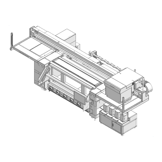
Page 31: Part Names And Functions
Chapter 1 Before Use 1.2 Part Names and Functions Front/Rear [Front] MAINT PRINT [Rear side] Tension JOG CCW CW... - Page 32 Supplies ink to the print head from the Ink tank. "Ink Supply Unit"(P. 34) 11 Touch panel The touch panel is used to control the machine. "Mimaki Printer Controller"(P. 100) • How to operate the touch panel – Tap: Select a function.
- Page 33 Chapter 1 Before Use Name Overview 21 Rotation direction Used to change the rotation direction of the take-up unit and feeding unit switch respectively. CCW/CW...
-
Page 34: Ink Supply Unit
Chapter 1 Before Use Ink Supply Unit Name Overview Ink tank Mount the Ink tank. "Replacing the Ink Tank"(P. 52) Cap cover Lift up the lever to remove the Ink tank. Winding unit Name Overview Take-up Unit Rolls up the printed roll media. "Load the media."(P. -
Page 35: Station
Chapter 1 Before Use Station The station includes a moisture tray for preventing the print head nozzle surface from drying out, and a wiper required for print head maintenance. Platen Print area. The platen secures the media under vacuum pressure. Light Curtain The light curtain is used to stop the machine when a person or object is detected. -
Page 36: Signal Tower Light
Chapter 1 Before Use Signal tower light The signal tower light allows the machine status to be confirmed from the color of the illuminated lights. Color Status Overview Illuminated Error level 2 or 3 occurrence Printing is not possible due to system failure. The printer is operating normally. -
Page 37: Maintenance Switch
Chapter 1 Before Use Maintenance Switch Switch for selecting maintenance mode (MAINT) or print mode (PRINT). Be sure to switch to maintenance mode before carrying out maintenance work. The light curtain is disabled when in maintenance mode. "Light Curtain"(P. 35) [Maintenance mode selected] [Print mode selected] MAINT PRINT... -
Page 38: System Configuration
Use RIP software to prepare jobs (RIP data) from print data created in applications such as Illustrator or Photoshop. Jobs prepared this way are printed using the MPC (Mimaki Printer Controller) application installed on the machine (control PC). "Settings (MPC)"(P. 99) -
Page 39: Connecting To A Local Network
Chapter 1 Before Use Connecting to a Local Network Connect the machine (control PC) and RIP PC via a local network or direct LAN cable to enable jobs (RIP data) to be easily imported. Insert the LAN cable until it clicks into place. l Machine (control PC) and RIP PC configuration The machine can be connected using one of the following two methods: •... - Page 40 Chapter 1 Before Use • If the indicators are not illuminated, insert the LAN cable until it clicks into place. [LINK/ACT] [SPEED] Status Overview SPEED Green Linked via 10GBASE-T Yellow Linked over a connection other than 10GBASE-T LINK/ACT Flashing green Data is being sent and received.
-
Page 41: Preparing The Rip Pc
The customer should provide a RIP PC and network devices that meet the recommended requirements. • TxLink cannot be installed on the Tiger600-1800TS control PC. The user must provide a separate PC for use with the RIP software. An Internet connection is also required in order to obtain the RasterLink license. - Page 42 Chapter 1 Before Use Select [Network & Internet]. Under the "Change your network settings" section, select [Sharing options]. Select [Private], [Guest or Public], or [Domain]. • The selection items may vary depending on the network configuration. Contact your network administrator.
- Page 43 Chapter 1 Before Use Select [Turn on network discovery] and click [Save changes]. Restart the RIP PC. Setting up an Ethernet connection On the RIP PC, open the Windows start menu and click [Settings]. Select [Network & Internet].
- Page 44 Chapter 1 Before Use Select [Change adapter options]. Right-click [Ethernet], and then select [Properties]. • If there are multiple [Ethernet] icons, select the properties for the port you wish to use. • The names may vary depending on the PC. On the Networking tab, select the [Internet Protocol Version 4 (TCP/IPv4)] item, then click [Properties].
-
Page 45: Installing Rip Software
• Check whether two folders, [HotFolder] and [SharedJob], are displayed. If they are displayed, configuration is complete. Installing RIP Software The explanation here applies to the MIMAKI RIP software (TxLink). • If using TxLink, refer to the TxLink operating manual. -
Page 46: Setting Up Rip Software
• The following icon appears on the PC desktop once the software has been installed. Setting Up RIP Software The explanation here applies to MIMAKI RIP software (TxLink). This section describes the procedure for registering the Tiger600 Series printer configuration. - Page 47 Chapter 1 Before Use Create a print client. (1) Click the [+] button. (2) Select the desired printer driver, then click [OK]. • Open the Mimaki Tiger600-1800 folder. (3) Select a port.
- Page 48 Chapter 1 Before Use • If the port is not listed in the combo box, follow these steps to create it. (1) Click [Add Port]. (2) Select the type of port for the connection and click [Yes]. • File Interface: Sends jobs to the RIP computer. •...
- Page 49 Chapter 1 Before Use When MIMAKISTATUSPORT is selected (1) Join the local network. "Connecting to a Local Network"(P. 39) (2) In [Destination Folder], enter the path of the shared folder for job output. • The output shared folder can be selected from the following: ・SharedJob: To print from [Job List] on the touch panel (Ex.: [\\********\SharedJob]) ・HotFolder: To print automatically (Ex.: [\\********\HotFolder)
- Page 50 Chapter 1 Before Use Select the type of status monitor. • Mimaki Textile: Monitors the printer on a regular schedule and displays the status in the print client window. See Step 5 of "Creating RIP Data"(P. 84). • None: Printer status is not monitored.
- Page 51 Chapter 1 Before Use Click [Print settings] > [Printing assignment], set the ink for each slot, then click [OK].
-
Page 52: Ink Tank Replacement Method
Chapter 1 Before Use 1.5 Ink Tank Replacement Method When Ink Near End is Displayed Ink levels are low. We recommend replacing with new Ink tank as soon as possible. Note that ink may run out during printing. You can check which Ink tank must be replaced in INK STATUS on touch panel. "INK STATUS"(P. - Page 53 Chapter 1 Before Use Remove the fitting from the Ink tank cap. • Press down on the fitting latch, then pull out the fitting. O-ring Latch • Be sure to press down the latch fully to remove the fitting. If you try to force off the fitting without pressing down the latch fully, there is a risk of damaging the O-ring on the fitting, which may cause ink leakage.
- Page 54 Chapter 1 Before Use • Do not press the valve at the tip of the fitting in firmly. If the valve is pushed in, ink may leak out, and air may enter the ink paths, causing malfunctioning. Valve not pushed in Valve pushed in (valve sealed) (valve open)
- Page 55 Chapter 1 Before Use l SetInk tank Remove the Ink tank cap, then attach the new Ink tank. • When disposing of liquids used with the machine (such as ink or maintenance liquid) or containers, paper towels, or the like with this residue on them, contact an industrial waste disposal operator or dispose of in accordance with local laws and regulations.
- Page 56 Chapter 1 Before Use Attach the other fitting in the same way. O-ring Latch Check to confirm that the fittings are securely connected. (1) There are no gaps in the fittings. Latch is raised Latch is depressed No gap Gap exists OK (correctly connected) Unsatisfactory (not connected) (2) The fittings do not detach when pulled gently.
- Page 57 Chapter 1 Before Use Lower the cap cover. • When closing the cap cover, make sure the sensor shade is inserted inside the slot in the cap sensor. Slot Sensor shade Tap the [CLEAR ALARM] button on the touch panel.
- Page 58 Chapter 1 Before Use...
- Page 59 Chapter 2 Printing This chapter This chapter describes printing procedures and settings. Print Process ...........60 Head Cleaning..........8 0 Cleaning ............8 0 Load the media..........62 Powerful Cleaning........8 0 Media ............62 Preparation..........64 Correcting the Drop Position ......8 2 Loading the Media on the Feeding Air Shaft Preparing a Job (RIP Data) ......
-
Page 60: Chapter 2 Printing
Chapter 2 Printing 2.1 Print Process Setting Up RIP Software "Installing RIP Software"(P. 45) (required first time only) "Setting up an Ethernet connection"(P. 41) (required first time only) Set up the control PC and RIP PC on the same local network. "Connecting to a Local Network"(P. - Page 61 Chapter 2 Printing "Correcting the Drop Position"(P. 82) In this case, the drop position correction value is -4.0 Import the job (RIP data) into MPC. "Preparing a Job (RIP Data)"(P. 83) Print the job (RIP data). "Printing"(P. 93)
-
Page 62: Load The Media
Media l Media handling precautions • Use Mimaki-approved media to ensure consistent high-quality printing. • Assign at least two people to load roll media. Otherwise there is a risk of back injury due to the weight of the media. - Page 63 Chapter 2 Printing l Lifter specifications Item Requirements Load capacity Min. 350 kg Fork length 800 mm or more Fork width 500 to 700 mm (fork external dimension) Minimum height Max. 150 mm Maximum height 500 mm or more Recommended lifter HC-10B-70 (load capacity 1,000 kg) Fork length Maximum height...
-
Page 64: Preparation
Chapter 2 Printing Preparation Tap [SET 2] > [Media] > [Set media] on the touch panel. Switch the maintenance switch to maintenance mode. "Maintenance Switch"(P. 37) Lower the two tension bars on the take-up and feeding sides. Tap [Feeding] > [Rotate roll to removable position] on the touch panel to rotate the air shaft until the air shaft inlet is facing upward. - Page 65 Chapter 2 Printing Tap [Winding] > [Rotate roll to removable position] on the touch panel to rotate the air shaft until the air shaft inlet is facing upward. The two tension bars on the feeding side and the take-up side are evacuated. [Feeding] [Take-up] Tension bar...
-
Page 66: Loading The Media On The Feeding Air Shaft
Chapter 2 Printing Loading the Media on the Feeding Air Shaft Tilt the shaft clamp. Shaft clamp • Before tilting the shaft clamp, be sure to check that the air shaft inlet is facing upward. • The shaft will not rotate unless the power is turned on. •... - Page 67 Chapter 2 Printing Adjust the air shaft position, then use the air nozzle provided to feed air into the air shaft and secure the media. Air nozzle • Load so that the readings are identical on the scales at both ends of the air shaft. •...
- Page 68 Chapter 2 Printing Move the media to the feeding shaft clamping position. • When using lifter When using a lifter, remove the front take-up air shaft. Lower the media and clamp the feeding shaft. • Be sure to clamp the shaft securely. There is a risk of the air shaft falling off if the media is rotated without clamping it, posing hazards.
-
Page 69: Loading The Paper Core On The Take-Up Air Shaft
Chapter 2 Printing Loading the Paper Core on the Take-up Air Shaft Tilt the shaft clamp. Shaft clamp • Before tilting the shaft clamp, be sure to check that the air shaft inlet is facing upward. • The shaft will not rotate unless the power is turned on. •... - Page 70 Chapter 2 Printing • Load so that the readings are identical on the scales at both ends of the air shaft. • Be sure to mount with the air shaft inlet on the motor side. Air shaft inlet Scale Paper core loading position •...
-
Page 71: Loading Media On To The Printer Main Unit
Chapter 2 Printing Loading Media on to the Printer Main Unit Feed the media through to the printer main unit. (1) Feed the media through with the tension bar raised. • Use the feeding JOG switch to feed the media. •... - Page 72 Chapter 2 Printing Feed the media underneath the printer main unit. • To set the media in the Take-up paper core, about 6 m of media must be fed. (1) Tap [Drying unit] > [Drying unit Taking out] on the touch panel, then pull out the drying unit. (2) Use the feeding JOG switch to feed out the media.
- Page 73 Chapter 2 Printing Press the feeding JOG switch to feed the media. • Feed the media to the position where it can be wound on to the paper core. JOG switch Rotation direction switch : CCW : CW Secure the media to the take-up paper core. •...
- Page 74 Chapter 2 Printing Lower the tension bar. • Use the feeding JOG switch to feed out the media until the tension bar lowers to its lowest position. • Support the tension bar in your hand while lowering it. The tension bar may drop if the stopper is released without supporting it, posing hazards. Lower the feeding tension bar.
- Page 75 Chapter 2 Printing • Check to confirm that the media edges are not misaligned. • Wind so that the take-up tension bar cannot rise fully. • If there is insufficient media, press the feeding JOG switch and feed switch to feed out the media.
- Page 76 Chapter 2 Printing Load the media in the media holders. Media holder Media holder Turn on the platen vacuum. • Be sure to check the ink levels and waste ink level before starting printing. Printing will stop midway if there is insufficient ink. •...
-
Page 77: Setting The Head Gap
Chapter 2 Printing 2.3 Setting the Head Gap Set the height from the media to the print head nozzle surface. • Be sure to correct the dot position after altering the print head height. "Correcting the Drop Position"(P. 82) • Adjust the print head height to suit the media. With inkjet printers, if the gap between the print and media increases, the ink droplets may vaporize before they reach the media. -
Page 78: Test Printing
Chapter 2 Printing 2.4 Test Printing Print a test pattern to confirm that the ink prints correctly. Perform head cleaning if you observe any ejection failures (e.g., nozzle clogging or deflection). "Head Cleaning"(P. 80) Check beforehand • Is media loaded? "Load the media."(P. -
Page 79: Ejection Failures
Chapter 2 Printing Printing Layout and Direction You can change the printing layout and direction. From MPC, tap [SETTING 1]. Tap [Internal pattern] > [Auto print origin shift]. • A dialog box appears. Internal pattern Set the print position for printed patterns used in test printing or for correcting the drop position. -
Page 80: Head Cleaning
Chapter 2 Printing 2.5 Head Cleaning Cleaning The following cleaning methods are available. Choose the method based on test results. Item Details Soft If the print shows a bent line (deflection) Normal If the print shows a missing line (nozzle clogging) Hard If soft cleaning and normal cleaning fail to resolve ejection failures (e.g., nozzle clogging or deflection). - Page 81 Chapter 2 Printing Tap [Cleaning] > [Powerful cleaning]. Select the head to be cleaned. • Only one head unit can be selected for powerful cleaning. If you wish to perform powerful cleaning on multiple heads, repeat the procedure, changing the head selected. Tap [EXEC].
-
Page 82: Correcting The Drop Position
Chapter 2 Printing 2.6 Correcting the Drop Position Changing the media and print head height will alter the drop positions during bi-directional printing. Correct the drop position to suit the type of media used. Image defects (e.g., overlaid lines or blurred images) will result if the drop position is not properly corrected. -
Page 83: Preparing A Job (Rip Data)
Chapter 2 Printing 2.7 Preparing a Job (RIP Data) The explanation here applies to MIMAKI RIP software (TxLink). The method for importing jobs (RIP data) into the machine (control PC) differs depending on the output port settings ( "Setting Up RIP Software"(P. - Page 84 Chapter 2 Printing Creating RIP Data Launch "TxLink". Set the port type to [MIMAKISTATUSPORT]. (1) Click the printer configuration button at the top of the window. (2) Click [SET]. (3) Click [Print settings] > [Printer and port], then click the edit button. (4) Select [MIMAKISTATUSPORT] for the port type, then click [OK].
- Page 85 Chapter 2 Printing Check the settings and alter as necessary. • Configure the following print settings as required: • Properties on right of window • [Print environment] > [Settings] at top of window...
- Page 86 Chapter 2 Printing Prepare a job (RIP data) from image data. • Clicking the [Print] button at the top of the window displays the print dialog. • Set the name, then click [OK]. • Clicking the [Start print client] button at the top of the window displays the print client dialog. Click [Controller] >...
- Page 87 Chapter 2 Printing • When saving on the RIP PC, only the following ASCII characters can be used. Printing will not be possible if other characters are included. File name and folder name supported characters list When saved to [SharedJob] Saving data in [SharedJob] adds the jobs to the MPC job list.
- Page 88 Chapter 2 Printing • From MENU on the touch panel, tap [PRINT] > [JOB LIST] > [HotFolder]. Copying jobs to a shared folder at any time Jobs can be created in advance on the RIP PC, and then copied to the shared folder at any time for importing to MPC.
-
Page 89: With Output Port Set To [File Interface]
Chapter 2 Printing With Output Port Set to [File Interface] Import jobs (RIP data) to the machine (control PC) using an external hard drive (e.g., USB flash memory). Creating RIP Data Launch "TxLink". Set the port type to [File Interface]. (1) Click the printer configuration button at the top of the window. - Page 90 Chapter 2 Printing Check the settings and alter as necessary. • Configure the following print settings as required: • Properties on right of window • [Print environment] > [Settings] at top of window...
- Page 91 Chapter 2 Printing Prepare a job (RIP data) from image data. • Clicking the [Print] button at the top of the window displays the print dialog. • Set the name, then click [OK]. • Clicking the [Start print client] button at the top of the window displays the print client dialog. Click [Controller] >...
- Page 92 Chapter 2 Printing Saving to an External Hard Drive (e.g. USB Flash Drive) Save the job (RIP data) stored on the RIP computer to an external hard drive. • "Creating RIP Data"(P. 89) Connect the external hard drive into the machine (control PC). From MENU on the touch panel, tap [JOB IMPORT].
-
Page 93: Printing
Chapter 2 Printing 2.8 Printing Check beforehand • Is media loaded? "Load the media."(P. 62) • Is the maintenance switch set to print mode? "Maintenance Switch"(P. 37) • Did you set the head gap? "Setting the Head Gap"(P. 77) Starting Printing Tap [JOB LIST] and select the job to print. - Page 94 Tap [Print]. • Printing starts once the machine receives the job. Check printing progress in the print status area. "Mimaki Printer Controller"(P. 100) • Print speeds may differ for the same image data, depending on the width of the medium loaded, print origin position, and resolution.
-
Page 95: Stopping Printing
Chapter 2 Printing Print Origin The print start position can be altered. Example of different origin position Original origin position Pausing Printing While printing is in progress, tap [Pause]. • Printing pauses. • Some functions are not available while printing is paused. Tap [Resume]. -
Page 96: Printing Using Nozzle Recovery
Chapter 2 Printing Printing Using Nozzle Recovery Nozzle recovery is a function that is useful when nozzle clogging cannot be resolved for specific nozzles. When nozzle recovery is enabled, if a nozzle is determined to be clogged in the nozzle check, normal nozzles are used supplementarily during printing. - Page 97 Chapter 2 Printing Check the nozzle recovery setting ("Off", "Disabled", or "Enabled") for the job being printed on the JOB STATUS check screen after starting printing. Enabled Disabled...
- Page 98 Chapter 2 Printing ü A confirmation message is displayed before the start of printing to continue with nozzle recovery when certain conditions apply. There are three different patterns for the confirmation messages, as follows: (1) For print conditions in which nozzle recovery does not apply →...
-
Page 99: Chapter 3 Settings (Mpc)
Chapter 3 Settings (MPC) This chapter This chapter describes various functions of the MPC (Mimaki Printer Controller). Mimaki Printer Controller .......100 Setting 1 Menu ..........1 18 Screen structure........100 Setting 2 Menu ..........1 20 Print menu .............104 Function of Brake........1 20 Maintenance Menu ........105... -
Page 100: Mimaki Printer Controller
Chapter 3 Settings (MPC) 3.1 Mimaki Printer Controller MPC software is used to operate and control the Tiger600 series. The Mimaki Printer Controller is installed on the control PC. The touch panel is used for MPC operations. Screen structure Item... - Page 101 Chapter 3 Settings (MPC) Item Overview • (SYSTEM): Shows various information about the machine. "System menu"(P. 126) QUICK MENU Shows frequently used menus. (quick menu area) • (Feed): Feeds the media. • (Vacuum): Applies suction to hold media in place. Load the media. •...
- Page 102 Chapter 3 Settings (MPC) l Detail display Display details Overview Displays the device operation status. Displays the timing for auto cleaning and auto flushing. Displays the drying heater temperature. This is displayed only when [Setting 1] > [Drying heater] is enabled. "Setting 1 Menu"(P.
- Page 103 Chapter 3 Settings (MPC) Overview • Examples: Ink overflow (Level 3): No machine operations are possible. Take appropriate measures based on the message. If you see this message repeatedly, contact your local dealer or our service office. Code Refer to the error code list. "Problems Indicated by Messages"(P.
-
Page 104: Print Menu
Chapter 3 Settings (MPC) 3.2 Print menu Set print conditions/settings for the media used. Item Overview Job status area Displays a job thumbnail and print status. • : Pause the job currently being printed. • : Resume printing. • : Cancel printing. Browser area List print jobs. -
Page 105: Maintenance Menu
Chapter 3 Settings (MPC) 3.3 Maintenance Menu This menu is used for machine maintenance. Item Overview Cleaning Print a test pattern to clean the heads in case of ejection failures (e.g., nozzle clogging, deflection). "Head Cleaning"(P. 80) Cleaning Three types of cleaning are available. Choose the method based on test results. Powerful Use when problems are not resolved by regular cleaning. -
Page 106: Registering Abnormal Nozzle With The Nozzle Check Tool
Chapter 3 Settings (MPC) Item Overview Head Moves the carriage to the maintenance space for cleaning in the print head area. maintenance "Carriage Underside Cleaning"(P. 134) Weekly Lists items for which weekly maintenance should be performed. maintenance Weekly Moves the carriage for cleaning around the station. "Wiper Unit Cleaning"(P. - Page 107 Chapter 3 Settings (MPC) Tap [User] > [NozzleCheck], then tap the nozzle recovery pattern. Tap [Print] to print the pattern on the media. Scanning nozzle recovery patterns Cut out and scan the printed nozzle recovery pattern. Cut the printed nozzle recovery pattern along the cut lines.
- Page 108 Chapter 3 Settings (MPC) From the MPC menu, tap [MAINTENANCE] > [Nozzle recovery] > [Scanner]. • The scanner application starts up. Tap [Scan settings]. On the scan settings screen, select [ScanGear]. Configure the settings as follows, then select [OK]. • [Data Format]: png •...
- Page 109 Chapter 3 Settings (MPC) Place the printed nozzle recovery pattern face-down on the scanner and close the cover. • On the scanner, align the top of the black triangle in the pattern with the arrow mark of the scanner that indicates the starting point. Open the scanner application and select [ScanGear].
- Page 110 Chapter 3 Settings (MPC) Select the [Extended Mode] tab, configure the settings as follows, then select [Scan]. • [Document Type]: Paper/Photo • [Output Resolution]: 2400 • [Edge Enhancement]: OFF...
- Page 111 Chapter 3 Settings (MPC) Analyzing and applying nozzle recovery patterns The scanned nozzle recovery pattern is analyzed by the nozzle check tool and analysis results are applied to the printer. From the MPC menu, tap [MAINTENANCE] > [Nozzle recovery] > [Nozzle check tool]. •...
- Page 112 Chapter 3 Settings (MPC) Configure nozzle check tool settings. • In [Model parameter], select the model, type of ink, and ink set. • In [Analysis contents], confirm that the model, type of ink, and ink set are correctly selected. In [Analyze image file], tap [Open] and select the scanned image data. •...
- Page 113 Chapter 3 Settings (MPC) Tap [Start Analysis]. • The image data is analyzed and the analysis results are displayed in [Analysis result].
- Page 114 Chapter 3 Settings (MPC) Configure nozzles for nozzle recovery. (1) Tap [Candidates only]. • Only nozzles that are candidates for nozzle recovery are shown in the data display area. (2) For nozzles targeted for recovery, click the [Target] check box. •...
-
Page 115: Regist Nozzle Recovery
Chapter 3 Settings (MPC) Regist nozzle recovery Nozzle Recovery Registration Dialog Displays the results of the currently registered nozzle check. It also allows you to manually register and clear abnormal nozzles. From MENU on the touch panel, tap [MAINTENANCE]. • The Maintenance menu is displayed. Tap [Nozzle recovery] >... - Page 116 Chapter 3 Settings (MPC) Printing a Nozzle Check Pattern for Registration To print a nozzle check pattern and manually perform nozzle recovery registration, follow the steps below. From MENU on the touch panel, tap [PRINT]. Tap [TEST PATTERN] > [User] > [NozzleCheck] and tap the job of the color for which the nozzle recovery registration is to be made.
- Page 117 Chapter 3 Settings (MPC) Reflect the print results in the nozzle recovery table. (1) Set each filter as follows. • [Color]: Color for nozzle recovery registration • [Result]: ALL (2) In the nozzle recovery table, refer to the nozzle number of the locations with clogged nozzles in the print result, and tap the [Status] column to set it to [Abnormal].
-
Page 118: Setting 1 Menu
Chapter 3 Settings (MPC) 3.4 Setting 1 Menu Set various print options. Item Overview Print Set print options. Logical seek The logical seek setting changes the behavior of the head as shown below. – Head movement with logical seek off Unidirectional print Bi-directional print Print data... - Page 119 – -Off: Prints without overlapping color bars. – -On: Prints the color bars overlaid. MAPS MAPS: Mimaki Advanced Pass System • This function disperses the boundaries between passes to make feed streaks between passes less visible. • Altering MAPS may alter the color. This function may be less effective with certain types of images.
-
Page 120: Setting 2 Menu
Chapter 3 Settings (MPC) 3.5 Setting 2 Menu Set various operation-related settings. Item Overview Media Set information about media. Media origin Enter the media origin position. Head gap Entering Values Manually "Setting the Head Gap"(P. 77) Brake Roller Sets the brake roller. Setting a larger value increases the brake force. Set to an appropriate value to suit the media used. - Page 121 Chapter 3 Settings (MPC) • Depending on the paper and printing conditions, feed accuracy and winding performance may deteriorate.Please check the printing with the paper want to use and decide the conditions. Front brake Rear brake L / R Brush Roller Setting_Brake roller From the MPC menu, tap [SETTING 2] >...
- Page 122 Chapter 3 Settings (MPC) Tap [SET].
- Page 123 Chapter 3 Settings (MPC) Setting_Winding Brush roller Lock Screw Brush roller Examples of use Lock Brush fixation Basic setting Un-Lock Brush rotation In the case of printing high-color density print data on thin transfer paper. * There is the case that wrinkles may be promoted.Basically, it is recommended to increase the amount of basis weight.
- Page 124 Chapter 3 Settings (MPC) 【Feeding conditions / Printable ink volume】...
-
Page 125: History Menu
Chapter 3 Settings (MPC) 3.6 History Menu Shows the machine's maintenance history and other information. Item Overview Maintenance Shows maintenance history. Alarm Shows the system alarm history. Print Shows the print history. Controller Shows the MPC operation history. -
Page 126: System Menu
Application Note Displays documents that solve problems or show how to use them in useful ways. Service maintenance mode This mode is exclusively for use by Mimaki representatives. Power Controls power to the machine and the control PC. "Power Supply"(P. 127) -
Page 127: Power Supply
Chapter 3 Settings (MPC) Power Supply Do not turn off the main power supply for the machine or the power supply for the control PC. The control PC controls the machine. Turn off the power only when machine issues cannot be resolved, and always restart after turning the power off. - Page 128 Chapter 3 Settings (MPC) Turning On the Power Turn the machine main power switch 90 degrees clockwise. Turn on the control PC. • This launches the MPC. The machine is ready to use.
-
Page 129: Chapter 4 Maintenance
Chapter 4 Maintenance This chapter To ensure years of precise performance, maintain the machine periodically based on frequency of use. Read the maintenance precautions thoroughly before maintaining this product. Maintenance Precautions ......130 Consumable Item Replacement ..... 1 43 Wiper Replacement ........1 43 Maintenance Timing ........131 Carriage Filter Replacement ...... -
Page 130: Maintenance Precautions
Chapter 4 Maintenance 4.1 Maintenance Precautions • This machine includes parts that must be replaced periodically. We therefore recommend taking out a maintenance contract. We recommend maintaining the machine periodically and replacing consumable item to prevent quality defects and accidents. •... -
Page 131: Maintenance Timing
Items Required for Maintenance To order replacement consumable items, contact your local dealer or our service office. For more information on consumable items, refer to our website. https://mimaki.com/supply/inkjet.html • Do not store consumable items in a location where there may be children. -
Page 132: Performing Maintenance
Chapter 4 Maintenance 4.3 Performing Maintenance Ink Maintenance If ink constituents are sedimented, the ink density may become uneven. We recommend stirring the ink periodically to keep printing consistent. l Shaking the Ink tank Shake the Ink tank gently from left to right to ensure it is fully mixed. •... - Page 133 Chapter 4 Maintenance Remove the wiper. • Hold the lugs on both sides of the wiper bracket, then pull out the wiper. Clean the wiper and bracket. • Wipe off any ink and dust adhering using a cleaning stick moistened with maintenance liquid. Wipe off the maintenance liquid.
-
Page 134: Carriage Underside Cleaning
Chapter 4 Maintenance Carriage Underside Cleaning The underside of the carriage becomes coated with ink wiped off by the wiper. Continuing to use the dirty carriage underside will rub dried ink and attached dust on to the media, resulting in contaminated prints. The print head uses an extremely delicate mechanism. -
Page 135: Wiper Unit Cleaning
Chapter 4 Maintenance • Never touch the print head nozzle surface. Once cleaning is complete, slide the maintenance cover on the left side of the Y-bar to close Maintenance cover Lever • Make sure the maintenance cover is returned to the correct position. Switch the maintenance switch to print mode. -
Page 136: Flushing Box Cleaning
Chapter 4 Maintenance Switch the maintenance switch to print mode. "Maintenance Switch"(P. 37) Tap [Complete] > [Finish] once cleaning is complete. Flushing Box Cleaning The flushing box filter becomes dirty with ink during flushing. Continuing to use the dirty carriage underside will rub dried ink and attached dust on to the media, resulting in contaminated prints. -
Page 137: Exterior Cleaning (E.g., Cover, Y-Bar, )
Chapter 4 Maintenance Open the discharge valve on the moisture tray as instructed on the wizard screen. Tap [OK], then drain the ink from the moisture tray. • Draining takes approximately 10 minutes. Clean the moisture tray. Once cleaning is complete, tap [OK]. Replenish the purified water in the moisture tray. -
Page 138: Jam Sensor Detecting Plate Cleaning
Chapter 4 Maintenance LM Guide Wipe off dust from the left and right ends of the LM guide surface with a soft dry cloth. • The LM guide is lubricated. Never wipe with solvents such as ethanol. Wipe off any excess or dripping lubricant with a soft dry cloth. -
Page 139: Platen Cleaning
Chapter 4 Maintenance Platen Cleaning • Switch the maintenance switch to maintenance mode before carrying out maintenance. Continuing to use the dirty platen will prevent proper feeding of the media. It will also cause dried ink and attached dust to rub against the head nozzle surface and lead to ejection failures (e.g., nozzle clogging or deflection). -
Page 140: Blowing Fan Filter Cleaning
Chapter 4 Maintenance Blowing Fan Filter Cleaning • Switch the maintenance switch to maintenance mode before carrying out maintenance. Wash the blowing fan filter in water if it is dirty. l Recommended cleaning guide • Check the filter for dirt every two weeks, and wash. •... -
Page 141: Drying Unit Cleaning
Chapter 4 Maintenance Attach the dry filter together with the fan filter cover. • Push in the fan filter cover until the tab clicks. Drying Unit Cleaning • The drying unit becomes extremely hot. Check to confirm that the unit has sufficiently cooled before commencing maintenance. -
Page 142: Waste Ink Tank Waste Ink Level Checking
Chapter 4 Maintenance Waste Ink Tank Waste Ink Level Checking Ink used during head cleaning and other processes is collected in the waste ink tank at the lower right of the machine. • Continuing to use the product without disposing of the waste ink may result in waste ink overflowing from the waste ink tank. -
Page 143: Consumable Item Replacement
To order replacement consumable items, contact your local dealer or our service office. For more information on consumable items, refer to our website. https://mimaki.com/supply/inkjet.html • Do not store consumable items in a location where there may be children. • When disposing of consumable items, contact an industrial waste disposal operator or dispose of them in accordance with the relevant laws, regulations, and local ordinances. -
Page 144: Carriage Filter Replacement
Chapter 4 Maintenance Mount a new wiper. Switch the maintenance switch to print mode. "Maintenance Switch"(P. 37) Tap [Complete] > [Finish] once replacement is complete. • The wiper usage count is reset. Carriage Filter Replacement Check the mist filters and replace if very dirty. •... -
Page 145: Blower Filter Replacement
Chapter 4 Maintenance Blower Filter Replacement • Turn off the main power before performing maintenance tasks. Remove the side cover. • Remove the knob screw, then slide the cover upward to remove it. Remove the filter box cover. • Remove the three filter box clamps, then remove the cover. Clamp Replace the filter. -
Page 146: Replace Ink Filter
Chapter 4 Maintenance Replace ink filter From MENU on the touch panel, tap [MAINTENANCE]. • The Maintenance menu is displayed. Select [Replace parts] > [Replace ink filter] and tap [Start]. Open the F maintenance cover as instructed by the wizard. Rear cover Front cover F maintenance cover... - Page 147 Chapter 4 Maintenance Remove the fitting below the filter. • Press down on the fitting latch, then pull out the fitting. Latch Body Insert • Be sure to press down the latch fully before pulling out the insert. If you try to force out the insert without pressing down the latch fully, there is a risk of damaging the O-ring, which may cause ink leakage.
- Page 148 Chapter 4 Maintenance • Install the ink filter with the engraved arrow pointing upward. Attach the filter to the top fitting. Install the tube into the lower fitting. • Be sure to press down the latch fully when inserting the fitting. If you try to forcibly insert the fitting without pressing down the latch fully, there is a risk of damaging the O-ring on the fitting, which may cause ink leakage.
-
Page 149: Chapter 5 Troubleshooting
Chapter 5 Troubleshooting This chapter This chapter describes procedures for troubleshooting and addressing messages on the display. Troubleshooting..........150 Image defects occur........1 51 The power does not turn on..... 150 Ink has leaked out........1 53 Printing is not possible......150 Touch panel operation is not possible. -
Page 150: Troubleshooting
Chapter 5 Troubleshooting 5.1 Troubleshooting For information on troubleshooting, refer to this chapter. Refer to the Mimaki website (https://mimaki.com/ support//) for frequently asked questions (FAQs) about the machine and customer support videos. If the recommended corrective action does not resolve the problem, contact your local dealer or our service office. -
Page 151: Image Defects Occur
Chapter 5 Troubleshooting 1. Pick up the winding roll at about 1500m Telescoped roll tends to occur when winding the media over 1500m.To reduce the degree of telescoped roll and the effects of next process, pick up the roll periodically. 2. - Page 152 • Allow only personnel trained by Mimaki engineers to clean the head nozzle surface. Allowing those without adequate training to clean nozzle surfaces may result in head failure. • Use only the supplies specified by Mimaki. Cleaning with other products may cause print head wear.
-
Page 153: Ink Has Leaked Out
Chapter 5 Troubleshooting Once cleaning is complete, slide the maintenance cover on the left side of the Y-bar to close Maintenance cover Lever • Make sure the maintenance cover is returned to the correct position. Switch the maintenance switch to print mode. "Maintenance Switch"(P. -
Page 154: Problems Indicated By Messages
Chapter 5 Troubleshooting 5.2 Problems Indicated by Messages If a problem occurs, the buzzer will sound and a message will appear in SYSTEM ALARM on the touch panel. Take appropriate measures based on the message. If a message reappears even after taking the prescribed action, contact your local dealer or our service office. - Page 155 Chapter 5 Troubleshooting Error Message Cause Corrective action numbe 018D PCB EXIO1 • A control PCB problem occurred. 018E FLS NOT COMP • A problem was detected with ink ejection control. 018F OFFSET WAVE 0190 Main PCB V_V1 • A problem was detected with the main PCB power supply circuit.
- Page 156 Chapter 5 Troubleshooting Error Message Cause Corrective action numbe 0406 Wiper origin detection • The wiper origin could not failure be detected. 041B MEDIA NEAR END • The media has been used • Replace with new roll media. up. Or the media roll diameter is small.
- Page 157 Chapter 5 Troubleshooting Error Message Cause Corrective action numbe 0482 Feeding Shaft Position • The feeding shaft ejection Re-eject the feeding shaft. position could not be If the error appears again, contact your detected. local distributor, our sales office, or service center.
- Page 158 Chapter 5 Troubleshooting Error Message Cause Corrective action numbe 054A PDC Position interrupt • No PDC position interrupt • Turn off the control PC, then turn off is generated. A problem the main power. Wait briefly before occurred with the linear turning the control PC and the main encoder scale or the Y power back on.
- Page 159 Chapter 5 Troubleshooting Error Message Cause Corrective action numbe power back on. If the error appears again, contact your local distributor, our sales office, or service center. 061A INK OVERFLOW • Sub-tank sensor limit Clear the alarm on the touch panel. "Clearing Alarms"(P.
- Page 160 Chapter 5 Troubleshooting Error Message Cause Corrective action numbe • There may be a problem – This error may occur if the machine is allowed to stand for extended with the ink supply filter. periods after Near End has occurred. Clear the alarm on the touch panel.
- Page 161 Chapter 5 Troubleshooting Error Message Cause Corrective action numbe Press [CLEAR ALARM] after replenishing the purified water. "Clearing Alarms"(P. 103) If the error appears again, contact your local distributor, our sales office, or service center. 068E ST Tub solution Full •...
- Page 162 Chapter 5 Troubleshooting Error Message Cause Corrective action numbe If the error appears again, contact your local distributor, our sales office, or service center. 0710 HEATER TEMP • A problem was detected ERROR with the heater temperature. Connect the connectors on the left and 0759 HEATER •...
- Page 163 Chapter 5 Troubleshooting Error Message Cause Corrective action numbe 0916 ROM MISMATCH • The wrong firmware may • Check to determine if the firmware is have been updated. for the machine. If the firmware is correct for the machine, contact your local distributor, our sales office, or service center.
- Page 164 Chapter 5 Troubleshooting Error Message Cause Corrective action numbe 0D0B HD CONNECT • A problem was detected with the head connector conversion PCB connection. 0D0C HD THERMIS • Head temperature error. An invalid temperature was detected for the specified head in the head connection check.
- Page 165 Chapter 5 Troubleshooting Error Message Cause Corrective action numbe Clear all errors that have occurred. If necessary, perform a machine reset. CC20 Log upload confirmation • Log upload confirmed OK. *This will be an alarm for confirmation.
-
Page 166: Collecting Logs
– Load USB list: Tap if a particular external hard drive is not listed. • Cloud Storage: Saves log data directly to Mimaki cloud storage. – Set the period for which you want to retrieve data: Up to 180 days of log data can be set. - Page 167 Chapter 5 Troubleshooting l Saving Log Data to an External Hard Drive Save the logs to an external hard drive, and send the data to our service engineers by e-mail or other means. • Please contact our service engineers if the log data volume is excessive. Connect an external hard drive to the machine (control PC).
- Page 168 Chapter 5 Troubleshooting Tap [Get Data]. • The log data is uploaded to the cloud storage platform. • If it is the first time using this service, the [Cloud Settings] and [ConsentFormDialog] dialog boxes will appear. [Cloud Settings] dialog box (1) Select the following check box: •...
-
Page 169: Chapter 6 Appendix
Chapter 6 Appendix This chapter This chapter describes the specifications of the machine. Specifications ..........170 LICENSE Library ..........1 72... -
Page 170: Specifications
Chapter 6 Appendix 6.1 Specifications Item Specifications Print head Type Drop-on-demand piezoelectric print head Specifications 8 heads (2 staggered, 4 in-line array) Resolution Y: 300 dpi, 600 dpi X: 600 dpi Ink set 4-color B, M, Y, K Media Form Roll media only (3-inch paper core internal diameter) Type Transfer paper... - Page 171 Chapter 6 Appendix Item Specifications Compliance with standards IEC 62368-1 ETL compliance, CE marking (EMC Directive, Low Voltage Directive, Machinery Directive), CB certified, RoHS, REACH, RCM marking, KC certification, UKCA marking AC 3-phase 4-wire 380 to 415 V ±5 % 50/60 Hz ±1 %, Power supply specifications max.
-
Page 172: License Library
Chapter 6 Appendix 6.2 LICENSE Library Mimaki printer Firmware Copyright @2020 MIMAKI ENGINEERING CO.,LTD. All rights reserved. This product contain open source software listed in the tables below. Component License StarterWare for ARM® based TI Sitara Processors BSD-TI The following license terms and conditions shall apply to the open source software listed in the table above: BSD-TI Copyright (C) 2010 Texas Instruments Incorporated - http://www.ti.com/... - Page 173 INDEX INDEX Add feed ............................... 118 Alarm ................................ 100 Alarm list............................... 126 Apply change.............................. 115 Auto Maint.............................. 105 Bi-direction adjustment value ......................... 82, 120 Bi-directional adjustment ........................ 82, 120 Blowing fan ............................ 131, 140 Brake Roller.............................. 120 Browser area .............................. 104 Cable carrier .............................. 32 Capping station ............................ 32, 35 Carriage............................ 32, 34, 131, 134 Cleaning ............................... 101, 105 Clear ................................ 115...
- Page 174 INDEX Ejection failures .............................. 79 Emergency stop switch .......................... 24, 32 Error List ............................... 126 Feed ................................ 101 Feed Comp.............................. 119 Feed Control.............................. 120 Feed switch .............................. 32 Feeding unit.............................. 34 Flushing filter .............................. 131 Folder ................................ 104 HDD disk space............................ 126 Head Cleaning.............................. 80 Head gap .............................. 120 Head maintenance ............................ 106 Heater................................ 119 History .............................. 100, 125 Ink................................. 100...
- Page 175 INDEX Job status area ............................. 104 Jobs ............................ 87, 88, 93, 104 JOG button .............................. 32 LAN cable ............................... 38 Languages.............................. 120 License ................................. 126 Lifter ................................ 30 Light Curtain ............................. 32, 35 Local network ............................ 39, 83 Log collection ............................... 126 Logical Seek .............................. 118 Machine information ............................. 126 Machine setting .............................. 94 Main power supply ............................ 127 Main power switch .......................... 32, 127, 128 Maintenance ............................ 100, 105...
- Page 176 INDEX Operation manual ............................ 126 Origin shift .............................. 79, 119 Origin shift margin .......................... 79, 119 Other maintenance ............................ 106 Over print................................ 94 Pass ................................ 94 Pause .............................. 95, 104 Platen ............................. 35, 131, 139 Power ................................ 126 Powerful Cleaning ............................ 105 Pre feed ................................ 118 Print ................................ 118 Print conditions/settings .......................... 104 Print direction .............................. 94 Print head ............................... 77 Print menu ............................ 100, 104...
- Page 177 INDEX Rotation direction switch .......................... 33 Scan speed .............................. 94 Scroll buttons.............................. 115 Select head .............................. 118 Serial number ............................ 84, 88 Service maintenance mode .......................... 126 Set media .............................. 120 Setting 1 ............................ 79, 100, 118 Setting 2 ........................... 77, 82, 100, 120 Shutdown system ............................ 127 Signal tower.............................. 32 Signal tower light ............................ 36 Stop ................................ 95, 104...
- Page 178 INDEX Wiper unit .............................. 131 X drive roller .............................. 131 Y-bar................................ 32...
- Page 179 Operation manual September, 2023 MIMAKI ENGINEERING CO.,LTD. 2182-3 Shigeno-otsu, Tomi-shi, Nagano 389-0512 JAPAN D203673-11-15092023...
- Page 180 © MIMAKI ENGINEERING CO., LTD.2023...
Need help?
Do you have a question about the Tiger600-1800TS and is the answer not in the manual?
Questions and answers