MIMAKI ML Tiger-1800B MK II Operation Manual
Color inkjet printer
Hide thumbs
Also See for ML Tiger-1800B MK II:
- Operation manual (86 pages) ,
- Operation manual (174 pages)

Related Manuals for MIMAKI ML Tiger-1800B MK II


Summary of Contents for MIMAKI ML Tiger-1800B MK II
- Page 1 COLOR INKJET PRINTER ML Tiger-1800B MK II MIMAKI ENGINEERING CO., LTD. https://mimaki.com/ D203446-10 Original instructions...
- Page 2 • This manual explains the operation and maintenance of “ML Tiger-1800B MK II” (hereafter referred to as this machine). Read carefully and fully understand it before using this machine. • The machine has to be used only for the purpose agreed in the contract and has to be operated under conditions compatible with those specified in the manual.
-
Page 4: Table Of Contents
TABLE OF CONTENTS Chapter 1 Introduction Positioning of Operation Manual ............1-2 Purpose of Operation Manual ............1-2 Documents Supplied with This Machine ...........1-2 Manufacturer's Authorization .............1-2 Normative Standard ................1-2 Handling of This Manual ..............1-3 Safety Precaution ................1-5 Electrical Equipment ................1-7 General Safety Instructions ...............1-7 Warning Label ...................1-9 Warning Label Display Position ............1-12 Chapter 2... - Page 5 Operator Work ...................7-2 Preparation Before Starting Work .............7-2 Transport of Fabric ................7-3 Printer ....................7-4 Pause ....................7-4 Long-term Suspension ..............7-4 Procedure for Cleaning and Adhesive Application ......7-5 Preparation of Belt Cleaning Unit ............7-5 Adjust the Squeegee Blade ...............7-5 Replacing Squeegee Blade ...............7-6 Belt Cleaning Procedure ..............7-10 Cleaning ..................7-10 Change Wiper Blade ...............7-11...
- Page 7 Chapter 1 Introduction This chapter describes the Operation Manual, safety precautions, and the like. Positioning of Operation Manual ....1-2 Purpose of Operation Manual ....1-2 Documents Supplied with This Machine ... 1-2 Manufacturer's Authorization ..... 1-2 Normative Standard ........1-2 Handling of This Manual ......
-
Page 8: Chapter 1 Introduction
This operation manual (this manual) is produced according to the manual production procedure and is regarded as a part of the product's components. This manual has been revised as necessary, and the revision history is managed appropriately. All copying and publishing rights concerning this manual and accompanying related documents are protected by Mimaki's copyright. Purpose of Operation Manual This operation manual provides information so that workers (operators) can work with this machine to do their work safely. -
Page 9: Handling Of This Manual
Chapter 1 Introduction Handling of This Manual This manual is considered part of the product and must be stored and used for the entire lifetime of the machine. When you lend or transfer this machine, hand the manual with the machine. Keep this manual in a location that is easily accessible. - Page 10 Limitations of warranty Unless there is a specific agreement on the contract, Mimaki shall use it for the normal operation of this machine (only if it is used in accordance with the instructions stated in this manual and maintenance manual), to manufacture this machine we guarantee the compliance of the machine against the quality of the material and the technical features described in this document.
-
Page 11: Safety Precaution
Chapter 1 Introduction Safety Precaution Special attention is required for the following work. • When apply the adhesive on the belt, turn ON the key. • When operate the belt at low speed, turn OFF the belt heater. • Places where there is a possibility of contact with the Primary power supply should not be opened in the power ON state (electrical unit of main unit, carriage rear cover, and electric unit in heater electric unit). - Page 12 Chapter 1 Introduction • Be careful not to get your hands caught in the cleaning unit. • Be careful not to pinch your hands on the tension bar. • Be careful not to pinch your hands on the pressure roller. •...
-
Page 13: Electrical Equipment
Chapter 1 Introduction • Be careful not to pinch your hands etc. on the top cover of the heater. • Be careful not to catch your hands at the belt edge cover. Electrical Equipment This equipment has been designed and manufactured to carry out specifications and functions agreed with customers. It is not allowed to use the machine for other uses, as there may be a danger to human life or a failure of this machine or your product. - Page 14 Chapter 1 Introduction • The owner is responsible for the disclosure of this manual to all operators who operate this machine. Safety indications Safety is secured under normal operating conditions. However, in order to further improve the level of safety at work, it is recommended that operators should adopt an attitude of security alert.
-
Page 15: Warning Label
Chapter 1 Introduction Warning Label Warning label Part No. Label name Fig. Caution label-movable part M903330 Caution label-works M912054 Caution label-pinching M907935 Label-Danger voltage M910931 Caution label-front cover falling M901581 Caution label M909381 Caution label-Y bar M903764 Caution label- UV power voltage M914168 Caution label-applying glue... - Page 16 Chapter 1 Introduction M914167 Caution label-belt M903404 Caution label-movable part M903239 Caution label-Temperature Prohibition label Part No. Label name Fig. Prohibition label-prohibition on removal of safety guard M903406 Ground label M913888 Label-C.10 mark M915629 MKII rated label M915604 Caution label- two outlet M915603 Power connection label 1-10...
- Page 17 Chapter 1 Introduction M915602 Feeding rely connector rated label M915605 Feeding rely connector label M915601 PC outlet rated label M915598 DRYERJET rated label M915608 Main switch label 1-11...
-
Page 18: Warning Label Display Position
Chapter 1 Introduction Warning Label Display Position • Do not remove the warning label on the machine. • Make sure that the label is clearly legible and not covered with parts. • If the label deteriorates, contact us and change it. (1) Electrical box M907935_Label-Danger voltage M903406-00_Ground label... - Page 19 Chapter 1 Introduction (2) Belt Front Caution label-applying glue Caution label-belt M901581_Caution label Rear M901581_Caution label M912054_Caution label- pinching Caution label-belt (3) Carriage M903406_Ground label M909381_Caution label-Y bar M907935_Label-Danger voltage 1-13...
- Page 20 Chapter 1 Introduction (4) Left front cover M903330_Caution label-works M907935_Label-Danger voltage (5) Left rear cover M903330_Caution label-works (6) Right rear cover M903330_Caution label-works M903330_Caution label-works 1-14...
- Page 21 Chapter 1 Introduction (7) Right side cover M903330_Caution label-works (8) Station M903330_Caution label-works (9) Model label M913888_Label-C.10 mark 1-15...
- Page 22 Chapter 1 Introduction (10)Plastic cover Front M910931_Caution label-front cover falling: 4 pieces 1-16...
- Page 23 Chapter 1 Introduction Rear M910931_Caution label-front cover falling: 4 pieces 1-17...
- Page 24 Chapter 1 Introduction (11)Display label Electrical Box side M915629_Mk2 rated label M915604_Caution label- two outlet M915605_Feeding rely connector label M915602_Feeding rely connector rated label M915603_Power connection label 1-18...
- Page 25 Chapter 1 Introduction M915601_PC outlet rated label 1-19...
- Page 26 Chapter 1 Introduction 1-20...
- Page 27 Chapter 2 Outline Explanation This chapter provides an outline of the main unit for this machine and describes its features. Feeding Unit ..........2-2 Main Parts of Machine ......2-5 Overall Dimensions ......... 2-10 Identification of This Machine ....2-11...
-
Page 28: Chapter 2 Outline Explanation
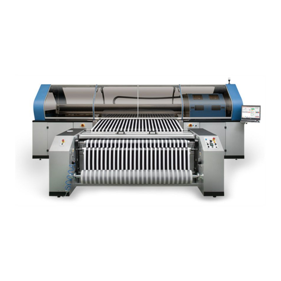
Chapter 2 Outline explanation Outline Explanation ML Tiger-1800B MK II is an inkjet printer for fabric. This machine is used for printing images and patterns on various fabrics. It was developed to enable printing on various fabrics in the textile market. - Page 29 Chapter 2 Outline explanation Idle rollers Pneumatic clutch conditioner Air shaft Compressed air gun The procedure for loading and unloading a fabric roll is described below: Procedure FABRIC LOAD - UNLOAD Referen Mode Indication Feature Figure Remove the air shaft from the safety chuck. below Insert the air shaft into the paper tube of the dough roll.
- Page 30 Chapter 2 Outline explanation Feed the fabric roll. With the compressor connected to the machine, inject Figure compressed air into the air shaft. below Turn on the pneumatic brake system and adjust the pressure with the regulator. Start the operation of this machine. When printing of the fabric is completed, stop the machine and push the check valve, the compressed air will come out of the air shaft.
-
Page 31: Main Parts Of Machine
Chapter 2 Outline explanation Option The following options can be used for feeding fabric. Shaking unit with centering Big roll unit Small roll unit with centering Main Parts of Machine Main belt The belt consists of two conveyor rollers (one is motorized) and a rubber belt. On the surface of the belt there is a bedding layer that makes the fabric that passes under the printhead completely adhere and stabilize. - Page 32 Chapter 2 Outline explanation Pressure roller The pressure roller is placed at the initial position of the belt and brings the fabric into close contact with the belt to prevent the occurrence of wrinkles that may affect the final printed fabric. Furthermore, it removes air bubbles between the belt and the fabric.
- Page 33 Chapter 2 Outline explanation Carriage This unit carries the print head and moves it vertically in response to the movement of the belt. When the belt stops, the unit operates, moves one or more times, and prints the specified image. The carriage is designed to accommodate 2 print heads in each of 8 independent modules (16 print heads in total).
- Page 34 Chapter 2 Outline explanation Procedure Squeegee movement Mode Operation Referen If the belt is not moving, the squeegee blade does not touch the belt because the washing tank is at a low position. AUT. During the cleaning operation, the tank is lifted by the pneumatic piston, so the squeegee blade and the belt are in contact.
- Page 35 Chapter 2 Outline explanation Ink feeding unit Supply genuine ink to the print head attached to the carriage. Ink is contained in eight tanks in the cabinet on the right side of this machine. Rear Front Layout of the ink tanks...
-
Page 36: Overall Dimensions
Chapter 2 Outline explanation Overall Dimensions Dimensions of this machine Below is the maximum dimension (standard model) of this machine. Table Feature Data ► Maximum length ≈ 2800 [mm] ► Maximum width ≈ 5670 [mm] ► Maximum height ≈ 2030 [mm] 2-10... -
Page 37: Identification Of This Machine
• Type Tiger-1800B MKII It is prohibited to remove the nameplate and replace it with another nameplate of the same type. If the nameplate accidentally breaks or comes off from the machine, you are obliged to notify Mimaki and request a replacement label. - Page 38 Chapter 2 Outline explanation 2-12...
- Page 39 Chapter 3 Usage Precautions This chapter describes the intended use, unauthorized use, and the like of this machine. The Intended Use ........3-2 Unauthorized Use ........3-2 Emergency Stop by Operator ....3-2 The Service Life of This Machine ....3-2...
-
Page 40: Chapter 3 Usage Precautions
Chapter 3 Usage Precautions The Intended Use ML Tiger-1800B MK II is intended for use only when observing all of the following data. Table Feature Data ► Print width 1850 [mm] ► Belt width 2000 [mm] ► Print technology Inkjet print head x 16 Roll axial feeding unit with brake ►... - Page 41 Chapter 4 Installation This chapter describes the installation of this machine. Aptitude of Workers ........4-2 Preparing the Installation Site ....4-2 Installation Requirement ......4-3 Loading, Placement, Installation procedure 4-3 Lifting Procedure ........4-4 Unpacking and Placement ......4-5 Connection ..........
-
Page 42: Chapter 4 Installation
Chapter 4 Installation Outline Since this machine is divided into main units, it is easy to transport and install. Follow the instructions in this chapter for transportation and installation work, and only specialized workers should do. • It is necessary to identify all the places handling the machine in advance from the place secured for transportation to the installation place and to check in advance whether there is a danger zone. -
Page 43: Installation Requirement
• Electromagnetic field: Do not expose this unit, especially the cabinet, to a magnetic field that may interfere with opera- tion. • Mimaki assumes no responsibility for any illegal operation of this unit or operation that does not match the specification specified when using this unit under conditions other than the above. -
Page 44: Lifting Procedure
Chapter 4 Installation • When installing, check whether the machine is damaged during transportation. Lifting Procedure We recommend using a bridge crane with appropriate characteristics when lifting the main parts of this machine. When lifting the packing containing the accessories, use a forklift. •... -
Page 45: Unpacking And Placement
Chapter 4 Installation Unpacking and Placement This machine is delivered in a fully assembled state. Follow the instructions given in this manual for transportation and installation work, only by specialized workers. • Install this machine in a place correctly paved in advance by the purchaser. The floor of the installation place should be able to support the weight of the machine sufficiently after installing all parts. - Page 46 As soon as you receive this machine, please check whether parts are damaged or missing. If damage occurs to this machine or accessories are lost, contact Mimaki's Assembly Director promptly. Thoroughly examine the box and package before taking out the contents from the packaging, such as the parts of this machine.
-
Page 47: Connection
Chapter 4 Installation Connection The size of electrical connection, hydraulic connection, pneumatic connection (if any) should be appropriately performed in accordance with the technical data table described in this manual, taking into consideration the durability of the equipment. To make electrical connections, follow the general installation rules for preparation and commissioning. Specified connection should be done by a qualified and authorized personnel. -
Page 48: Storage Condition
Chapter 4 Installation Connection of water supply and discharge In order to operate the belt cleaning unit properly, it is necessary to properly connect the tube with the inner diameter of 16 mm to the solenoid valve. In case of washing water discharge, before starting this machine, make sure that the washing water drain pipe is properly connected and water can be discharged properly. - Page 49 Chapter 4 Installation Storage location characteristics When storing, place this machine in a place with the following characteristics. Indoor with 7000 x 4000 [mm] Height 4000 [mm] At the storage location, sufficient mobility and controllability must be ensured so that official approval workers can safely do lifting of equipment safely.
- Page 50 Chapter 4 Installation 4-10...
-
Page 51: Chapter 5 Push Button Panel
Chapter 5 Push Button Panel This chapter describes the push button panel. Work Station ..........5-2 Push Button Panel (P02) ......5-4 Emergency Pushbutton (PEM) ....5-4... - Page 52 Chapter 5 Push Button Panel Work Station The machine has one PC monitor and four buttons, as shown in the figure below. PC Monitor Operation The operator should stay close to the PC monitor or the button when operating this machine (especially in the following cases).
- Page 53 Chapter 5 Push Button Panel Push button panel (P01) The push button panel (P01) is located on the left side of the PC screen. Below is a description of the buttons of the push button panel (P01). CONTROL VOLTAGE Power supply lamp: When this lamp is lit, power is supplied to this unit and the main switch is turned on.
-
Page 54: Emergency Pushbutton (Pem)
Chapter 5 Push Button Panel Push Button Panel (P02) The push button panel (P02) is located on the right side of the feeding unit. Below is a description of the buttons of the push button panel (P02). PNEUMATIC BRAKE ADJUSTMENT ON - OFF Pneumatic control lever: When tilted upward, adjustment of the pneumatic brake applying tension to the fabric to be extended becomes effective. - Page 55 Chapter 6 QPrint (Software) This chapter describes how to use Qprint, the software used with this machine. Print Data ..............6-2 Startup screen ..............6-2 Print tab ...............6-3 Print queue tab ............6-5 Machine tab ..............6-6 Settings Tab ..............6-8 Basic Operation (printing) ..........6-11 Various Functions ............6-13 List of main functions ..........6-13...
-
Page 56: Chapter 6 Qprint (Software)
Chapter 6 QPrint (Software) Print Data Startup screen Name Overview Remarks • Selecting / outputting a print file. Print • Cleaning manually. Print tab(p.6-3) • Perform belt jog. Each function Print queue • Register Print file in Print queue. Print queue tab(p.6-5) Machine •... -
Page 57: Print Tab
Chapter 6 QPrint (Software) Print tab Name Function Remarks Width Display the width of the print file. Cannot be changed N.repeats Select the number of print file repetitions. Printing area Height Select the output length of Print file. Pos.X Select the print origin. Print File Select the print origin. - Page 58 Chapter 6 QPrint (Software) Name Function Remarks Belt pass Displays the feed amount of one feed. Correct the landing position for bidirectional Offset Print adjustment. quality NozzleRecovery Nozzle recovery function (ON / OFF). Advanced Set MAPS. MAPS functions(p.6-23) 21 Start Start printing.
-
Page 59: Print Queue Tab
Chapter 6 QPrint (Software) Print queue tab Name Function Remarks Width Display the width of the print file. Cannot be changed N.repeats Select the number of print file repetitions. Printing area Height Select the output length of print file. Pos.X Select the print origin. -
Page 60: Machine Tab
Chapter 6 QPrint (Software) Machine tab Name Function Remarks Effective when 1 Connect Connect with PLC. disconnected (Machine Lump: gray) Effective when 2 Disconnect Disconnect from the PLC. connected (Machine Lump: green) 3 IP: Display the IP address of the PLC. 4 Port: Display PLC port. - Page 61 Chapter 6 QPrint (Software) Name Function Remarks Forward Jog Turn on / off the forward jog. Belt jog Reverse Jog Turn on / off the reverse jog. Jog speed Set the jog speed. Stop time Set the belt heater stop time. Belt Heater Belt heater Heating...
-
Page 62: Settings Tab
Chapter 6 QPrint (Software) Settings Tab Make various settings. • Password 1: qualijet • Password 2: lameccanica (1) Settings tab screen (at startup) quali lijet qualijet If the password is correct, the screen will change automatically (2) Settings tab screen (after entering password 1) lameccanica... - Page 63 Chapter 6 QPrint (Software) (3) Settings tab screen (after entering Password 2) Name Unit Function Remarks Pressure value for Purge Pressure value for Print Delay time for Purge Soft MKII disabled Delay time for Purge (control by firmware) Normal Delay time for Purge Hard Printing Carriage speed mt / m Parking - Carriage speed...
- Page 64 Chapter 6 QPrint (Software) Name Unit Function Remarks Cleaning solution pump • Pump output of cleaning solution speed Cleaning Station pump • Wiper cleaning time before wiping - Before wiping Cleaning Station pump • Wiper cleaning time after wiping - After wiping Cleaning pump reduction •...
-
Page 65: Basic Operation (Printing)
Chapter 6 QPrint (Software) Basic Operation (printing) Thumbnail display 6-11... - Page 66 Chapter 6 QPrint (Software) 1. Select the print tab. 2. Select the print file. The thumbnail of the selected print file is displayed on the thumbnail screen. If the print file does not contain a thumbnail, the thumbnail of the last printed print file is displayed.
-
Page 67: Various Functions
Chapter 6 QPrint (Software) Various Functions List of main functions Function Overview Use timing (examples) Manual Cleaning Recover nozzle clogging. • There is a nozzle clogging. Test print Check the nozzle status. • There is a nozzle clogging. • Grainy. Bidirectional adjustment Check / set the bidirectional adjustment value. - Page 68 Chapter 6 QPrint (Software) Manual cleaning Perform manual cleaning to recover from nozzle clogging. Cleaning procedure [Print Tab] 1. Select the cleaning level. Refer to [1.2.6 Ink Usage volume] of Maintenance manual for ink usage. 2. Make sure Spray is enabled. If Spray is not enabled, flushing after cleaning will not be performed, causing nozzle clogging.
- Page 69 Chapter 6 QPrint (Software) Test print function Print the test pattern to be used for checking the nozzle status Procedure to confirm nozzle status 1. Print the test pattern. 2. Check the test pattern and confirm the nozzle status. ...
- Page 70 Chapter 6 QPrint (Software) Bidirectional adjustment function • Adjust bidirectional gap Bidirectional adjustment is necessary when changing the head height or changing the media thickness or type. • You can use patterns to examine the appropriate adjustment value. Bidirectional adjustment procedure 1.
- Page 71 Chapter 6 QPrint (Software) o Determine bidirectional adjustment value by examining bidirectional adjustment pattern 1. Determine bidirectional adjustment value by checking the printed bidirectional adjustment pattern. • Look at the bidirectional adjustment pattern and look for a position where the reference line (upper vertical line) and the adjustment line (lower vertical line) overlap.
- Page 72 Chapter 6 QPrint (Software) o Set the bidirectional adjustment value 1. Set bidirectional adjustment value in “Bidirectional offsets” of “MACHINE” screen. Set the bidirectional adjustment value determined in Determine bidirectional adjustment value by examining bidirectional adjustment pattern.(p.6-17) or the bidirectional adjustment value determined from the bidirectional deviation situation of the printed material.
- Page 73 Chapter 6 QPrint (Software) ColorBar function To discharge (print) stably, it is necessary to use ColorBar in this tool. • We recommend to use ColorBar on this tool in this machine. • When Colorbar is added to the image data using Tx-Link, ColorBar itself is thinned out at the boundary of the pass due to the effect of MAPS, and the ejection stability may decrease at both ends of the head.
- Page 74 Chapter 6 QPrint (Software) • Ink drop order Ink type Sb510 Rc500 Y + Lk M + Bl C + R K + Or *Secondary color bar. In the case of 8color, paths 5 to 8 are superimposed on paths 1 to 4. No nozzle status can be confirmed with 8 colors.
- Page 75 Chapter 6 QPrint (Software) ColorBar setting procedure [Print Tab] 1. Select Position. 2. Select Printing Level. The color bar condition selected in Print Tab is also applied to the Print file registered in the Print queue. 6-21...
- Page 76 Chapter 6 QPrint (Software) Feed correction function The feeding amount of media can be corrected. Enter the feed correction value in the “Feed offset” box of “Print” screen. • The feeding amount of the media is adjusted by the set feed correction value. •...
- Page 77 Chapter 6 QPrint (Software) MAPS functions Due to the effect of MAPS, the boundary of the path is printed with gradation. This improves banding due to color unevenness and feed accuracy. MASK: Gradient area MAPS can be set to Auto or Manual. In Manual mode, Speed and Smooth are parameters and can be set under the following conditions.
- Page 78 Chapter 6 QPrint (Software) MAPS Smooth: Change the density gradient in the MASK area (gradation). (100 to 0%) • MAPS Smooth behavior The smooth percentage is the concentration difference between the lower and upper parts of the MASK region. The appropriate value for Smooth differs depending on the print data.
- Page 79 Chapter 6 QPrint (Software) Auto cleaning function By using Auto Cleaning, cleaning is automatically performed during printing or standby, and the nozzle state is maintained or improved. Recommended settings are shown below to ensure discharge stability. Recommended settings In Printing Offline Ink type Interval*...
- Page 80 Chapter 6 QPrint (Software) Auto cleaning setting method o [In Printing] [Machine Tab] 1. Select In printing. 2. Select enable / disable of auto cleaning during printing. 3. Select the cleaning level. 4. Enable flushing after cleaning. 5. Set the Auto Cleaning interval for printing distance or printing time. 6-26...
- Page 81 Chapter 6 QPrint (Software) o [Offline] [Machine Tab] 1. Select “Offline”. 2. Select enable / disable of auto cleaning during standby. 3. Select the cleaning level. 4. Enable flushing after cleaning. 5. Set the cleaning cycle and flushing interval. 6-27...
- Page 82 Chapter 6 QPrint (Software) Belt Heater Function The belt heater plays a role of supplementing the adhesive force when the adhesive force of the adhesive layer decreases. Do not set the belt heater operating time to 5 seconds or more, or the belt heater output to 80% or more.
- Page 83 Chapter 6 QPrint (Software) Pass / layer settings Improve the quality of products by setting Pass / Layer. Increase the number of passes: If you are concerned about banding Increase the number of layers: When the density is insufficient Pass / layer setting method [Print Tab / Print queue Tab] 1.
- Page 84 Chapter 6 QPrint (Software) Pre feed / Final feed Function Set the feed amount before and after printing. Pre feed [mm]: There is a feed stripe between the first and second scans. Final feed [m]: To dry the work after printing. ...
- Page 85 Chapter 6 QPrint (Software) Print queue function Register print file in the print queue. Use this when you want to print multiple print files unattended. The Print file registered in the Print queue is given the ColorBar set by Print Tab at the time of output.
- Page 86 Chapter 6 QPrint (Software) 7. Delete all print files in the queue list. Press the Clear button. 8. If you want to change the print conditions of the selected Print file in the Queue list, select any job. After changing the conditions, press the Save button. Duplicate print file is registered with Add button.
- Page 87 Chapter 7 Operation, Adjustment, and Maintenance This chapter describes the basic operation method for this machine, as well as adjustment methods and maintenance. Training to Workers (Operators) ....7-2 Operators ..........7-2 Operator Work ........... 7-2 Preparation Before Starting Work ..... 7-2 Transport of Fabric ........
-
Page 88: Chapter 7 Operation, Adjustment, And Maintenance
Chapter 7 Operation, Adjustment, and Maintenance Training to Workers (Operators) • The personnel (operators and maintenance personnel) must participate to an on-site training by the Mimaki’s engineer and they understand all the information provided in the operation manual(this manual), especially accident prevention and safety regulations. -
Page 89: Transport Of Fabric
Chapter 7 Operation, Adjustment, and Maintenance When the RESET EMERGENCY button goes out, reset the software alarm. End of procedure Transport of Fabric Procedure Transport of fabric Mode Indication Operation Reference FABRIC LOAD - Load the fabric roll to the air shaft. UNLOAD Pass the fabric through two idle rollers. -
Page 90: Printer
SWITCH] electrical box to 0 to turn off the voltage. End of procedure • Inform Mimaki beforehand if you stop the machine for more than 2 days. Mimaki maintenance workers need to carry out long-term preservation treatment of the head. -
Page 91: Procedure For Cleaning And Adhesive Application
• Cleaning agents used for cleaning and adhesive for application include toxic and flammable substances. • We recommend that you follow all safety instructions supplied by the supplier carefully. • Mimaki is not responsible for the results of not following these guidelines. Preparation of Belt Cleaning Unit The machine is equipped with two rotating brushed belts. -
Page 92: Replacing Squeegee Blade
Chapter 7 Operation, Adjustment, and Maintenance Adjust the squeegee blade in the following cases. When water droplets are attached to the belt When noise and vibration increase Use the relevant control function to lower the rear part of the tank. Unlock the washing tank and remove it from the machine. - Page 93 Chapter 7 Operation, Adjustment, and Maintenance Squeegee blade Squeegee blade installed correctly not installed correctly Adjustment of squeegee blades then tighten the screws once the correct position is reached End of procedure Required material for applying adhesive to the belt Table Feature Data...
- Page 94 Chapter 7 Operation, Adjustment, and Maintenance Set the belt jog reverse direction mode. Place the doctor to apply the agent to the support and evenly apply the first adhesive layer to the belt. We recommend that you attach an initial point (mark) Figure to the adhesive tape so that you can see that the belt below...
- Page 95 Chapter 7 Operation, Adjustment, and Maintenance Once the adhesive is evenly spread over the entire surface of the belt, the operation is complete. Remove the doctor using a PET film (width 60 cm). Place the plastic stripe in front of the doctor while the belt is Figure moving at reduced speed.
-
Page 96: Belt Cleaning Procedure
Chapter 7 Operation, Adjustment, and Maintenance Belt Cleaning Procedure If you need to remove the adhesive after using the printer, follow the procedure below. Procedure Belt cleaning procedure Mode Indication Operation Reference Remove the washing tank so that the solvent used for cleaning will not damage the belt. -
Page 97: Change Wiper Blade
Chapter 7 Operation, Adjustment, and Maintenance Change Wiper Blade Estimated wiper replacement timing is once every 2 weeks. • The operator should wear safety glasses and protective gloves before starting replacement work. Open the QPrint software. Select Maintenance page. Select the [Head Maintenance Placement] [Start] button. Move the carriage to the maintenance space. - Page 98 Chapter 7 Operation, Adjustment, and Maintenance Remove the wiper blade from the wiper holder and then replace the blade with a new one. • Use the same wiper holder again. • Make sure that you attach the wiper blade in the correct orientation. Attach the wiper holder to the wiper holder mounting block.
-
Page 99: Replacing Ink Tank
Chapter 7 Operation, Adjustment, and Maintenance Replacing Ink Tank If "INK NEAR END" is displayed on QPrint screen the ink level is low. Although you can continue printing, there is a risk that ink will run out during printing. We recommend that you replace the ink tank as soon as possible. - Page 100 Chapter 7 Operation, Adjustment, and Maintenance Remove the fitting from the cap of the ink tank and remove the ink tank from the ink tank tray • When replacing the ink tank on the back side, first remove the ink tank in front. Rear Front Layout of the ink tanks...
- Page 101 Chapter 7 Operation, Adjustment, and Maintenance Place the new ink tank on the ink tank tray and attach the fitting [How to read a tag] 1 ST ST: Supply tube Circulation tube Path number (1 to 8) • When removing multiple ink tanks, make sure that the tubes are connected properly and the ink tanks are placed correctly.
-
Page 102: Refill The Cleaning Solution (Wiper Cleaning Solution)
Chapter 7 Operation, Adjustment, and Maintenance Refill the Cleaning Solution (Wiper Cleaning Solution) Confirm the remaining amount once a day in the cleaning solution tank Estimated refill period: once every 24 hours of printing time (in the case of auto cleaning 30 min) If the remaining amount of cleaning solution is insufficient, “Cleaning Solution LOW level Alarm”... - Page 103 Chapter 7 Operation, Adjustment, and Maintenance Return the cleaning solution tank to the specified position and attach the cap. Press QPrint's "Clear Alarms". • When "Cleaning Solution LOW level Alarm" disappears on QPrint and cleaning will be available. 7-17...
-
Page 104: Installation / Replacement Of Waste Tank
Chapter 7 Operation, Adjustment, and Maintenance Installation / Replacement of Waste Tank A waste tank (20L tank recommended) is required for the waste at cleaning and the waste of the water absorption roller unit. Confirm the amount of waste once a day in the waste tank and exchange it periodically. Comply with the laws and regulations of each local government / region for disposal of the waste. - Page 105 Chapter 7 Operation, Adjustment, and Maintenance Replacement procedure (1) Gently pull up the waste hose from the waste tank. • There is a possibility that the waste fluid splashes if you raise the tank vigorously. Spare tank Waste tank (2) Put the ink that remains in the waste hose into the waste tank.
- Page 106 Chapter 7 Operation, Adjustment, and Maintenance 7-20...
-
Page 107: Chapter 8 Safety Devices And Residual Risks
Chapter 8 Safety Devices and Residual Risks This chapter describes the safety devices attached to this machine, as well as residual risks. Safety Devices .......... 8-2 Residual Risks .......... 8-3 Mandatory Requirements and Safety Precautions ..........8-3... -
Page 108: Safety Devices
Safety Devices • The customer is obliged to inform Mimaki in case of defect and / or malfunction of the protection systems and any potentially dangerous situation. Emergency stop button Press the emergency stop button to immediately stop any operation in progress and deactivate the controls (Emergency condition). -
Page 109: Residual Risks
Chapter 8 Safety Devices and Residual Risks Residual Risks The operator should confirm that there are no foreign objects such as dust and oil in this machine. For this reason, the operator needs to schedule a cleaning procedure at the end of the shift, with the machine switched off and with the help of assistants. - Page 110 Chapter 8 Safety Devices and Residual Risks...
- Page 111 Chapter 9 Maintenance This chapter describes the maintenance of this machine to be performed by the operator. Maintenance Overview ..........9-2 Ordinary Maintenance ..........9-2 Scheduled Maintenance ..........9-2 Summary Table for Maintenance Work ....... 9-3 Special Maintenance ........... 9-4 Troubleshooting ............
-
Page 112: Chapter 9 Maintenance
The operator can only perform the cleaning work of this machine. Mechanical work and electrical work are performed by a maintenance worker. Special maintenance work is done by an official approved by Mimaki. Ordinary Maintenance Regular maintenance work is carried out without determining the specific cycle in advance. It is based on operator's judgment and common sense. -
Page 113: Summary Table For Maintenance Work
For more information on maintaining the print head, see the dedicated manual. • Mimaki assumes no responsibility for any injury or property damage caused by negligence in carrying out the scheduled maintenance operations of the print head. -
Page 114: Special Maintenance
• Establish the checks to be carried out after the operation. • Evaluate whether the support of Mimaki’s technical staff is required. Or ensure a remote technical support for sugges- tions and precautions to be taken. For this purpose, contact Mimaki directly. -
Page 115: Troubleshooting
Chapter 9 MAINTENANCE Troubleshooting • It is necessary to have accurate technical knowledge and professional skills to carry out any work of this machine. Required the operation by specialized staffs. • The staff must create all conditions required by the laws in force concerning safety in permanent or temporary jobs, or both. - Page 116 Chapter 9 MAINTENANCE Error Error displayed Cause Measures Cleaning Station Cleaning station 1. Click the [Reset Machine] button on the Print page, and then click the sensors Alarm sensor error [Clear Alarms] button. 2. If the Alarm is displayed again after clicking the [Clear Alarms] button, Cleaning Station turn off the power of the internal PC and then the main power of the Forward motor...
- Page 117 Chapter 9 MAINTENANCE Error Error displayed Cause Measures 1. Set the media again so that the media does not float off the belt, and click the [Clear Alarms] button on the Print page. If the media continues to float: 2. Adjust the pressure of the pressure roller. 3.
- Page 118 Chapter 9 MAINTENANCE Error Error displayed Cause Measures 1. Check if there is a hole in the media coming out of the UNWINDER unit. If there is a hole, feed the media until it comes out of the print area, then click the [Clear Alarms] button on the Print page. The media end was 2.
- Page 119 Chapter 9 MAINTENANCE Error Error displayed Cause Measures 1. Check the following (1) Check that the DRYERJET emergency switches (2 places) are released. At this time also check whether the emergency switch on the main unit is released. (2) Make sure that there is no clogging near the media insertion slot of DRYERJET.
- Page 120 Chapter 9 MAINTENANCE Error Error displayed Cause Measures 1. Click the [Alarms] button on the Print page 2. If the Alarm is displayed again after clicking the [Clear Alarms] button, Communication DRYERJET turn off the power of the DRYERJET once and then turn it on again error between Communication after a while.
- Page 121 Chapter 9 MAINTENANCE Error Error displayed Cause Measures 1. Check the connection part of the Big Roll Cardan joint. If the cardan joint is not connected to the trolley, connect it. 2. Click the [Clear Alarms] button on the Print page Cardan joint error of 3.
- Page 122 Chapter 9 MAINTENANCE Error list (Other) Error Error displayed Cause Measures 0104:YY(________)+35V RECVR An error occurred in the 010E:YY(________)FROM control PCB. CLEAR 010F:YY(________)FROM WRITE 0115:YY(________)PCB MAIN-F1 0116:YY(________)PCB MAIN-F2 0122:YY(________)CHECK :SDRAM Turn off the power of the internal PC and then the main power of the 0123:YY(________)PRAM DATA machine in this order, and then turn on 0124:YY(________)PRAM ADDR...
- Page 123 Chapter 9 MAINTENANCE Error Error displayed Cause Measures 0171:YY(______ZZ)NEW HEAD CONNECT Recognized a new head ZZ indicates a head number. connection. 1: Head 1 (rear) 2: Head 2 (front) 0172:YY(________)Main PCB Q6 Check 018A:YY(________)Main PCB V_CORE An error has occurred in the power supply.
- Page 124 Chapter 9 MAINTENANCE Error Error displayed Cause Measures Make sure that the ink tank is set 0531:09(ZZZZZZZZ)INKTANK correctly, that there is no impact, and SENSOR that there is no load on it. ZZZZZZZZ indicates a path Turn off the power of the internal PC number.
- Page 125 Chapter 9 MAINTENANCE Error Error displayed Cause Measures 061B:09(ZZZZZZZZ)INK SUPPLY Check the remaining ink level in the ink ZZZZZZZZ indicates a path tank and execute [CLEAR ALARM]. number. Ink can not be supplied to If the Alarm appears again, contact 1: Path 1 the sub-tank.
- Page 126 Chapter 9 MAINTENANCE Error Error displayed Cause Measures 073F:YY(______ZZ)HD HEATER CTRL ERR The head heater cannot ZZ indicates a head number. Turn off the power of the internal PC be controlled. 1: Head 1 (rear) and then the main power of the 2: Head 2 (front) machine in this order, and then turn on again after a while.
- Page 127 Chapter 9 MAINTENANCE Error Error displayed Cause Measures 0B27:YY(________)HD LOGIC FUSE 0B28:YY(________)HD DRIVER Print head control PCB FUSE error 0B29:YY(________)HD VLT ERR 0B2A:YY(______ZZ)HD HEATER FUSE 0B35:YY(______ZZ)HD VLT ERR ZZ indicates a head number. HD driver voltage 26V Turn off the power of the internal PC 1: Head 1 (rear) abnormal and then the main power of the...
- Page 128 Chapter 9 MAINTENANCE Error Error displayed Cause Measures Print preparation is not C052:00(ZZZZZZZZ)PRINT C0 52 completed at the start of MODE ERROR(2) printing. Turn off the power of the internal PC C053:00(ZZZZZZZZ)PRINT Printing is not in progress C0 53 and then the main power of the MODE ERROR(3) at the start of printing.
- Page 129 Chapter 9 MAINTENANCE Error Error displayed Cause Measures C302:00(ZZZZZZZZ)Parameter is Operating parameter Turn off the power of the internal PC C3 02 not set does not exist. and then the main power of the machine in this order, and then turn on again after a while.
-
Page 130: Dismantling
Mimaki will not approve the adaptability of the parts to be reused after the final removal of this machine, either explicitly or implicitly. - Page 131 Operation Manual ML Tiger-1800B MK II December 2019 MIMAKI ENGINEERING CO.,LTD. 2182-3 Shigeno-otsu, Tomi-shi, Nagano 389-0512 JAPAN D203446-10-26122019...
- Page 132 © MIMAKI ENGINEERING CO., LTD.2019 FW:1.00...
Need help?
Do you have a question about the ML Tiger-1800B MK II and is the answer not in the manual?
Questions and answers