MIMAKI ML Tiger-1800B MK III Operation Manual
Color inkjet printer
Hide thumbs
Also See for ML Tiger-1800B MK III:
- Operation manual (86 pages) ,
- Operation manual (132 pages)

Related Manuals for MIMAKI ML Tiger-1800B MK III


Summary of Contents for MIMAKI ML Tiger-1800B MK III
- Page 1 COLOR INKJET PRINTER ML Tiger-1800B MK III MIMAKI ENGINEERING CO., LTD. https://mimaki.com/ D203491-11 Original instructions...
- Page 2 • This manual explains the operation and maintenance of “ML Tiger-1800B MK III” (hereafter referred to as this machine). Read carefully and fully understand it before using this machine. • The machine has to be used only for the purpose agreed in the contract and has to be operated under conditions compatible with those specified in the manual.
-
Page 4: Table Of Contents
TABLE OF CONTENTS Chapter 1 Introduction Positioning of Operation Manual ............1-2 Purpose of Operation Manual ............1-2 Documents Supplied with This Machine ...........1-2 Manufacturer's Authorization .............1-2 Normative Standard ................1-2 Handling of This Manual ..............1-3 Safety Precaution ................1-5 Electrical Equipment ................1-7 General Safety Instructions ...............1-7 Warning Label ...................1-9 Warning Label Display Position ............1-12 Chapter 2... - Page 5 Flow to printing ..................6-9 Operation during printing ..............6-18 SYSTEM ALARM .................6-21 Indication when an error is occurred ..........6-21 Operation restrictions when an alarm occurs ........6-23 How to clear the alarm ..............6-24 Cleaning ..................6-25 Cleaning at any time ................6-25 Auto maintenance setting ..............6-27 Nozzle recovery ................6-30 MAINTENANCE ................6-38 Description of maintenance content ..........6-38...
- Page 6 Troubleshooting .................9-5 Dismantling ..................9-27...
- Page 7 Chapter 1 Introduction This chapter describes the Operation Manual, safety precautions, and the like. Positioning of Operation Manual ....1-2 Purpose of Operation Manual ....1-2 Documents Supplied with This Machine ... 1-2 Manufacturer's Authorization ..... 1-2 Normative Standard ........1-2 Handling of This Manual ......
-
Page 8: Chapter 1 Introduction
This operation manual (this manual) is produced according to the manual production procedure and is regarded as a part of the product's components. This manual has been revised as necessary, and the revision history is managed appropriately. All copying and publishing rights concerning this manual and accompanying related documents are protected by Mimaki's copyright. Purpose of Operation Manual This operation manual provides information so that workers (operators) can work with this machine to do their work safely. -
Page 9: Handling Of This Manual
Chapter 1 Introduction Handling of This Manual This manual is considered part of the product and must be stored and used for the entire lifetime of the machine. When you lend or transfer this machine, hand the manual with the machine. Keep this manual in a location that is easily accessible. - Page 10 Limitations of warranty Unless there is a specific agreement on the contract, Mimaki shall use it for the normal operation of this machine (only if it is used in accordance with the instructions stated in this manual and maintenance manual), to manufacture this machine we guarantee the compliance of the machine against the quality of the material and the technical features described in this document.
-
Page 11: Safety Precaution
Chapter 1 Introduction Safety Precaution Special attention is required for the following work. • When apply the adhesive on the belt, turn ON the key. • When operate the belt at low speed, turn OFF the belt heater. • Places where there is a possibility of contact with the Primary power supply should not be opened in the power ON state (electrical unit of main unit, carriage rear cover, and electric unit in heater electric unit). - Page 12 Chapter 1 Introduction • Be careful not to get your hands caught in the cleaning unit. • Be careful not to pinch your hands on the tension bar. • Be careful not to pinch your hands on the pressure roller. •...
-
Page 13: Electrical Equipment
Chapter 1 Introduction • Be careful not to pinch your hands etc. on the top cover of the heater. • Be careful not to catch your hands at the belt edge cover. Electrical Equipment This equipment has been designed and manufactured to carry out specifications and functions agreed with customers. It is not allowed to use the machine for other uses, as there may be a danger to human life or a failure of this machine or your product. - Page 14 Chapter 1 Introduction • The owner is responsible for the disclosure of this manual to all operators who operate this machine. Safety indications Safety is secured under normal operating conditions. However, in order to further improve the level of safety at work, it is recommended that operators should adopt an attitude of security alert.
-
Page 15: Warning Label
Chapter 1 Introduction Warning Label Warning label Part No. Label name Fig. Caution label-movable part M903330 Caution label-works M912054 Caution label-pinching M907935 Label-Danger voltage M910931 Caution label-front cover falling M901581 Caution label M909381 Caution label-Y bar M903764 Caution label- UV power voltage M914168 Caution label-applying glue... - Page 16 Chapter 1 Introduction M914167 Caution label-belt M903404 Caution label-movable part M903239 Caution label-Temperature Prohibition label Part No. Label name Fig. Prohibition label-prohibition on removal of safety guard M903406 Ground label M913888 Label-C.10 mark M916752 Tiger1800B Mk3 rated label M915604 Caution label- two outlet M915603 Power connection label 1-10...
- Page 17 Chapter 1 Introduction M915602 Feeding relay connector rated label M915605 X12ETH-3 Mark label M915601 PC outlet rated label M915598 DRYERJET rated label M915608 Main switch label 1-11...
-
Page 18: Warning Label Display Position
Chapter 1 Introduction Warning Label Display Position • Do not remove the warning label on the machine. • Make sure that the label is clearly legible and not covered with parts. • If the label deteriorates, contact us and change it. (1) Electrical box M907935_Label-Danger voltage M903406-00_Ground label... - Page 19 Chapter 1 Introduction (2) Belt Front Caution label-applying glue Caution label-belt M901581_Caution label Rear M901581_Caution label M912054_Caution label- pinching Caution label-belt (3) Carriage M903406_Ground label M909381_Caution label-Y bar M907935_Label-Danger voltage 1-13...
- Page 20 Chapter 1 Introduction (4) Left front cover M903330_Caution label-works M907935_Label-Danger voltage (5) Left rear cover M903330_Caution label-works (6) Right rear cover M903330_Caution label-works M903330_Caution label-works 1-14...
- Page 21 Chapter 1 Introduction (7) Right side cover M903330_Caution label-works (8) Station M903330_Caution label-works (9) Model label M913888_Label-C.10 mark 1-15...
- Page 22 Chapter 1 Introduction (10)Plastic cover Front M910931_Caution label-front cover falling: 4 pieces 1-16...
- Page 23 Chapter 1 Introduction Rear M910931_Caution label-front cover falling: 4 pieces 1-17...
- Page 24 Chapter 1 Introduction (11)Display label Electrical Box side M916752 Tiger1800B Mk3 rated label M915604 Caution label - two outlet M915605 X12ETH-3_Mark label M915602 Feeding Relay connector rated label M915603 Power connection label 1-18...
- Page 25 Chapter 1 Introduction M915601 PC outlet rated label 1-19...
- Page 26 Chapter 1 Introduction 1-20...
- Page 27 Chapter 2 Outline Explanation This chapter provides an outline of the main unit for this machine and describes its features. Outline Explanation ........2-2 Description of Machine Units ....2-2 Feeding Unit ..........2-2 Main Parts of Machine ....... 2-5 Overall Dimensions ........
-
Page 28: Chapter 2 Outline Explanation
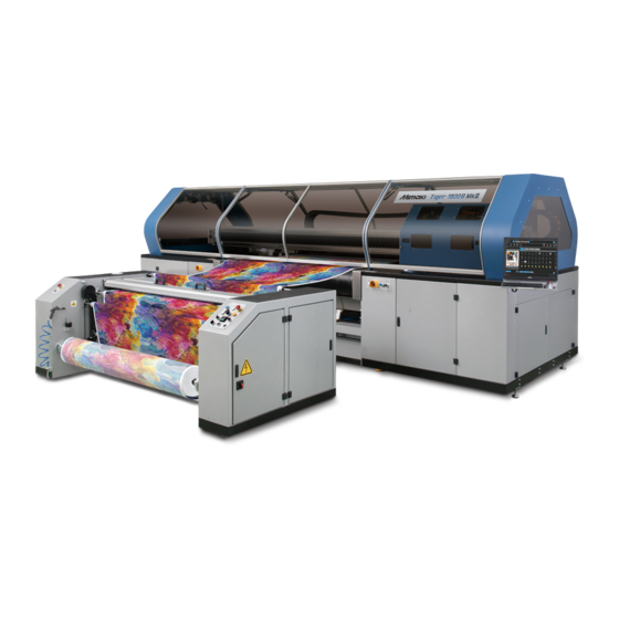
Chapter 2 Outline explanation Outline Explanation ML Tiger-1800B MK III is an inkjet printer for textile. This machine is used for printing images and patterns on various fabrics or transfer paper (hereafter “media”). Print quality is guaranteed by the belt carrying the media, the pressure rollers adhering the media to the belt, and the belt cleaning unit removing the excess ink adhered to the belt. - Page 29 Chapter 2 Outline explanation Idle rollers Pneumatic clutch conditioner Air shaft Compressed air gun The procedure for loading and unloading a media roll is described below: Procedure media LOAD - UNLOAD Referen Mode Indication Feature Figure Remove the air shaft from the safety chuck. below Insert the air shaft into the paper tube of the dough roll.
- Page 30 Chapter 2 Outline explanation Feed the media roll. With the compressor connected to the machine, inject Figure compressed air into the air shaft. below Turn on the pneumatic brake system and adjust the pressure with the regulator. Start the operation of this machine. When printing of the media is completed, stop the machine and push the check valve, the compressed air will come out of the air shaft.
-
Page 31: Main Parts Of Machine
Chapter 2 Outline explanation Option The following options can be used for feeding media. Shaking unit with centering Big roll unit Small roll unit with centering Main Parts of Machine Main belt The belt consists of two conveyor rollers (One is motor driven) and a rubber belt. On the surface of the belt there is a bedding layer that makes the media that passes under the printhead completely adhere and stabilize. - Page 32 Chapter 2 Outline explanation Pressure roller The pressure roller is placed at the initial position of the belt and brings the media into close contact with the belt to prevent the occurrence of wrinkles that may affect the final printed media. Furthermore, it removes air bubbles between the belt and the media.
- Page 33 Chapter 2 Outline explanation Carriage This unit carries the print head and moves it vertically in response to the movement of the belt. When the belt stops, the unit operates, moves one or more times, and prints the specified image. The carriage is designed to accommodate 2 print heads in each of 8 independent modules (Print head: up to 16).
- Page 34 Chapter 2 Outline explanation Procedure Squeegee movement Mode Operation Referen If the belt is not moving, the squeegee blade does not touch the belt because the washing tank is at a low position. AUT. If you select to start belt feeding, the tank is lifted by the air cylinder, so the squeegee blade and the belt are in contact.
- Page 35 Chapter 2 Outline explanation Ink feeding unit Supply genuine ink to the print head attached to the carriage. Ink is contained in eight tanks in the cabinet on the right side of this machine. Rear Front Layout of the ink tanks...
-
Page 36: Overall Dimensions
Chapter 2 Outline explanation Overall Dimensions Dimensions of this machine Below is the maximum dimension (standard model) of this machine. Table Feature Data ► Maximum length ≈ 2800 [mm] ► Maximum width ≈ 5670 [mm] ► Maximum height ≈ 2030 [mm] 2-10... -
Page 37: Identification Of This Machine
• Type Tiger-1800B MKIII It is prohibited to remove the nameplate and replace it with another nameplate of the same type. If the nameplate accidentally breaks or comes off from the machine, you are obliged to notify Mimaki and request a replacement label. - Page 38 Chapter 2 Outline explanation 2-12...
- Page 39 Chapter 3 Usage Precautions This chapter describes the intended use, unauthorized use, and the like of this machine. The Intended Use ........3-2 Unauthorized Use ........3-2 Emergency Stop by Operator ....3-2 The Service Life of This Machine ....3-2...
-
Page 40: Chapter 3 Usage Precautions
Chapter 3 Usage Precautions The Intended Use ML Tiger-1800B MK III is intended for use only when observing all of the following data. Table Feature Data ► Print width 1850 [mm] ► Belt width 2000 [mm] ► Print technology Inkjet print head x 16 Roll axial feeding unit with brake ►... - Page 41 Chapter 4 Installation This chapter describes the installation of this machine. Aptitude of Workers ........4-2 Preparing the Installation Site ....... 4-2 Installation Requirement ....... 4-3 Loading, Placement, Installation procedure .. 4-3 Lifting Procedure ........... 4-4 Unpacking and Placement ......4-5 Connection ............
-
Page 42: Chapter 4 Installation
Chapter 4 Installation Outline Since this machine is divided into main units, it is easy to transport and install. Follow the instructions in this chapter for transportation and installation work, and only specialized workers should do. • It is necessary to identify all the places handling the machine in advance from the place secured for transportation to the installation place and to check in advance whether there is a danger zone. -
Page 43: Installation Requirement
• Electromagnetic field: Do not expose this unit, especially the cabinet, to a magnetic field that may interfere with opera- tion. • Mimaki assumes no responsibility for any illegal operation of this unit or operation that does not match the specification specified when using this unit under conditions other than the above. -
Page 44: Lifting Procedure
Chapter 4 Installation • When installing, check whether the machine is damaged during transportation. Lifting Procedure We recommend using a bridge crane with appropriate characteristics when lifting the main parts of this machine. When lifting the packing containing the accessories, use a forklift. •... -
Page 45: Unpacking And Placement
Chapter 4 Installation Unpacking and Placement This machine is delivered in a fully assembled state. Follow the instructions given in this manual for transportation and installation work, only by specialized workers. • Install this machine in a place correctly paved in advance by the purchaser. The floor of the installation place should be able to support the weight of the machine sufficiently after installing all parts. - Page 46 As soon as you receive this machine, please check whether parts are damaged or missing. If damage occurs to this machine or accessories are lost, contact Mimaki's Assembly Director promptly. Thoroughly examine the box and package before taking out the contents from the packaging, such as the parts of this machine.
-
Page 47: Connection
Chapter 4 Installation Connection The size of electrical connection, hydraulic connection, pneumatic connection (if any) should be appropriately performed in accordance with the technical data table described in this manual, taking into consideration the durability of the equipment. To make electrical connections, follow the general installation rules for preparation and commissioning. Specified connection should be done by a qualified and authorized personnel. -
Page 48: Storage Condition
Chapter 4 Installation Connection of water supply and discharge In order to operate the belt cleaning unit properly, it is necessary to properly connect the tube with the inner diameter of 16 mm to the solenoid valve. In case of washing water discharge, before starting this machine, make sure that the washing water drain pipe is properly connected and water can be discharged properly. - Page 49 Chapter 4 Installation Storage location characteristics When storing, place this machine in a place with the following characteristics. Indoor with 7000 x 4000 [mm] Height 4000 [mm] At the storage location, sufficient mobility and controllability must be ensured so that official approval workers can safely do lifting of equipment safely.
- Page 50 Chapter 4 Installation 4-10...
- Page 51 Chapter 5 Push Button Panel This chapter describes the push button panel. Work Station ..........5-2 Push button panel (P01) ......5-3 Push Button Panel (P02) ......5-4 Emergency switch (PEM) ......5-4...
-
Page 52: Chapter 5 Push Button Panel
Chapter 5 Push Button Panel Work Station The machine has one PC monitor and four push-button-panels, as shown in the figure below. PC Monitor Operation The operator should stay close to the PC monitor or the button when operating this machine (especially in the following cases). -
Page 53: Push Button Panel (P01)
Chapter 5 Push Button Panel Push button panel (P01) The push button panel (P01) is located on the left side of the PC screen. Below is a description of the buttons of the push button panel (P01). CONTROL VOLTAGE Power supply lamp: When this lamp is lit, power is supplied to this unit and the main switch is turned on. -
Page 54: Push Button Panel (P02)
Chapter 5 Push Button Panel Push Button Panel (P02) The push button panel (P02) is located on the right side of the feeding unit. Below is a description of the buttons of the push button panel (P02). PNEUMATIC BRAKE ADJUSTMENT ON - OFF Pneumatic control lever: When tilted upward, adjustment of the pneumatic brake applying tension to the media to be extended becomes effective. - Page 55 Chapter 6 Basic usage This chapter This section describes how to operate this machine with the touch panel. Introduction ..........6-2 Cleaning ..........6-25 Description of screen configuration .... 6-2 Cleaning at any time ........ 6-25 Status bar ..........6-3 Auto maintenance setting ......
-
Page 56: Chapter 6 Basic Usage
Chapter 6 Basic usage Introduction This section describes how to operate the printer and other various operations and settings using the touch panel. Description of screen configuration (1) Status bar (2) MENU (3) Quick menu (4) Content Name Description Shows printer status. Status bar Menus organized by function group. -
Page 57: Status Bar
Chapter 6 Basic usage Status bar Overview Shows printer status. Screen description (3) SYSTEM ALARM (1) PRINTER STATUS (2) INK STATUS Item Description Explanation Printer status type Printing PRINTER STATUS Pause The icon changes depending on printer status. Idling Under maintenance Type of icon indicating the remaining ink level Ink near end... -
Page 58: Menu
Chapter 6 Basic usage MENU Overview The menu consists of each function group. The function of each selected menu is displayed in the content area. Screen description (5) SYSTEM (4) HISTORY (3) SETTING (2) MAINTENANCE (1) PRINT MENU Description Main functions •... -
Page 59: Explanation Of Operation Method
Chapter 6 Basic usage Explanation of operation method Touch panel / mouse operation method This touch panel can be operated with a mouse. Controller When to use Touch panel Mouse Operation: Tap Operation: Left click • Select a job to print •... -
Page 60: Each Control Operation Method
Chapter 6 Basic usage Each control operation method This section describes how to operate each item. Control name When to use ON setting ON/OFF Switch When selecting ON / OFF OFF setting Radio button When selecting one of multiple options Input number When entering number + / –... -
Page 61: Explanation Of Screen When Executing Process
Chapter 6 Basic usage Explanation of screen when executing process This section explains the processing screen when processing is executed. Explanation of screen when executing process Transition of screen when executing process 1. Process execution 2. Processing screen 3-1. Process completion 3-2. -
Page 62: Print Operation
Chapter 6 Basic usage Print operation This section describes the job management and print operation procedure of the selected job. Description of the print content Print operation is performed from the Print menu. Print content screen structure Item Description The print status is displayed. •... -
Page 63: Flow To Printing
Chapter 6 Basic usage Flow to printing Print a job created with the RIP application by the following procedure. 1. Import of a job (P.6-10) 2. Selection of a job to print (P.6-14) 3. Setting of print conditions (P.6-15) 4. Start of printing (P.6-17) 5. -
Page 64: Import Of A Job
Chapter 6 Basic usage 1. Import of a job When printing, import the job to the internal PC. This section describes how to import a job from a removable disk and how to import through a network. You can directly select a job on a removable disk, but it is recommended that you perform an import before printing, as printing may be delayed. - Page 65 Chapter 6 Basic usage (Left screen) Select the job to be imported. • Move to the folder that contains the job you want to import and press and hold the job to select. (Right screen) Specify the import destination. • Move to the folder where you want to copy the job. Specifying the import destination [ADD NEW FOLDER]...
- Page 66 Chapter 6 Basic usage <Create folder> dialog If the folder name is not entered, a folder named “NewFolder” is created. If a folder with the same name already exists, the <Create folder> dialog will be closed without creating a new folder. Perform import.
- Page 67 Chapter 6 Basic usage 1-2. Import from network. A network shared folder is set in the printer's internal PC. Jobs can be imported to the shared folder from another PC connected to the LAN. The recommended import method is described below. •...
-
Page 68: Selection Of A Job To Print
Chapter 6 Basic usage 2. Selection of a job to print Tap the job to be printed from the Job list area to display the <Print condition selection> dialog. If a job displayed in the JOB LIST tab or JOB HISTORY tab is deleted from the PC, the dialog will be displayed, but an error will occur when you execute printing. -
Page 69: Setting Of Print Conditions
Chapter 6 Basic usage 3. Setting of print conditions Enter a condition in the <Print condition selection> dialog to start printing. <Print condition selection> dialog 6-15... - Page 70 *1 Each repeat and print length varies depending on the set value and image size. *2 MAPS: MAPS function (Mimaki Advanced Pass System) is a function that disperses the boundary of the pass and makes the feed stripe inconspicuous. Depending on the printing conditions, such as 1 pass printing, the MAPS mask may be visible.
-
Page 71: Start Of Printing
Chapter 6 Basic usage 4. Start of printing After specifying the print conditions, tap the [Print] button to start printing. Print button When printing starts, the <Print condition selection> dialog box is closed and the job information and progress being printed are displayed in the JOB STATUS area. -
Page 72: Operation During Printing
Chapter 6 Basic usage Operation during printing You can pause/restart or cancel printing by tapping the [Print operation] buttons. [Print operation] buttons Pause Pause the print operation. Tap the [Pause] button in the Print status field. Pause and change to [Restart] button. The processing screen is displayed until the pause is completed. -
Page 73: Restart
Chapter 6 Basic usage Restart Restarts printing of the paused job. Tap the [Restart] button in the JOB STATUS field. Cancel Cancels the print. Tap the [Cancel] button in the JOB STATUS field. The processing screen is displayed until the cancellation is completed. -> Completed <Print cancel>... -
Page 74: Cleaning During Printing
Chapter 6 Basic usage Cleaning during printing Cleaning can be performed at any time during printing. Perform cleaning from the QUICK MENU or MAINTENANCE MENU. Cleaning at any time (P.6-25) Refer to “ ” for cleaning. After the pause, the carriage returns to the station and cleaning is performed. After the cleaning is completed, printing resumes automatically. -
Page 75: System Alarm
Chapter 6 Basic usage SYSTEM ALARM The SYSTEM ALARM field displays the alarm information that occurred on the machine. This section describes an error indication and corrective actions. Indication when an error is occurred When an error occurs, an alarm icon and error details are displayed in the [SYSTEM ALARM] area. If you tap the [DETAIL] button when an alarm occurs, the detailed information and the [CLEAR ALARM] button will be displayed and you can clear the alarm. - Page 76 Chapter 6 Basic usage Alarm icon Information (error level: 0) Icon color Alarm content Handling method Blue Occurs when treatment is required, such as ink Check the alarm details and take action near end. according to the information. Continue printing. System warning (error level: 1) Icon color Alarm content...
-
Page 77: Operation Restrictions When An Alarm Occurs
Chapter 6 Basic usage Operation restrictions when an alarm occurs When an error occurs, the operation is restricted according to the error level. This section describes the operation according to the printer status and error level. Idling status If an error occurs in the idling state, the operation is restricted according to the error level. Level Operation restriction Description... -
Page 78: How To Clear The Alarm
Chapter 6 Basic usage How to clear the alarm When an error occurs, take action according to the error level, and then clear the alarm from the alarm details screen. Tap the [CLEAR ALARM] button. Tap the [CLEAR ALARM] button The processing screen is displayed until the alarm clear is completed. -
Page 79: Cleaning
Chapter 6 Basic usage Cleaning This section explains about Head cleaning. * Auto cleaning setting during standby or printing is performed from the [SETTING] menu. Cleaning at any time It is performed when the nozzle check result in the test print is bad or when a nozzle clogging is found during printing. When cleaning can be performed 1) When the printer is in idle 2) During printing (Can be executed without pausing operation.) - Page 80 Chapter 6 Basic usage Select the Cleaning Mode. • Select a cleaning mode from the Mode selection field on the cleaning execution screen. Main application of each cleaning mode Mode Application Time required Soft When refreshing the nozzle surface, such as before printing about 50 seconds Normal When multiple nozzles are clogging...
-
Page 81: Auto Maintenance Setting
Chapter 6 Basic usage Auto maintenance setting By using Auto maintenance, cleaning is automatically performed during printing or idling, and the nozzle condition is maintained or improved. The cycle starts when Auto maintenance is set. • If cleaning is performed at any time, the cycle will be restarted. Recommended settings The following is the recommended setting for ensuring ejection stability. -
Page 82: Auto Maintenance Setting
Chapter 6 Basic usage Auto maintenance setting Auto maintenance setting in idle Description Auto maintenance in idle On / Off Time cycle (min) Cleaning mode (Soft, Normal, Hard) Flushing between cleanings On / Off Flushing count when 4 is set ... - Page 83 Chapter 6 Basic usage Auto maintenance setting during printing Description Auto maintenance during printing On / Off Select the cycle type of the print distance / print time Print length (m) when selecting the print length in 2 Printing time (min) when selecting the print time in 2. Cleaning mode (Soft, Normal, Hard) 6-29...
-
Page 84: Nozzle Recovery
Chapter 6 Basic usage Nozzle recovery When nozzles missing cannot be improved by cleaning, other normal nozzles can be used as alternatives for printing; Nozzle recovery system (NRS). Nozzle recovery is applied only during multi-pass printing. (600 x 600 dpi 2 passes or more, 600 x 1200 dpi 4 passes or more, 1200 x 1200 dpi 4 passes or more) •... -
Page 85: Creating Nozzle Recovery Data
Print the nozzle recovery pattern Set the media for printing nozzle recovery pattern • Set the dedicated media for nozzle recovery (white PET or Mimaki Vision Jet-X-162) in the print area. Select the nozzle recovery pattern. 1. Select the [PRINT] menu 2. - Page 86 Chapter 6 Basic usage Print the Nozzle recovery pattern • Print the selected Nozzle recovery pattern. Do not change the settings of Pass, Layer, Print direction, Print Speed, or MAPS settings. Otherwise, the pattern may not be printed properly. Cut out the printed nozzle recovery pattern The nozzle recovery pattern shown below (pattern of the 4-color model) is printed.
- Page 87 Chapter 6 Basic usage Scan the extracted nozzle recovery pattern with a scanner Read the extracted nozzle recovery pattern into the internal PC with a scanner. Read the nozzle recovery pattern using the attached scanner. if use the other scanner the analysis process to detect missing nozzles may fail. Start the scanning application attached to the scanner •...
- Page 88 Chapter 6 Basic usage Reading the nozzle recovery pattern 1. Scanner setting Item Settings Resolution 1200dpi Read format BITMAP Others Make settings so that no processing is added to the scanned image. Professional Mode 1200dpi Un-checking all After the above setting, push the Scan. 2.
- Page 89 Chapter 6 Basic usage Create nozzle recovery data Using the analysis application, analyze the scanned image and generate the nozzle recovery data. In the analysis application, errors may be displayed for various reasons. Error indication shows only the error code and some errors do not show a message indicating the error information.
- Page 90 Chapter 6 Basic usage 2. Check that the color order and ink set is the same as the selected image data. 3. Tap the [Analyze] button to start the analysis. Confirm and modify the nozzle missing analysis results • When analysis is completed, analysis results are displayed in the lower left. •...
-
Page 91: Enable The Nozzle Recovery Function
Chapter 6 Basic usage 2. Modify the result After checking the nozzle condition if the nozzle condition is no problem it is possible to change the result from “NG” to “OK”. To change to “OK”, select the relevant nozzle and tap the [Change to OK] button. Creating nozzle recovery data •... -
Page 92: Maintenance
Chapter 6 Basic usage MAINTENANCE This section describes maintenance methods such as Cleaning operation and head cleaning. Auto cleaning setting in idle or print is performed from the [SETTING] menu. Description of maintenance content Maintenance operations are performed from the maintenance menu. Maintenance content screen configuration Select and execute a maintenance item from [Maintenance list]. -
Page 93: Operation Of Control Panel
Chapter 6 Basic usage Operation of Control panel Feed Control,Pressure roller operation, Carriage out operation, and Wiper cleaning pump operation can be performed from the MPC menu and the machine operation panel. Display the operation panel Select [ MAINTENANCE] > [Control panel] > [Control panel] to display the [Feed Control] and [Pump Control] dialogs. -
Page 94: Setting
Chapter 6 Basic usage SETTING This section explains Settings related to print quality and auto maintenance, peripheral device operating conditions and mechanical operation and others that can be set by the user. Description of the setting content Setting operations are performed from the SETTING MENU. Description of the setting content screen Select the item to be set from the [Print] item in Config list field. -
Page 95: Example Of Setting Procedure - Color Bar
Chapter 6 Basic usage Example of setting procedure - Color bar An example of color bar settings is shown below. Select setting item. • Select [ SETTING] MENU > [Print] > [Color bar] to display the <Color bar setting> dialog. Enter the set value. -
Page 96: Feature Description
Chapter 6 Basic usage Feature description STATUS bar PRINTER STATUS Shows printer status. Name Icon Description Initial state Idling Printer status icon Printing Paused Maintenance Printer status – Idling / Printing / Paused / Cleaning explanation [DETAIL] button Tap to display the machine status. Display the machine status Displays the status of Capping / Pressure roller / Forward jog / Reverse jog / Heater / Vent... -
Page 97: Ink Status
Chapter 6 Basic usage INK STATUS Displays ink color and ink remaining for each ink slot in graph and percentage (%). When the ink level is low, an icon is displayed at the bottom right of each ink. Name Icon Description Normal display (Remaining ink level: 26% ~ 100%) : Display icon at the... -
Page 98: Menu
Chapter 6 Basic usage MENU Menus are organized by function, and the function items of the selected menu are displayed in the content area. Name Icon Description Reference Perform the job management and print operations. [PRINT] MENU P.6-46 Perform printer maintenance. Perform operations related to [MAINTENANCE] MENU P.6-51 each maintenance. - Page 99 Chapter 6 Basic usage MENU Reference Auto setting [Pressure roller] P.6-57 Pressure roller Auto setting Washing tank [Washing unit] P.6-58 Washing brush Wash water supply Obstacle sensor SETTING Winder-Unwinder Belt heater [Machine] P.6-59 Vent fan Light On/Off Nozzle recovery Scanner [Nozzle recovery] P.6-60 NozzleRecoveryTool...
-
Page 100: [Print] Menu
Chapter 6 Basic usage [PRINT] MENU Perform the job management and printing operations. [JOB LIST] tab Name Icon Description Job name display Displays the name of the job being printed. Job thumbnail display Displays the job thumbnail. Print progress display Displays the print progress. - Page 101 Chapter 6 Basic usage Name Icon Description 10 Go up one folder level Displays the folder one level above. Current folder name Tap to display the name of the folder that is currently display open. 12 Update folder The currently folder is updated. Data in the currently folder is displayed as a Job thumbnail display thumbnail.
- Page 102 Chapter 6 Basic usage [JOB QUEUE] tab Name Icon Description JOB QUEUE tab Displays a list of jobs waiting to be printed. The number of jobs waiting to be printed is Number of waiting jobs displayed. When you tap a job, the <Print Condition> dialog is Queuing job selection displayed and you can change the print condition.
- Page 103 Chapter 6 Basic usage [JOB HISTORY] tab Name Icon Description JOB HISTORY tab Displays a list of printed jobs. Tap the job to display the <Print condition selection> Job selection dialog and you can reprint. 6-49...
- Page 104 Chapter 6 Basic usage [TEST PATTERN] tab Name Icon Description TEST PATTERN tab Displays a list of jobs for the test pattern. To the home folder Shows the home folder. Go up one folder level Displays the folder one level above. Current folder name Tap to display the name of the folder that is currently display...
-
Page 105: [Maintenance] Menu
Chapter 6 Basic usage [MAINTENANCE] MENU Perform maintenance and maintenance settings. [Cleaning] Recommended Name Description Initial value: value: The [Cleaning] and [Powerful cleaning] menus are Cleaning – – displayed. Select the Cleaning Mode (Soft / Normal / Hard) and Cleaning Normal Normal perform. - Page 106 Chapter 6 Basic usage [Auto maintenance] Recommended Name Description Initial value: value: The [Cleaning (Idle)] and [Cleaning (Print)] menus are Auto maintenance – – displayed. The following items can be set. – – • Idle cleaning On / Off • Execution interval (hours) Cleaning (Idle) •...
- Page 107 Chapter 6 Basic usage [Jog operation] Recommended Name Description Initial value: value: The [Forward jog], [Reverse jog], [Jog speed] menu will Jog operation – – be displayed. Forward jog Operate Forward jog with [Start], [Stop] buttons. – – Reverse jog Operate Reverse jog with [Start], [Stop] buttons.
- Page 108 Chapter 6 Basic usage [Control panel] Name Description Control panel The operation panel window is displayed. Feed operation, Pressure roller operation, Carriage out operation, and Wiper cleaning Control panel pump operation can be performed. [Machine condition check] Name Description Machine condition check A status confirmation window will be displayed. Ink supply Executes the ink supply check operation and displays the execution time.
-
Page 109: [Setting] Menu
Chapter 6 Basic usage [SETTING] MENU Make various settings. [Print] Recommended Name Description Initial value: value: The [Color bar], [Pre feed], [Dry feed], and [Head gap] Print – – menus are displayed. The following items can be set. – – •... - Page 110 Chapter 6 Basic usage [Bi-direction adjustment] Recommended Name Description Initial value: value: The [Bi-direction adjustment], [ └ 600Std pattern], Bi-direction adjustment – – [ └ 600Hi pattern], [ └ 1200Std pattern], and [ └ 1200Hi pattern] menus are displayed. The following items can be set. –...
- Page 111 Chapter 6 Basic usage [Media] Recommended Name Description Initial value: value: Media The [Media setting] menu is displayed. – – Media setting Set the origin (500 to 1950mm). – [Pressure roller] Recommended Name Description Initial value: value: The [Auto setting] and [Pressure roller] menus are Pressure roller –...
- Page 112 Chapter 6 Basic usage [Washing unit] Recommended Name Description Initial value: value: The [Auto setting], [Washing tank], [Washing brush], and Washing unit – – [Wash water supply] menus are displayed. Auto setting Set On / Off. Tap the [Operate] or [Stop] button to control the washing Washing tank –...
- Page 113 Chapter 6 Basic usage [Machine] Recommended Name Description Initial value: value: The [Obstacle sensor], [Winder-Unwinder], [Belt heater], Machine – – [Vent fan], and [Light On/Off] menus are displayed. Obstacle sensor Set the obstacle sensor On / Off. Set whether to enable / disable the winder/unwinder. –...
- Page 114 Chapter 6 Basic usage [Nozzle recovery] Recommended Name Description Initial value: value: The [Nozzle recovery], [Scanner], and Nozzle recovery – – [NozzleRecoveryTool] menus are displayed. Nozzle recovery Set nozzle recovery function On / Off. Start the scanner software to read the nozzle recovery Scanner –...
-
Page 115: [History] Menu
Chapter 6 Basic usage [HISTORY] MENU Perform maintenance and maintenance settings. Name Description Print The print job history is displayed. Maintenance The maintenance history is displayed. Alarm The alarm history is displayed. Controller The operation history is displayed. Parts Mainly, the history of the attached head is displayed. The results of Ink supply, Purge pressure pump, Ink circulation, Air release valve, and Condition Head heater temperature executed from the condition menu are displayed in the history. -
Page 116: [System] Menu
Chapter 6 Basic usage [SYSTEM] MENU Perform maintenance and maintenance settings. [System config] Recommended Name Description Initial value: value: System config The [Language] menu is displayed. – – Language Set the language (English / Japanese). English – [Information] Name Description Information The [HDD Capacity], [Version], [License], and [Log collection tool] menus are displayed. - Page 117 Chapter 6 Basic usage [Document] Name Description Document The [Operation guide] and [Alarm list] menus are displayed. Operation guide The operation guide is displayed. Alarm list The alarm list is displayed. [Maintenance mode] This is a menu for service purpose. It can not be used. 6-63...
- Page 118 Chapter 6 Basic usage [Power] Name Description The [System reconfiguration], [Reset machine], [Reboot PC], and [Shutdown PC] menus Power are displayed. A confirmation dialog for system reconfiguration is displayed. System reconfiguration Tap [OK] to reinitialize. The confirmation dialog for machine reset is displayed. Reset machine Tap [OK] to reset the machine.
-
Page 119: Quick Function
Chapter 6 Basic usage Quick function Execute the frequently used functions directly from shortcut icons. Name Icon Description Forward jog Perform the forward jog operation. Stop Forward Pressure roller Move up or down the pressure roller. Down Test print Perform a test print. Cleaning Perform cleaning. - Page 120 Chapter 6 Basic usage 6-66...
- Page 121 Chapter 7 Operation, Adjustment, and Maintenance This chapter describes the basic operation method for this machine, as well as adjustment methods and maintenance. Training to Workers (Operators) ....7-2 Operators ..........7-2 Operator Work ........... 7-2 Preparation Before Starting Work ..... 7-2 Transport of Fabric ........
-
Page 122: Chapter 7 Operation, Adjustment, And Maintenance
Training to Workers (Operators) • The personnel (operators and maintenance personnel) must participate to an on-site training by the Mimaki’s engineer and they understand all the information provided in the operation manual (this manual), especially accident prevention and safety regulations. -
Page 123: Transport Of Media
Chapter 7 Operation, Adjustment, and Maintenance Transport of media Procedure Transport of media Mode Indication Operation Reference media LOAD - Load the media roll to the air shaft. UNLOAD Pass the media through two idle rollers. P02 - No.3 Pressure roller Lift the pressure roller. -
Page 124: Printer
SWITCH] electrical box to 0 to turn off the voltage. End of procedure • Inform Mimaki beforehand if you stop the machine for more than 2 days. Mimaki maintenance workers need to carry out long-term preservation treatment of the head. -
Page 125: Procedure For Cleaning And Adhesive Application
• Cleaning agents used for cleaning and adhesive for application include toxic and flammable substances. • We recommend that you follow all safety instructions supplied by the supplier carefully. • Mimaki is not responsible for the results of not following these guidelines. Preparation of Belt Cleaning Unit The machine is equipped with two rotating brushed belts. -
Page 126: Adjust The Squeegee Blade
Chapter 7 Operation, Adjustment, and Maintenance Adjust the Squeegee Blade • The installed squeegee blades could be different according to final configuration of the machine. It is necessary to reconfirm the height of the squeegee blade. Especially check if noise increases or water drops are seen on the belt. -
Page 127: Replacing Squeegee Blade
Chapter 7 Operation, Adjustment, and Maintenance Replacing Squeegee Blade The squeegee blade is a rubber device used to remove washing water from the belt. Because the squeegee blade is made of rubber, it will not be possible to properly clean the work due to the influence of wear, depending on the type of treatment after a certain period of time. - Page 128 Chapter 7 Operation, Adjustment, and Maintenance Applying adhesive to the belt For use in the textile printing model, we recommend that you prepare an adhesive at a 4:1 ratio of resin bonded type Atrafix ML/K ATR 1947 and neutral base Unilevel ML ATR 1948. * The composition of the adhesive material depends on the media used.
- Page 129 Chapter 7 Operation, Adjustment, and Maintenance Use the appropriate command on the operator panel to initiate a manual backward movement. Figure Apply the adhesive evenly to the belt. below Once the adhesive is evenly spread over the entire surface of the belt, the operation is complete.
-
Page 130: Belt Cleaning Procedure
Chapter 7 Operation, Adjustment, and Maintenance Belt Cleaning Procedure If you need to remove the adhesive after using the printer, follow the procedure below. Procedure Belt cleaning procedure Mode Indication Operation Reference Remove the washing tank so that the solvent used for cleaning will not damage the belt. -
Page 131: Change Wiper Blade
Chapter 7 Operation, Adjustment, and Maintenance Change Wiper Blade Estimated wiper replacement timing is once every 2 weeks. • The operator should wear safety glasses and protective gloves before starting replacement work. • Replacement of the wiper blade can also be performed by using [User maintenance] > [Maintenance wizard] from the [MAINTENANCE] menu in addition to the following methods. - Page 132 Chapter 7 Operation, Adjustment, and Maintenance Attach the wiper holder to the wiper holder mounting block. • Push the wiper holder until the parts of it shown in the dotted circle are engaged with the wiper holder mounting block. • Make sure that the wiper holder does not come off if you pull it from the block. Close the cover.
-
Page 133: Replacing Ink Tank
Chapter 7 Operation, Adjustment, and Maintenance Replacing Ink Tank If "INK NEAR END" is displayed on touch panel the ink level is low. Although you can continue printing, there is a risk that ink will run out during printing. We recommend that you replace the ink tank as soon as possible. - Page 134 Chapter 7 Operation, Adjustment, and Maintenance Remove the fitting from the cap of the ink tank and remove the ink tank from the ink tank tray • When replacing the ink tank on the back side, first remove the ink tank in front. Rear Front Layout of the ink tanks...
- Page 135 Chapter 7 Operation, Adjustment, and Maintenance Place the new ink tank on the ink tank tray and attach the fitting [How to read a tag] 1 ST ST: Supply tube CT: Circulation tube Path number (1 to 8) • When removing multiple ink tanks, make sure that the tubes are connected properly and the ink tanks are placed correctly.
-
Page 136: Refill The Cleaning Solution (Wiper Cleaning Solution)
Chapter 7 Operation, Adjustment, and Maintenance Refill the Cleaning Solution (Wiper Cleaning Solution) Confirm the remaining amount once a day in the cleaning solution tank Estimated refill period: once every 24 hours of printing time (in the case of auto cleaning 30 min) If the remaining amount of cleaning solution is insufficient, “F466 Cleaning Solution LOW level Alarm”... - Page 137 Chapter 7 Operation, Adjustment, and Maintenance Return the cleaning solution tank to the specified position and attach the cap. Tap the [CLEAR ALARM] button on the touch panel. • “[1]: F466: 11 Cleaning Solution LOW level Alarm” alarm disappears and cleaning can be executed. Tap the [CLEAR ALARM] button 7-17...
-
Page 138: Installation / Replacement Of Waste Tank
Chapter 7 Operation, Adjustment, and Maintenance Installation / Replacement of Waste Tank A waste tank (20L tank recommended) is required for the waste at cleaning and the waste of the water absorption roller unit. Confirm the amount of waste once a day in the waste tank and exchange it periodically. Comply with the laws and regulations of each local government / region for disposal of the waste. - Page 139 Chapter 7 Operation, Adjustment, and Maintenance Replacement procedure (1) Gently pull up the waste hose from the waste tank. • There is a possibility that the waste fluid splashes if you raise the tank vigorously. Spare tank Waste tank (2) Put the ink that remains in the waste hose into the waste tank.
- Page 140 Chapter 7 Operation, Adjustment, and Maintenance 7-20...
-
Page 141: Chapter 8 Safety Devices And Residual Risks
Chapter 8 Safety Devices and Residual Risks This chapter describes the safety devices attached to this machine, as well as residual risks. Safety Devices .......... 8-2 Residual Risks .......... 8-3 Mandatory Requirements and Safety Precautions ..........8-3... -
Page 142: Safety Devices
Safety Devices • The customer is obliged to inform Mimaki in case of defect and / or malfunction of the protection systems and any potentially dangerous situation. Emergency switch Press the emergency switch to immediately stop any operation in progress and deactivate the controls (Emergency condition). -
Page 143: Residual Risks
Chapter 8 Safety Devices and Residual Risks Residual Risks The operator should confirm that there are no foreign objects such as dust and oil in this machine. For this reason, the operator needs to schedule a cleaning procedure at the end of the shift, with the machine switched off and with the help of assistants. - Page 144 Chapter 8 Safety Devices and Residual Risks Dangerous zone To avoid risks, please never stay in the indicated area (in the red diagonal, below) while the machine is running. • The machine must be operated by a single operator Multiple operators are allowed only in case of loading and unloading rolls.
- Page 145 Chapter 9 Maintenance This chapter describes the maintenance of this machine to be performed by the operator. Maintenance Overview ........9-2 Ordinary Maintenance ........9-2 Scheduled Maintenance ........9-2 Summary Table for Maintenance Work ....9-4 Special Maintenance ..........9-4 Troubleshooting ..........9-5 Error list (PLC) ........... 9-5 Error list (Analysis Application “NZCApp”) ..
-
Page 146: Chapter 9 Maintenance
The operator can only perform the cleaning work of this machine. Mechanical work and electrical work are performed by a maintenance worker. Special maintenance work is done by an official approved by Mimaki. Ordinary Maintenance Regular maintenance work is carried out without determining the specific cycle in advance. It is based on operator's judgment and common sense. - Page 147 For more information on maintaining the print head, see the dedicated manual. • Mimaki assumes no responsibility for any injury or property damage caused by negligence in carrying out the scheduled maintenance operations of the print head.
-
Page 148: Summary Table For Maintenance Work
• Establish the checks to be carried out after the operation. • Evaluate whether the support of Mimaki’s technical staff is required. Or ensure a remote technical support for sugges- tions and precautions to be taken. For this purpose, contact Mimaki directly. -
Page 149: Troubleshooting
Chapter 9 MAINTENANCE Troubleshooting • It is necessary to have accurate technical knowledge and professional skills to carry out any work of this machine. Required the operation by specialized staffs. • The staff must create all conditions required by the laws in force concerning safety in permanent or temporary jobs, or both. - Page 150 Chapter 9 MAINTENANCE Error Error Error displayed Cause Measures level 1. Check the diameter of the wound media. The maximum diameter is φ500mm. If the diameter is over 500mm, replace the roll. 2. If the dancing bar is lowered too much during a jog or feed and the media is slack, readjust it so that it does not slack.
- Page 151 Chapter 9 MAINTENANCE Error Error Error displayed Cause Measures level Carriage sensor Carriage height sensor 1. Tap the [DETAIL] button in [SYSTEM ALARM], and F457 UP position Alarm error tap the [CLEAR ALARM] button. 2. If the alarm appears again even after tapping the Carriage Up Motor F458 [Alarm Clear] button, turn off the power of the built-in...
- Page 152 Chapter 9 MAINTENANCE Error Error Error displayed Cause Measures level 1. Remove the cause of alarm of UNITECH HEATER. 2. Tap the [DETAIL] button in [SYSTEM ALARM], and tap the [CLEAR ALARM] button. UNITECH 3. If the alarm appears again even after tapping the Alarm generated in F469 1 or 2...
- Page 153 Chapter 9 MAINTENANCE Error Error Error displayed Cause Measures level 1. Check if there is a hole in the media coming out of the UNWINDER unit. If there is a hole, feed the media until it comes out of the print area, then tap the [DETAIL] button in [SYSTEM ALARM], and tap the [CLEAR ALARM] button.
- Page 154 Chapter 9 MAINTENANCE Error Error Error displayed Cause Measures level [For Unwinder Paper] 1. Level the dancing bar in the local mode. (Manual feed etc.) 2. Check that the operation mode of the UNWINDER unit is set to Auto. 3. Tap the [DETAIL] button in [SYSTEM ALARM], and tap the [CLEAR ALARM] button.
- Page 155 Chapter 9 MAINTENANCE Error Error Error displayed Cause Measures level 1. Check the following items. (1) Check that the DRYERJET emergency switches (2 places) are released. At this time also check whether the emergency switch on the main unit is released.
- Page 156 Chapter 9 MAINTENANCE Error Error Error displayed Cause Measures level 1. Check the following items. (1) Reset the media. (2) Level the tension bar in the local mode. 2. Tap the [DETAIL] button in [SYSTEM ALARM], and DRYERJET tap the [CLEAR ALARM] button. Media error on F544 Breaking Paper...
- Page 157 Chapter 9 MAINTENANCE Error Error Error displayed Cause Measures level [For Unwinder Paper] It will be displayed if Unwinder bypass is enabled in MPC, so follow the steps below to disable the bypass: 1. Disable [MPC] > [Settings] > [Machine] > [Winder - Unwinder] ->...
- Page 158 Chapter 9 MAINTENANCE Error Error Error displayed Cause Measures level It will be displayed if Winder bypass is enabled in MPC, so follow the steps below to disable the bypass: 1. Disable [MPC] > [Settings] > [Machine] > [Winder- Unwinder] -> [Winder Bypass]. 2.
- Page 159 Chapter 9 MAINTENANCE Error Error Error displayed Cause Measures level 1. Tap the [DETAIL] button in [SYSTEM ALARM], and tap the [CLEAR ALARM] button. 2. If the alarm appears again even after tapping the [Alarm Clear] button, turn off the power of the built-in PC and then the printer.
- Page 160 Chapter 9 MAINTENANCE Error Error Error displayed Cause Measures level 1. Tap the [DETAIL] button in [SYSTEM ALARM], and tap the [CLEAR ALARM] button. 2. If the alarm appears again even after tapping the Big Roll Unwinder Inverter error of Big [Alarm Clear] button, turn off the power of the built-in F796 Inverter Alarm...
-
Page 161: Error List (Analysis Application "Nzcapp")
Chapter 9 MAINTENANCE Error list (Analysis Application “NZCApp”) Error No. Message Error description Cause Corrective action Solution 4610 No indication 1. Execute cleaning to improve the firing condition. 2. Set the pattern correctly and scan the scanner. 4611 No indication 3. -
Page 162: Error List (Other)
Chapter 9 MAINTENANCE Error list (Other) Error Error Error displayed Cause Measures level 1 04 0104:YY(________)+35V RECVR 1 0E 010E:YY(________)FROM CLEAR 1 0F 010F:YY(________)FROM WRITE 1 1F 011F:YY(________)PCB SLIDER 1 15 0115:YY(________)PCB MAIN-F1 1 16 0116:YY(________)PCB MAIN-F2 Turn off the power of the internal PC and then the 1 22 0122:YY(________)CHECK :SDRAM... - Page 163 Chapter 9 MAINTENANCE Error Error Error displayed Cause Measures level 018E:YY(________ZZ)FLS NOT COMP ZZ indicates a head number. 1 8E 1 : Head 1 (rear) 2 : Head 2 (front) Ink ejection control error 018F:YY(_______ZZ)OFFSET START Turn off the power of the ZZ indicates a head number.
- Page 164 Chapter 9 MAINTENANCE Error Error Error displayed Cause Measures level Check that the ink tank is correctly set, that there is no impact, and that there is no load. 0531:09(ZZZZZZZZ)INKTANK SENSOR Turn off the power of the internal PC and then the ZZZZZZZZ indicates a path number.
- Page 165 Chapter 9 MAINTENANCE Error Error Error displayed Cause Measures level Air may have been aspirated. 061A:09(ZZZZZZZZ)INK OVERFLOW Check the remaining ink level in the ink tank and execute ZZZZZZZZ indicates a path number. Detected sub-tank [CLEAR ALARM]. 1 : Path 1 6 1A sensor Limit.
- Page 166 Chapter 9 MAINTENANCE Error Error Error displayed Cause Measures level Make sure that the fitting of 0678:09(ZZZZZZZZ)INK CIRCULATION the tube connected to the ink WARN tank is securely connected, ZZZZZZZZ indicates a path number. An abnormality was and then perform [CLEAR 6 78 1: Route 1 detected in the ink...
- Page 167 Chapter 9 MAINTENANCE Error Error Error displayed Cause Measures level 8 01 0801:YY(________)(C)OPCODE 8 02 0802:YY(________)(C)SWI 8 03 0803:YY(________)(C)PFTCH ABRT 8 04 0804:YY(________)(C)DATA ABRT 8 06 0806:YY(________)FW/SIO bit 8 07 0807:YY(________)FW/SIO wbsy Turn off the power of the 8 0E 080E:YY(________)FW/FROM prm internal PC and then the main power of the machine in...
- Page 168 Chapter 9 MAINTENANCE Error Error Error displayed Cause Measures level CPU2 B 25 0B25:YY(________)HDC DIRECTION Scan control error B 27 0B27:YY(________)HD LOGIC FUSE B 28 0B28:YY(________)HD DRIVER FUSE Print head control PCB error B 29 0B29:YY(________)HD VLT ERR B 2A 0B2A:YY(______ZZ)HD HEATER FUSE 0B35:YY(______ZZ)HD VLT ERR Turn off the power of the...
- Page 169 Chapter 9 MAINTENANCE Error Error Error displayed Cause Measures level MDC Mode_Error The print condition has C051:00(ZZZZZZZZ)PRINT MODE C0 51 not been created at the ERROR(1) start of printing. Turn off the power of the Print preparation is not internal PC and then the C052:00(ZZZZZZZZ)PRINT MODE C0 52 completed at the start...
- Page 170 Chapter 9 MAINTENANCE Error Error Error displayed Cause Measures level MDC Command_Error Turn off the power of the internal PC and then the main power of the machine in this order, and then turn on Received undefined C2 01 C201:00(ZZZZZZZZ)MG Command ERROR again after a while.
- Page 171 Chapter 9 MAINTENANCE Error Error Error displayed Cause Measures level MDC System_Error C9 01 C901:00(ZZZZZZZZ)Program ERROR Program ERROR Turn off the power of the internal PC and then the Unexpected error main power of the machine in C9 98 C998:00(ZZZZZZZZ)EXCEPTION(1) (other than software this order, and then turn on exception, below)
-
Page 172: Dismantling
Mimaki will not approve the adaptability of the parts to be reused after the final removal of this machine, either explicitly or implicitly. - Page 173 Operation Manual ML Tiger-1800B MK III March 2021 MIMAKI ENGINEERING CO.,LTD. 2182-3 Shigeno-otsu, Tomi-shi, Nagano 389-0512 JAPAN D203491-11-25032021...
- Page 174 © MIMAKI ENGINEERING CO., LTD.2020 Tiger Products Install Pack 2.04...
Need help?
Do you have a question about the ML Tiger-1800B MK III and is the answer not in the manual?
Questions and answers