Sign In
Upload
Download
Table of Contents
Contents
Add to my manuals
Delete from my manuals
Share
URL of this page:
HTML Link:
Bookmark this page
Add
Manual will be automatically added to "My Manuals"
Print this page
×
Bookmark added
×
Added to my manuals
Manuals
Brands
Hisense Manuals
Monitor
49WF Series
Quick installation manual
Hisense 49WF Series Quick Installation Manual
Window facing display
Hide thumbs
1
Table Of Contents
2
3
4
5
6
7
8
9
10
11
12
13
14
15
16
17
18
19
20
21
22
23
24
25
26
27
28
29
30
31
32
page
of
32
Go
/
32
Contents
Table of Contents
Bookmarks
Table of Contents
Table of Contents
Safety Precautions
Safety Instruction & Cleaning
Exemptions
Installation
Package Contents
Hanging Installation
Wall-Mount Installation
Installation Requirements
Terminal Connections
Network Connecting
Hdmi Signal Source
Specifications
Advertisement
Quick Links
Download this manual
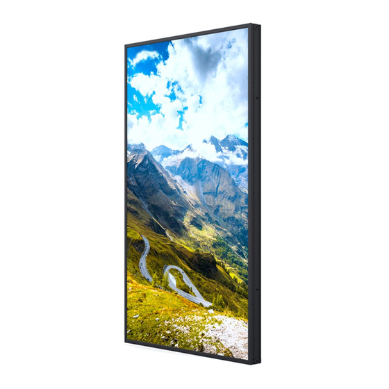
Window Facing Display
Quick Installation Guide
49WF/55WF
Series
www.hisense-b2b.com
Table of
Contents
Previous
Page
Next
Page
1
2
3
4
5
Advertisement
Table of Contents
Need help?
Do you have a question about the 49WF Series and is the answer not in the manual?
Ask a question
Questions and answers
Related Manuals for Hisense 49WF Series
Monitor Hisense 49WF25E Quick Installation Manual
Window facing display (32 pages)
Monitor Hisense 32DM66D Control Manual
(17 pages)
Monitor Hisense Covidien HME2C26 User Manual
(55 pages)
Monitor Hisense Laser TV Display Screen Installation Manual
(15 pages)
Monitor Hisense 55GM60AE User Manual
(25 pages)
Monitor Hisense HME8C55S User Manual
(33 pages)
Monitor Hisense HMD4C27S User Manual
(24 pages)
Monitor Hisense HMD3G21S User Manual
(30 pages)
Monitor Hisense HMC8C86TOA User Manual
(33 pages)
Monitor Hisense HME8C32 User Manual
(46 pages)
Monitor Hisense 65WR6BE User Manual
Vision board (76 pages)
Monitor Hisense HME8C55E User Manual
(42 pages)
Monitor Hisense HMC8C65TOA User Manual
(32 pages)
Monitor Hisense 55SOA25PT User Manual
Outdoor series (18 pages)
Monitor Hisense PDP4211AU User Manual
106cm plasma display tv (20 pages)
Monitor Hisense HME8C58 User Manual
(23 pages)
This manual is also suitable for:
55wf series
55wf25e
49wf45h
49wf25e
55wf45h
Table of Contents
Print
Rename the bookmark
Delete bookmark?
Delete from my manuals?
Login
Sign In
OR
Sign in with Facebook
Sign in with Google
Upload manual
Upload from disk
Upload from URL


Need help?
Do you have a question about the 49WF Series and is the answer not in the manual?
Questions and answers