
Related Manuals for Belden HIRSCHMANN PTN-CSM310-A


Summary of Contents for Belden HIRSCHMANN PTN-CSM310-A
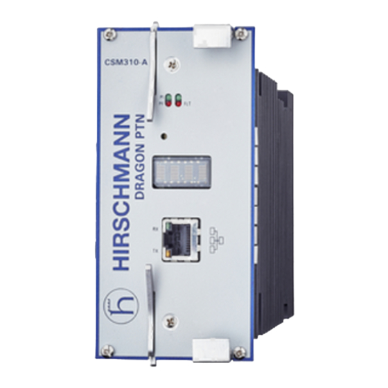
- Page 1 User Manual Installation Dragon PTN Central Switching Module PTN-CSM310-A Central Switching Module PTN-CSM310-A Technical Support Release 02 09/2019 https://hirschmann-support.belden.com...
- Page 2 The naming of copyrighted trademarks in this manual, even when not specially indicated, should not be taken to mean that these names may be considered as free in the sense of the trademark and tradename protection law and hence that they may be freely used by anyone. ©...
-
Page 3: Table Of Contents
Contents INTRODUCTION ......................5 General ....................5 Manual References ................6 MODULE DESCRIPTION ....................6 Front Panel ................... 6 2.1.1 Insert/Remove Module into/from Node ........... 7 2.1.2 LEDs ......................7 2.1.3 Reset Button - Factory Default - Reboot Node .......... 7 2.1.4 Alphanumeric Display ................ - Page 4 Figure 2 HiProvision Management Connector ................12 Figure 3 Dragon PTN Management ..................... 13 Figure 4 SyncE Clock Recovery ....................15 Figure 5 IEEE 1588v2 ........................16 Figure 6 PTN-CSM310-A: Side View .................... 17 Figure 7 Hardware Edition ......................18 Figure 8 Micro SD Memory Card Interface ..................
-
Page 5: Introduction
1. INTRODUCTION 1.1 General This document is valid as of Dragon PTN Release 4.0. This document describes the PTN-CSM310-A Central Switching module (=CSM), which is the heart of the Dragon PTN nodes. This module provides the main processing within the Dragon PTN nodes via an Integrated Ethernet Multilayer Switch and onboard Traffic Manager. -
Page 6: Manual References
1.2 Manual References Table 2 is an overview of the manuals referred to in this manual. ‘&’ refers to the language code, ‘*’ refers to the manual issue. All these manuals can be found in the HiProvision (=Dragon PTN Management System) Help function. Table 2 Manual References Ref. -
Page 7: Insert/Remove Module Into/From Node
2.1.1 Insert/Remove Module into/from Node See ‘Dragon PTN Installation and Operation Manual’ Ref.[2]. CAUTION: 1) Do not touch the heat sink when the CSM is in operation, or when removing the CSM from the node. It can be extremely hot. Risk of getting burned! 2) The CSM could be heavier than expected because of the heat sink. -
Page 8: Alphanumeric Display
Push short: Warm restart: Single CSM: Pushing the RESET button forces a warm start of the CSM without affecting the CSM configuration; Redundant CSMs: Pushing the RESET button on… … both CSMs simultaneously force a warm start without affecting the CSM configuration, the CSM that was active before the reboot becomes the active one again after the reboot;... -
Page 9: Table 5 Display: Reboot Operation
Table 5 Display: Reboot Operation Display Description Normal (re)boot, boot cycle Boot step of the display reboot cycle. Ld1, Ld2, step of the display reboot cycle. The CSM can have two firmware loads (active and spare load) Ld1t, Ld2t onboard that have been uploaded via HiProvision. If load1 is active, load2 is the spare load and vice versa. -
Page 10: Table 7 Csm Display: Error List
Display Description Indicates the switchover state, only possible on the active CSM, after a switchover on user request either via HiProvision or by pushing the NSM switchover button, the state is only briefly displayed. IP <IP Address> This is the 'front IP address' or the IP address of the HiProvision management port on the front panel, which is in the range [172.16.0.1 ->... - Page 11 Display Description Curative Action standby. Pull out the standby CSM, replace the SD card and plug in the CSM again. In both cases above, the new SD card will get a copy of the current CSM configuration after CSM insertion. Processor error on CSM<x>...
-
Page 12: Hiprovision Management Port/Channel
Display Description Curative Action enough input voltage to deliver the normal PoE power (x = 1 or 2). S<x> IFM HWERR The module in slot S<x> has a hardware error. Replace the Interface Module. Example: S4 IFM HWERR The interface slot <x> has a module type Make sure that the configured module in S<x>... -
Page 13: Functional Operation
HiProvision PC Dynamically built (=Dragon PTN Management) Management Channel = DCN Channel Dragon PTN Network Figure 3 Dragon PTN Management b. HiProvision - CSM Connection Scenarios There are multiple connection scenarios possible between the HiProvision PC and the CSM (or Dragon PTN network). Direct connection;... -
Page 14: Central Node Switching
Modules are connected to the active CSM in a star configuration resulting in an individual data bus for each Interface Module. Data transfer is full duplex. See also §2.2.3. 2.2.3 Central Node Switching The switch on the CSM is non-blocking and has following data bus: PTN-CSM310-A: 4 x '1 Gbps / 10 Gbps' ports 24 x '1 Gbps' ports... -
Page 15: Figure 4 Synce Clock Recovery
clock is recovered from an incoming data signal on an Interface Module interface port (e.g. Data1 on a PTN-4-GC-LW module,) and forwarded to the CSM via the backplane, see figure below. The CSM cleans up and redistributes this clock over the entire node to all the interface slots. -
Page 16: Self-Test
b. PTP IEEE 1588v2 (=Precision Time Protocol) The Precision Time Protocol (=PTP), as defined in IEEE 1588v2, is a protocol that manages the distribution of a synchronous timestamp clock (micro-second accuracy), network wide between an external grandmaster clock and its slaves or substations. The CSM verifies that all the Interface Modules in the node have the same node-internal timestamp. -
Page 17: Health Monitor
decides whether the captured (SNMP) trap results in an alarm or not. All the alarms will be visualized by HiProvision. E.g. the user can configure the minimum and maximum value of a temperature parameter on an Interface Module. If the temperature exceeds the allowed configured temperature range, HiProvision will show a temperature alarm for this module on that specific node. -
Page 18: Straps
2.3.2 Straps No user relevant straps. 2.3.3 DIP Switches (only on PTN-CSM310-A) a. Hardware Edition DIP switch ‘S1’ indicates the hardware edition of the CSM in a binary way, using six bits. This edition has been factory set and must not be changed. It can also be read out via HiProvision. -
Page 19: Csm Redundancy
Micro SD Memory Card Micro SD Memory Card Interface Figure 8 Micro SD Memory Card Interface NOTE: This SD card is neither required nor essential for the CSM to operate, but it makes a possible CSM replacement in the future a lot easier and faster. NOTE: If the reset button has been pushed at least for seven seconds (see §2.1.3), the latest configuration on the SD card will be replaced with the factory default settings. -
Page 20: Csm Switchover
2.4.3 CSM Switchover An automatic switchover from the active CSM (=ACT) to the standby CSM (=STB) occurs when: The active CSM gets broken; The active CSM is pulled out from the node. It is strongly advised not to pull out the active CSM intentionally! When a CSM has to be pulled out, make sure it is in standby/passive mode first via switching-over. -
Page 21: Micro Sd Card
2.4.7 Micro SD Card The Micro SD Card of the redundant CSM will automatically get the configuration of the active CSM. 2.5 Add a New Node to a Live Network See Ref.[2] in Table 2. 3. MODULE SPECIFICATIONS 3.1 General Specifications For general specifications like temperature, humidity, EMI ... - Page 22 IEEE Institute of Electrical and Electronics Engineers IETF Internet Engineering Task Force International Telecommunication Union Light Emitting Diode Low Voltage Directive Management Information Base MPLS-TP Multiprotocol Label Switching – Transport Profile MTBF Mean Time Between Failures Node Support Module Operations, Administration and Maintenance Power Failure Power Input Primary Reference Clock...
Need help?
Do you have a question about the HIRSCHMANN PTN-CSM310-A and is the answer not in the manual?
Questions and answers