Belden HIRSCHMANN RS20 User Manual
Industrial ethernet rail switch
Hide thumbs
Also See for HIRSCHMANN RS20:
- User manual (74 pages) ,
- User manual (30 pages) ,
- User manual (66 pages)
Table of Contents
Advertisement
Quick Links
User Manual
Installation
Industrial ETHERNET Rail Switch
RS20/RS22/RS30/RS32/RS40 Family
RS40
FAULT
+24V(P1)
0V 0V
+24V(P2)
P
FAULT
Stand by
RM
RM
ON
Stand by
1
USB
2
V.24
1
2
3
3
4
4
5
6
9
7
8
RS40-0009...
RS32-0802...
RS30
FAULT
+24V(P1)
0V 0V
+24V(P2)
LS
P
FAULT
1
LS
Stand by
RM
DA
RM
ON
Stand by
USB
1
V.24
3
4
LS
5
6
LS
2
2
7
8
DA
9
10
RS30-0802...
RS20-2400...
Installation RS20/22/30/32/40
Release 07 10/2021
RS32
FAULT
+48V(P1)
0V 0V
+48V(P2)
P
FAULT
LS
DA
Stand by
RM
RM
ON
Stand by
USB
1
GB
V.24
3
4
LS
DA
5
6
7
8
2
GB
9
10
RPS90/48V HV
FAULT
+24V(P1)
0V 0V
+24V(P2)
3
4
P
FAULT
DA
Stand by
RM
5
6
RM
ON
Stand by
USB
7
8
9
10
V.24
11
12
DA
13
14
15
16
17
18
RPS90/48V HV
LS
DA
-/N
+/L
1
U: 110 / 230 VAC
U: 60 / 250 VDC
LS
DA
2
P
48-54V
LS
DA
3
0V
LS
DA
+48V / 1,9A
4
RS30-1602...
RS20
RS20
FAULT
+24V(P1)
0V 0V
+24V(P2)
LS
DA
P
FAULT
Stand by
RM
RM
ON
1
Stand by
USB
LS
DA
V.24
2
4
5
19
20
LS
DA
6
7
21
22
3
8
9
23
24
RS20-0900...
RS30
FAULT
+24V(P1)
0V 0V
+24V(P2)
P
FAULT
Stand by
RM
RM
ON
Stand by
USB
V.24
5
6
7
8
13
14
9
10
15
16
11
12
17
18
RS20
FAULT
+24V(P1)
0V 0V
+24V(P2)
+24V(P1)
P
FAULT
LS
DA
Stand by
RM
Stand by
RM
ON
Stand by
Stand by
USB
1
V.24
LS
DA
3
4
2
5
6
7
8
RS20-0800...
RS20-0400...
Technical support
https://hirschmann-support.belden.com
RS20
FAULT
0V 0V
+24V(P2)
P
FAULT
RM
RM
ON
USB
V.24
LS
1
DA
LS
2
DA
LS
3
DA
LS
4
DA
Advertisement
Table of Contents

Subscribe to Our Youtube Channel
Related Manuals for Belden HIRSCHMANN RS20


Summary of Contents for Belden HIRSCHMANN RS20
- Page 1 FAULT FAULT Stand by Stand by Stand by Stand by Stand by Stand by Stand by Stand by Stand by Stand by V.24 V.24 V.24 V.24 V.24 RS30-0802... RS20-2400... RS20-0900... RS20-0800... RS20-0400... Installation RS20/22/30/32/40 Technical support Release 07 10/2021 https://hirschmann-support.belden.com...
- Page 2 The naming of copyrighted trademarks in this manual, even when not specially indicated, should not be taken to mean that these names may be considered as free in the sense of the trademark and tradename protection law and hence that they may be freely used by anyone. ©...
-
Page 3: Table Of Contents
Contents Important information Safety instructions About this Manual Description Description of the device variants 1.1.1 Combination options of the device variants RS20/ RS30/RS22/RS32 1.1.2 Combination options for the RS40 device variants 1.1.3 Number of ports and media for RS20-... 1.1.4 Number of ports and media for RS30-... 1.1.5 Number of ports and media for RS40-... - Page 4 2.2.2 DIN rail mounting on ships (RS30-0802...) 2.2.3 Mounting on a vertical flat surface 2.2.4 Grounding the device Installing an SFP transceiver (optional) Adjust DIP switch settings Connecting the terminal block 2.5.1 RS20/RS30/RS40: supply voltage and signal contact 2.5.2 RS22/RS32: supply voltage and signal contact Mounting the terminal block Connecting the ferrite Operating the device...
-
Page 5: Important Information
Important information Note: Read these instructions carefully, and familiarize yourself with the device before trying to install, operate, or maintain it. The following notes may appear throughout this documentation or on the device. These notes warn of potential hazards or call attention to information that clarifies or simplifies a procedure. - Page 6 NOTICE NOTE provides information about procedures that do not involve the risk of injury. Installation RS20/22/30/32/40 Release 07 10/2021...
-
Page 7: Safety Instructions
Safety instructions WARNING UNCONTROLLED MACHINE ACTIONS To avoid uncontrolled machine actions caused by data loss, configure all the data transmission devices individually. Before you start any machine which is controlled via data transmission, be sure to complete the configuration of all data transmission devices. Failure to follow this instruction can result in death, serious injury, or equipment damage. - Page 8 Strain relief Note: If the strain relief is insufficient, there is a potential risk of torsion, contact problems and creeping interruptions. Relieve the connection points of cables and lines from mechanical stress. Design strain reliefs in such a way that they help prevent any mechanical damage to cables, wires or conductors caused by external influences or their own weight.
- Page 9 Grounding the device The device is grounded via the separate ground screw on the bottom left of the front side of the device. Use a wire diameter for the ground conductor that is no smaller than the diameter of the supply voltage connection, however of at least 1.0 mm²...
- Page 10 Applies exclusively to RS22-..., RS32-... device variants: All of the following requirements are complied with: There are fuses suitable for DC voltage in the positive conductors of the supply lines, or the voltage sources are appropriately current- limited. Regarding the properties of this fuse: See “Technical data”...
- Page 11 Supply voltage for PoE power supply units (optional) Connect the protective conductor with the ground screw before you set up the other connections. When removing the cables, remove the protective conductor last. Make sure that the cross-section of the protective conductor cable is the same size as or bigger than the cross-section of the voltage supply cables.
- Page 12 Make sure that the device has the following label: II 3G Ex ec nC IIC T4 Gc DEKRA 11ATEX0139 X for RS20/22/30/32 types. II 3G Ex ec nC IIC T3 ... T4 Gc KEMA 09ATEX0067 X for RS40-types. Temperature class and code for RS20 and RS30 types: T4: 0 °C ≤...
- Page 13 UK regulation S.I. 2016:1107 (as amended by S.I. 2019:696) - Schedule 3A, Part 6 The following applies to RS20/22/30/32/40 devices if you operate them in areas with explosive gases: List of standards: EN IEC 60079-0:2018 EN 60079-7:2015 + A1:2018 EN IEC 60079-15:2019 ...
- Page 14 When the temperature under rated conditions exceeds 70 °C (158 °F) at the cable or conduit entry point, or 80 °C (176 °F) at the branching point of the conductors, the temperature specification of the selected cable and cable entries shall be in compliance with the actual measured temperature values.
- Page 15 CONTROL DRAWING: Hazardous Locations Class I, Division 2, Groups A, B ,C ,D HAZARDOUS LOCATION NON HAZARDOUS LOCATION Power supply: USB Port for Auto Configuration (Redundant: P1 P2) Adapter. Type “D”: 9.6Vdc – 60Vdc For maintenance only Fault contacts. Equipment with nonincendive field wiring parameters: V<30V I<90mA L <1,0µH C...
- Page 16 IECEx – Certification Scheme for Explosive Atmospheres For RS20/22/30/32/40 devices labeled with an IECEx certificate number, the following applies: List of standards: IEC 60079-0:2017 IEC 60079-7:2017 IEC 60079-15:2017 The device is suitable for use in an area with maximum pollution degree 2 as per IEC 60664-1.
- Page 17 When the temperature under rated conditions exceeds 70 °C (158 °F) at the cable or conduit entry point, or 80 °C (176 °F) at the branching point of the conductors, the temperature specification of the selected cable and cable entries shall be in compliance with the actual measured temperature values.
- Page 18 Applies only to power supply unit RPS90/48V HV: 2014/35/EU Directive of the European Parliament and of the Council on the harmonisation of the laws of the Member States relating to the making available on the market of electrical equipment designed for use within certain voltage limits.
- Page 19 Supplier's Declaration of Conformity 47 CFR § 2.1077 Compliance Information RS20/22/30/32/40 U.S. Contact Information Belden – St. Louis 1 N. Brentwood Blvd. 15th Floor St. Louis, Missouri 63105, United States Phone: 314.854.8000 This device complies with part 15 of the FCC Rules. Operation is subject...
-
Page 20: About This Manual
About this Manual The “Installation” user manual contains a device description, safety instructions, a description of the display, and the other information that you need to install the device. Installation RS20/22/30/32/40 Release 07 10/2021... -
Page 21: Key
The symbols used in this manual have the following meanings: Listing Work step Subheading Installation RS20/22/30/32/40 Release 07 10/2021... -
Page 22: Description
Description You can choose from a wide range of variants. You have the option to set up your device individually based on different criteria: Number of ports Transmission speed Media type Types of connectors Temperature range ... -
Page 23: Description Of The Device Variants
The ring redundancy concept allows the network to be reconfigured quickly after a failure. Product configuration data can be provided by: diagnosis displays Display of the operating parameters Label area for IP address The device provides you with a large range of functions, which the manuals for the operating software inform you about. -
Page 24: Combination Options Of The Device Variants Rs20/ Rs30/Rs22/Rs32
Uplink ports Other ports PoE ports included Variant Amoun Type Amount Type Amoun Type RS30-... 2 Ports 1 and 2 8, 16, 24 10/100 Mbit/s, — — 1000 Mbit/s, TP, RJ45 media selectable, SFP, RJ45 Ports 1+2, 3+4 6, 14, 22 10/100 Mbit/s, —... - Page 25 Position Characteristic Ident. Ident.2 Property 8 and 9 Number of 0 × 1000 Mbit/s Ethernet 1000 Mbit/s ports 2 × 1000 Mbit/s Ethernet (not for 4-port devices) 10 and 11 Uplink port(s) Twisted Pair TX (RJ45) 1 port (Ident. Multimode FX, DSC, 100 Mbit/s column) Multimode FX, ST, 100 Mbit/s or alternatively...
- Page 26 k. For RS20-0900..., RS20-1700..., RS20-2500...; RS22-0900..., RS22-1700..., RS22-2500... Devices with ports with product code E2 or EE: only certification “A” available (see product code for item16). m. For RS20-0900..., RS20-1700..., RS20-2500...; RS22-0900..., RS22-1700..., RS22-2500... n. For RS20-0900..., RS20-1700..., RS20-2500...; RS22-0900..., RS22-1700..., RS22-2500... o.
-
Page 27: Combination Options For The Rs40 Device Variants
Temperature range Extended: -40 °C to +70 °C (-40 °F ...+158 °F) Voltage range: 9.6 V DC to 60 V DC or 18 V AC to 30 V AC Approvals: CE, UL 508, ISA 12.12.01 (UL 1604) Software variant: Enhanced Table 4: Example of RS30 with 2 uplink ports: RS30-0802O6T1TDAE Additional examples of devices with 3 or 4 uplink ports:... - Page 28 Position Characteristic Ident. Property Approvals CE, UL 508, ISA 12.12.01 (UL 1604) CE, UL 508, GL, Railway (along track), Sub Station, ISA 12.12.01 (UL 1604) CE, UL 508, GL, Railway (along track), Sub Station, ISA 12.12.01 (UL 1604), Hazardous Location/ ATEX/IECEx Software variant Enhanced...
-
Page 29: Number Of Ports And Media For Rs20
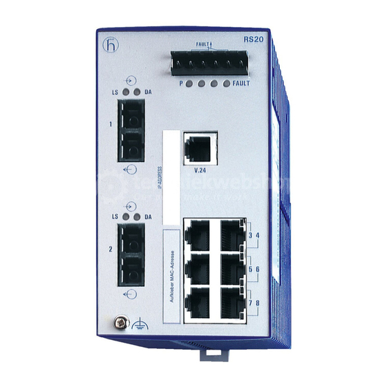
1.1.3 Number of ports and media for RS20-... RS20 FAULT +24V(P1) 0V 0V +24V(P2) FAULT Stand by Stand by V.24 RS20 RS20 FAULT FAULT +24V(P1) 0V 0V +24V(P2) +24V(P1) 0V 0V +24V(P2) FAULT FAULT Stand by Stand by Stand by Stand by V.24 V.24... - Page 30 RS20 FAULT +24V(P1) 0V 0V +24V(P2) FAULT Stand by Stand by V.24 RS20 RS20 FAULT FAULT +24V(P1) 0V 0V +24V(P2) +24V(P1) 0V 0V +24V(P2) FAULT FAULT Stand by Stand by Stand by Stand by V.24 V.24 RS20-0800M2M2...D... RS20-0800T1T1...D... RS20-0800M2T1...D... Figure 2: Device variants with 8 × 10/100 Mbit/s ports (RS20-0800...) 1 to 9 –...
- Page 31 RS20 FAULT +24V(P1) 0V 0V +24V(P2) FAULT Stand by Stand by V.24 RS20 RS20 FAULT FAULT +24V(P1) 0V 0V +24V(P2) +24V(P1) 0V 0V +24V(P2) FAULT FAULT Stand by Stand by Stand by Stand by V.24 V.24 RS20-2400M2M2...D... RS20-2400M2T1...D... RS20-2400T1T1...D... Figure 4: Device variants with 24 × 10/100 Mbit/s ports (RS20-2400...) 1 to 9 –...
-
Page 32: Number Of Ports And Media For Rs30
9 – port 1 + port 2, free choice of connections: MM: Multimode FX, DSC, 100 Mbit/s NN: Multimode FX, ST, 100 Mbit/s VV: Singlemode FX, DSC, 100 Mbit/s UU: Singlemode FX, ST, 100 Mbit/s LL: Singlemode Longhaul FX, DSC, 100 Mbit/s GG: Singlemode Longhaul+ FX, DSC, 100 Mbit/s, 200 km 10 –... - Page 33 RS30 FAULT +24V(P1) 0V 0V +24V(P2) FAULT Stand by Stand by V.24 RS30 RS30 FAULT FAULT +24V(P1) 0V 0V +24V(P2) +24V(P1) 0V 0V +24V(P2) FAULT FAULT Stand by Stand by Stand by Stand by V.24 V.24 RS30-1602T1T1...D... RS30-1602O6O6...D... RS30-1602O6T1...D... Figure 7: Device variants with 2 × 1000 Mbit/s ports and 16 × 10/100 Mbit/s ports (RS30-1602...) 1 to 9 –...
- Page 34 RS30 RS30 RS30 FAULT FAULT FAULT +24V(P1) 0V 0V +24V(P2) +24V(P1) 0V 0V +24V(P2) +24V(P1) 0V 0V +24V(P2) FAULT FAULT FAULT Stand by Stand by Stand by Stand by Stand by Stand by V.24 V.24 V.24 RS30-2402OOZZ...D... RS30-1602OOZZ...D... RS30-0802OOZZ...D... Figure 9: Device variants with 4 uplink ports 1 to 6 –...
-
Page 35: Number Of Ports And Media For Rs40
1.1.5 Number of ports and media for RS40-... RS40 FAULT +24V(P1) 0V 0V +24V(P2) FAULT Stand by Stand by V.24 FAULT RS40 +24V(P1) 0V 0V +24V(P2) FAULT Stand by Stand by V.24 RS40-0009CCCCED... RS40-0009CCCCSD... RS40-0009CCCCTD... Figure 10: Device variants with 9 × 1000 Mbit/s ports (RS40-0009...) 1 to 5 and 8 to 9 –... -
Page 36: Device Variants With Poe (Optional)
Device variants with PoE (optional) 1.2.1 Number of ports and media for devices with PoE FAULT RS22 +48V(P1) 0V 0V +48V(P2) FAULT Stand by Stand by V.24 RS22-1700MMM2...P... Figure 11: RS22 device variants with PoE (example: RS22-1700MMM2...P...) 1 to 5 and 7 to 9 – see figure 5 6 –... - Page 37 RS32 FAULT +48V(P1) 0V 0V +48V(P2) FAULT Stand by Stand by V.24 RS32-0802OOZZ...P... Figure 12: RS32 device variants with 4 uplink ports (example: RS32- 0802OOZZ...P...) 1 to 5 and 7 to 9 – see figure 9 6 – ports in compliance with 10/100BASE-T(X) (RJ45 connections; the PoE-capable ports 7 to 10 are indicated accordingly) Device variants RS22-...
-
Page 38: Poe Power Units
1.2.2 PoE power units The following PoE power units are available for supplying the devices with PoE voltage: RPS90/48V LV: Low-voltage PoE power unit Input voltage range: 24 V DC to 48 V DC Power output at up to +60 °C: 90 W Power output at +60 °C to +70 °C: 60 W ... -
Page 39: 10/100 Mbit/S Twisted Pair Port
100 Mbit/s half-duplex mode, 100 Mbit/s full duplex mode 10 Mbit/s half-duplex mode, 10 Mbit/s full duplex mode Delivery state: Autonegotiation activated The port casing is electrically connected to the front panel. The pin assignment corresponds to MDI-X. Function BI_DB+ BI_DB-... -
Page 40: 10/100 Mbit/S Twisted-Pair Connection Poe (Rs22
1.3.3 10/100 Mbit/s twisted-pair connection PoE (RS22-.../RS32-...) This port is an RJ45 socket. The 10/100 Mbit/s PoE port allows you to connect network components as a PoE voltage sink according to the standard IEEE 802.3 10BASE-T/ 100BASE-TX and IEEE 802.3af. This port supports: ... -
Page 41: 100 Mbit/S F/O Port
For the device variants RS40-..., you have the option of using either Gigabit Ethernet SFP transceivers or Fast Ethernet SFP transceivers at the combo ports. See “Accessories” on page 77. Verify that you connect LH ports only with LH ports, SX ports only with SX ports, and LX ports only with LX ports. -
Page 42: Display Elements
Media type Connection options Twisted pair cable Technical standard IEEE 802.3 10BASE-T/100BASE-TX/ 1000BASE-T Connection type RJ45 Fiber optic cable either Technical standard IEEE 802.3 100BASE-FX Connection type Fast Ethernet SFP transceiver Technical standard IEEE 802.3 1000BASE-SX/LX Connection type 1 Gigabit Ethernet SFP transceiver Table 10: Combo ports: Connection options 10/100/1000 Mbit/s twisted pair port ... - Page 43 P - Power (green/yellow LED) Not glowing Supply voltages P1 and P2 are too low FAULT - detected error, signal contact (red LED) Glowing red The signal contact is open, i.e. it is reporting a detected error. Not glowing The signal contact is closed, i.e. it is not reporting a detected error.
-
Page 44: Management Interfaces
LS - link status (green LED) Not glowing No valid connection Glowing green Valid connection Flashing green (1 time a period) Port is switched to stand-by. Flashing green (3 times a Port is switched off period) DA - data (yellow LED) Not glowing No data reception at corresponding port Flashing yellow... - Page 45 The V.24 interface is not electrically insulated from the supply voltage. RJ11 RJ11 n.c. Figure 16: Pin assignment of the V.24 interface and the DB9 plug Note: The Terminal cable is available as an accessory. Installation RS20/22/30/32/40 Release 07 10/2021...
-
Page 46: Installation
Installation The devices have been developed for practical application in a harsh industrial environment. On delivery, the device is ready for operation. Perform the following steps to install and configure the device: Checking the package contents Installing and grounding the device ... -
Page 47: Checking The Package Contents
Checking the package contents Perform the following work steps: Check whether the package includes all items named in the section “Scope of delivery” on page Check the individual parts for transport damage. Installing and grounding the device WARNING FIRE HAZARD Install the device in a fire enclosure according to IEC 60950-1. -
Page 48: Din Rail Mounting On Ships (Rs30-0802
RS22/RS32 RS20/RS30/RS40 To mount the device onto a horizontally mounted 35 mm DIN rail according to DIN EN 60715, proceed as follows: Slide the upper snap-in guide of the device into the DIN rail. Pull the rail lock slide down using a screwdriver, and press the lower part of the device against the DIN rail. -
Page 49: Mounting On A Vertical Flat Surface
Figure 17: Mounting the RS30-0802... on ships with the Open Rail Mounting Kit 1 - Open Rail Mounting Kit 942 007-001 2 - Open Rail Mounting Kit 942 007-101 2.2.3 Mounting on a vertical flat surface Applies to the device variants RS22 and RS32: You have the option of attaching the device to a vertical flat surface. -
Page 50: Grounding The Device
Mount the device on the wall plate as shown in the illustration. Insert the upper snap-in guide of the device into the rail and press it down against the rail until it snaps into place. Fasten the wall plate (see on page 77 “Accessories”) on a level wall surface using 4 screws. -
Page 51: Installing An Sfp Transceiver (Optional)
Installing an SFP transceiver (optional) Prerequisites: Exclusively use Hirschmann SFP transceivers. See “Accessories” on page 77. Figure 18: Installing SFP transceivers: Installation sequence Perform the following work steps: Take the SFP transceiver out of the transport packaging (1). Remove the protection cap from the SFP transceiver (2). ... -
Page 52: Connecting The Terminal Block
Switch Switch Ring Coupli Redund Coupli Ring Contro Coupl Software Stand-by redun ancy port l port configuratio Position Position dancy switch manager manag port configuration has priority over DIP switch configuration Delivery state: both DIP switches “ON”. Before starting operation of the device, check whether the default settings of the DIP switch correspond to your requirements. -
Page 53: Rs20/Rs30/Rs40: Supply Voltage And Signal Contact
2.5.1 RS20/RS30/RS40: supply voltage and signal contact The supply voltage and the signal contact are connected via a 6-pin terminal block with snap lock. Supply voltage for RS20/RS30/RS40 The supply voltage can be connected redundantly. Both inputs are uncoupled. There is no distributed load. With redundant supply, the power supply unit with the higher output voltage supplies the device on its own. -
Page 54: Rs22/Rs32: Supply Voltage And Signal Contact
The failure of the connection on at least one port. The report of the link status can be masked by the Management for each port. In the delivery state is deactivated. Loss of the ring redundancy reserve. A detected error during the self-test. - Page 55 First connect the protective conductor to the protective conductor terminal. Connect the DC voltage to the 2-pin terminal block. Use a supply cable with a maximum length of 2 m (6.56 ft) to the power unit. RPS90/48V HV: connecting the input voltage ...
- Page 56 RS22/RS32 supply voltage The RPS90/48V LV and RPS90/48V HV PoE power supply units provide an output voltage of typically 48 V DC for supplying the RS22-.../RS32-... devices with PoE voltage. Figure Assignment Supply voltage range Minus terminal of the output voltage Output voltage (PoE voltage) range: Plus terminal of the output voltage...
-
Page 57: Mounting The Terminal Block
A detected error during the self-test. Incorrect configuration of the HIPER-Ring or ring coupling. The following condition is also reported in RM mode: Ring redundancy reserve is available. On delivery, there is no ring redundancy monitoring. Pull the terminal block off the device and connect the power supply and signal lines. -
Page 58: Operating The Device
Operating the device By connecting the supply voltage via the terminal block, you start the operation of the device. Connecting data cables Note the following general recommendations for data cable connections in environments with high electrical interference levels: Keep the length of the data cables as short as possible. ... -
Page 59: Making Basic Settings
Making basic settings WARNING UNINTENTIONAL OPERATION IN DEVICE Install and maintain a process that assigns a unique IP address to every device in the network. Failure to follow this instruction can result in death, serious injury, or equipment damage. The IP parameters must be entered when the device is installed for the first time. -
Page 60: Monitoring The Ambient Air Temperature
Monitoring the ambient air temperature Operate the device below the specified maximum ambient air temperature exclusively. See “Technical data” on page 64. The ambient air temperature is the temperature of the air at a distance of 5 cm (2 in) from the device. It depends on the installation conditions of the device, for example the distance from other devices or other objects, and the output of neighboring devices. -
Page 61: Maintenance And Service
Maintenance and service When designing this device, Hirschmann largely avoided using high-wear parts. The parts subject to wear and tear are dimensioned to last longer than the lifetime of the product when it is operated normally. Operate this device according to the specifications. ... -
Page 62: Disassembly
Disassembly Removing the device WARNING ELECTRIC SHOCK Disconnect the grounding only after disconnecting all other cables. Failure to follow this instruction can result in death, serious injury, or equipment damage. RS20/RS30/RS40 RS22/RS32 Perform the following work steps: Disconnect the data cables. ... -
Page 63: Removing An Sfp Transceiver (Optional)
Removing an SFP transceiver (optional) Figure 23: De-installing SFP transceivers: De-installation sequence Perform the following work steps: Open the locking mechanism of the SFP transceiver (1). Pull the SFP transceiver out of the slot via the open locking mechanism (2). -
Page 64: Technical Data
Technical data General technical data Dimensions W × H × D RS20-0400... 47 mm × 131 mm × 111 mm (1.85 in × 5.16 in × 4.37 in) RS20-08..., RS20-09..., RS30-0802 74 mm × 131 mm × 111 mm (2.91 in ×... - Page 65 Power supply Rated voltage AC: 24 V AC RS20-..., RS30-..., Voltage range AC incl. maximum 18 V AC ... 30 V AC RS40-... tolerances: Rated voltage range DC: 12 V DC ... 24 V DC Voltage range DC incl. maximum 9.6 V DC ...
- Page 66 PoE power unit Rated voltage DC: 24 V DC ... 48 V DC RPS90/48V LV Voltage range DC incl. maximum 18 V DC ... 60 V DC tolerances: Power consumption at 24 V DC 4.20 A Power consumption at 48 V DC 2.10 A Output voltage 48 V DC ...
- Page 67 Operating RS20/RS30/RS40 Standard: 0 °C ... +60 °C (+32 °F ... temperature +140 °F) Extended: -40 °C ... +70 °C (- 40 °F ... +158 °F) RS22-..., RS32-... Standard: 0 °C ... +60 °C (+32 °F ... +140 °F) Extended: -40 °C ...+60 °C (-40 °F to +140 °F) RS40-...B...
- Page 68 Dimension drawings inch 4.17 0.55 1.81 Figure 24: Dimensions of device variants RS20-04... with operating temperature characteristic value S, T and E inch 2.84 4.17 0.55 Figure 25: Dimensions of device variants - RS20-08... and RS20-09... with operating temperature characteristic value S, T and E - RS30-08...
- Page 69 inch 4.33 4.17 0.55 Figure 26: Dimensions of device variants - RS20-16... , RS20-17... and RS20-24... with operating temperature characteristic value S, T and E - RS30-16... and RS30-24... with operating temperature characteristic value S, T and E - RS40-09... with operating temperature characteristic value T and E 3.55 4.53 0.47...
- Page 70 4.53 4.73 0.47 Figure 28: Dimensions of device variants RS22.../RS32... with 16 to 26 ports with operating temperature characteristic value S, T and E 7,05 2.36 4.53 0.28 Figure 29: Dimensions of RPS90/48V LV and RPS90/48V HV PoE power units Installation RS20/22/30/32/40 Release 07 10/2021...
- Page 71 EMC and immunity EMC compliance – IEC/EN 61000-6-2:2005 EMI TYPE tests, test acc. to: IEC/EN 61000-4-2 Electrostatic discharge Contact discharge 4 kV 8 kV 8 kV Air discharge 8 kV 15 kV 15 kV IEC/EN 61000-4-3 Electromagnetic field 80 MHz ... 3000 MHz max.
- Page 72 Product Wave Fiber System Example Fiber code length attenuatio for F/O attenuatio Dispersion M-SFP-... cable length -SX/LC... MM 850 nm 50/125 µm 0 dB ... 0 km ... 3.0 dB/km 400 MHz×km 7.5 dB 0.55 km (0 mi ... 0.34 mi) -SX/LC...
- Page 73 e. Including 2.5 dB system reserve when compliance with the fiber data is observed. Product Wave Wave Fiber System Example Fiber Dispersion code length length attenuat for F/O attenuatio M-SFP- cable BIDI... length Type A SM 1310 nm 1550 nm 9/125 µm 0 dB ... 0 km ...
- Page 74 Product Wave Fiber System Example Fiber BLP/ code length attenuatio for F/O attenuation Dispersion M-FAST- cable SFP-... length -LH/LC... SM 1550 nm 9/125 µm 10 dB ... 47 km ... 0.25 dB/km 19 ps/(nm×km) 29 dB 104 km (29.20 mi .. .
- Page 75 Power consumption/power output Device name Device model Maximum Power output power consumption 2 uplink ports: RS20-0400... 2xTX port 5.3 W 18.1 Btu (IT)/h RS20-0400... 1xFX port, 1xTX port 6.5 W 22.2 Btu (IT)/h RS20-0400... 2xFX port 7.7 W 26.3 Btu (IT)/h RS20-0800...
- Page 76 Device name Device model Maximum Power output power consumption RS22-0800... 2xFX port 73.3 W 40.0 Btu (IT)/h RS22-1600... 2xTX port 75.0 W 45.8 Btu (IT)/h RS22-1600... 1xFX port, 1xTX port 76.2 W 49.9 Btu (IT)/h RS22-1600... 2xFX port 77.4 W 54.0 Btu (IT)/h RS22-2400-...
- Page 77 Accessories Note that products recommended as accessories may have different characteristics to those of the device, which may limit the application range of the overall system. For example, if you add an accessory with IP20 to a device with IP65, the degree of protection of the overall system is reduced to IP20.
- Page 78 Bidirectional Gigabit Ethernet SFP transceiver Certification type Temperature range Order number M-SFP-BIDI Type A LX/LC EEC Standard level 0 °C ...+70 °C (+32 °F ...+158 °F) 943 974-001 M-SFP-BIDI Type B LX/LC EEC Standard level 0 °C ...+70 °C (+32 °F ...+158 °F) 943 974-002 M-SFP-BIDI Type A LH/LC EEC Standard level 0 °C ...+70 °C (+32 °F ...+158 °F) 943 975-001...
- Page 79 Fast Ethernet SFP transceiver Certification type Temperature range Order number SFP-FAST-MM/LC Entry level 0 °C ...+60 °C (+32 °F ...+140 °F) 942 194-001 SFP-FAST-MM/LC EEC Entry level 0 °C ...+70 °C (+32 °F ...+158 °F) 942 194-002 SFP-FAST-SM/LC Entry level 0 °C ...+60 °C (+32 °F ...+140 °F) 942 195-001 SFP-FAST-SM/LC EEC...
- Page 80 Underlying technical standards Name CAN/CSA C22.2 No. 213 Non-incendive Electrical Equipment for Use in Class I, Division 2 Hazardous Locations. EN 50121-4 Railway applications - EMC - emitted interference and interference immunity for signal and telecommunication systems EN 55032 Electromagnetic compatibility of multimedia equipment –...
-
Page 81: A Further Support
You find the addresses of our partners on the Internet at http://www.hirschmann.com. A list of local telephone numbers and email addresses for technical support directly from Hirschmann is available at https://hirschmann-support.belden.com. This site also includes a free of charge knowledge base and a software download section. Customer Innovation Center... - Page 82 Installation RS20/22/30/32/40 Release 07 10/2021...
- Page 83 Installation RS20/22/30/32/40 Release 07 10/2021...
Need help?
Do you have a question about the HIRSCHMANN RS20 and is the answer not in the manual?
Questions and answers
我需要通过snmp获取rs20 rail switch 的cpu 内存信息 需要提供一下对应oid