
Related Manuals for Belden HIRSCHMANN Dragon PTN CSM310-A


Summary of Contents for Belden HIRSCHMANN Dragon PTN CSM310-A
- Page 1 User Manual Installation Dragon PTN Central Switching Module PTN-CSM310-A/PTN-CSM540-A Central Switching Module PTN-CSM310-A/PTN-CSM540-A Technical Support Release 03 05/2020 https://hirschmann-support.belden.eu.com...
- Page 2 The naming of copyrighted trademarks in this manual, even when not specially indicated, should not be taken to mean that these names may be considered as free in the sense of the trademark and tradename protection law and hence that they may be freely used by anyone. ©...
-
Page 3: Table Of Contents
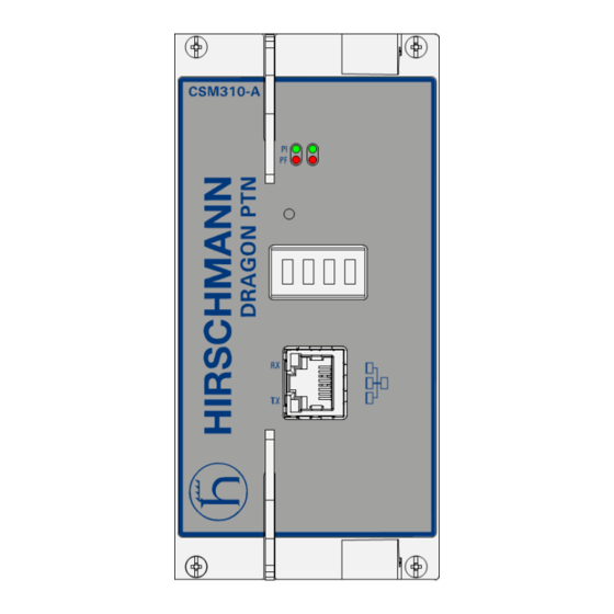
Contents INTRODUCTION ......................5 General ....................5 Manual References ................6 MODULE DESCRIPTION ....................6 Front Panel ..................6 2.1.1 Insert/Remove Module into/from Node ........... 7 2.1.2 LEDs ......................7 2.1.3 Reset Button - Factory Default - Reboot Node .......... 8 2.1.4 Alphanumeric Display ................ - Page 4 List of figures Figure 1 Front Panel CSM310-A In Aggregation Node ..............6 Figure 2 Front Panel CSM540-A In Core Node ................7 Figure 3 HiProvision Management Connector ................13 Figure 4 Dragon PTN Management, Both CSM Types Included, Core, Aggregation ....13 Figure 5 SyncE Clock Recovery ....................
-
Page 5: Introduction
1. INTRODUCTION 1.1 General This document is valid as of Dragon PTN Release 4.3DR. This document describes the CSM310-A/CSM540-A Central Switching module (=CSM), which is the heart of the Dragon PTN nodes. This module provides the main processing within the Dragon PTN nodes via an Integrated Ethernet Multilayer Switch and onboard Traffic Manager. -
Page 6: Manual References
1.2 Manual References Table 2 is an overview of the manuals referred to in this manual. ‘&’ refers to the language code, ‘*’ refers to the manual issue. All these manuals can be found in the HiProvision (=Dragon PTN Management System) Help function. Table 2 Manual References Ref. -
Page 7: Insert/Remove Module Into/From Node
Hidden Reset LEDs Display active/standby LED Button Socket Head HiProvision Management Cap Screw Connector HiProvision PC Figure 2 Front Panel CSM540-A In Core Node 2.1.1 Insert/Remove Module into/from Node See ‘Dragon PTN Installation and Operation Manual’ Ref.[1] in Table 2. CAUTION: 1) Do not touch the heat sink when the CSM is in operation, or when removing the CSM from the node. -
Page 8: Reset Button - Factory Default - Reboot Node
Table 4 LED Indications in Normal Operation Color Status PI (=Power Input) Not lit, dark +12V power input to the board not OK Green +12V power input to the board OK PF (=Power Failure) Not lit, dark power generation on the board itself is OK power generation on the board itself is erroneous FLT (=FauLT) Not lit, dark... -
Page 9: Alphanumeric Display
...in any other way than described above is not relevant because the CSM that remains active keeps the current configuration and will overwrite the default configuration of the reset CSM immediately after it has rebooted. During the (re)boot of a CSM, its LEDs (see §2.1.2) and display (see §2.1.4) will follow a boot-cycle. -
Page 10: Table 6 Csm Display: Normal Operation
b. During Normal Operation Table 6 CSM Display: Normal Operation Display Description <Redundancy State> Indicates the redundancy (=RDST) state of the CSM. In case of a single CSM (or non- redundant CSM), the value will always be RDST ACT. Possible values with redundant CSMs: - RDST ACT: Indicates the active CSM. -
Page 11: Table 7 Csm Display: Error List
Table 7 CSM Display: Error List Display Description Curative Action AMBIENT TEMP OUT Indicates that the measured node temperature Verify the ambient temperature, cooling in the OF BOUND (=ambient temperature) is not in the range room. (only CSM540-A) [-20 °C … + 55 °C] or [-4 °F … 133 °F]. CBLF S<x>... -
Page 12: Hiprovision Management Port/Channel
Display Description Curative Action NODENUMBER Indicates a mismatch between the configured node Make sure that both node numbers on the MISMATCH number on the NSM and HiProvision. NSM and HiProvision match. NSM backplane type invalid Probably the NSM is defect. Replace the NSM. BACKPLANETYPE INVALID NSM backplane type mismatch. -
Page 13: Figure 3 Hiprovision Management Connector
NOTE: The management port can be disabled via HiProvision for security reasons, see Ref. [2Mgt] in Table 2. The management port is by default up. Table 8 RJ45 HiProvision Management Connector: Pin Assignments Pin No. Signal 100/100Base-T Signal 1000Base-T Transmit output (+) Transmit output (-) Receive input (+) Receive input (-) -
Page 14: Functional Operation
b. HiProvision - CSM Connection Scenarios There are multiple connection scenarios possible between the HiProvision PC and the CSM (or Dragon PTN network). Direct connection; Connection via switch, router; Connection with CSM Redundancy; Connection with HiProvision Redundancy; Connection with Entry Point Redundancy. Depending on the connection scenario, the configuration differs and IP addresses must be configured in different places. -
Page 15: Central Node Switching
2.2.3 Central Node Switching The switch on the CSM is non-blocking and has following data bus: CSM310-A: 4 x '1 Gbps / 10 Gbps' ports 24 x '1 Gbps' ports CSM540-A: 60 x '1 Gbps / 10 Gbps' ports Which node slot supports which speeds and bandwidths is described in the ‘Dragon PTN Bandwidth Overview’... -
Page 16: Figure 5 Synce Clock Recovery
The CSM cleans up and redistributes this clock over the entire node to all the interface slots. If multiple recovered clocks are available in a node, the CSM will select the best available clock. SyncE Support: Verify the ‘PROTOCOL AND FEATURE SUPPORT MATRIX’ in Ref. [2Net] in Table 2 to find out which IFMs support this feature;... -
Page 17: Layer2: Link Aggregation/Lag (=Link Aggregation Group) On Csm310-A17
b. (=Precision Time Protocol) The Precision Time PTP IEEE 1588v2 Protocol (=PTP), as defined in IEEE 1588v2, is a protocol that manages the distribution of a synchronous timestamp clock (micro-second accuracy), network wide between an external grandmaster clock and its slaves or substations. The CSM verifies that all the IFMs in the node have the same node-internal timestamp. -
Page 18: Self-Test
The resulting combined logical link: has at least the bandwidth of one individual link (1 Gbps bandwidth for a 1G port, 10 Gbps for a 10G port), but can have more bandwidth if both conditions below are met: multiple streams from different MAC addresses are streamed over the LAG; the LAG algorithm loadshares these streams over different links within the LAG;... -
Page 19: Health Monitor
2.2.9 Health Monitor If you have problems with a specific node, a service in a node, responsiveness of a node, possible traffic loss is a node, it is always a good idea to verifiy the Health Monitor in HiProvision (See also Ref. [2Net] in Table 2). This monitor shows more info on the CSM(s) usage in a node: CPU usage;... -
Page 20: Heat Sink
Heat Sink Heat Sink Heat Sink Management Hidden Reset Display Connector Button Figure 9 CSM540-A: Top View Bottom Side: Micro SD Card Interface Figure 10 CSM540-A: Bottom View (Including Micro SD Card) 2.3.1 Heat Sink A heat sink is required for the natural cooling of the CSM module. A heat sink can reach a high temperature during operation. -
Page 21: Straps
2.3.2 Straps No user relevant straps. 2.3.3 DIP Switches The CSM has no user relevant DIP switches. 2.3.4 CSM Replacement / Micro SD Memory Card The SD card location can be found in the pictures in §2.3. The SD card has two purposes: Allow the easy and fast replacement of a broken CSM in the live network without further HiProvision interaction. -
Page 22: Csm Redundancy
NOTE: This SD card is neither required nor essential for the CSM to operate, but it makes a possible CSM replacement in the future a lot easier and faster. NOTE: If the reset button has been pushed at least for seven seconds (see §2.1.3), the latest configuration on the SD card will be replaced with the factory default settings. -
Page 23: Revertive/Non-Revertive Behavior
NOTE: With CSM redundancy, a switchover is only possible when both CSMs have the same firmware version and one CSM is 'active' and the other CSM is 'standby'. When a switchover occurs, the connections or services going through that node will be interrupted shortly. -
Page 24: Add A New Node To A Live Network
both CSMs must be in synchronization. It means that one CSM must be in the Active state, and the other one in the Standby state. How to perform such an upgrade procedure has been described in Ref. [2Mgt] in Table 2. NOTE: ‘In Service Revert’... - Page 25 Central Switching Module Data Communication Network Electromagnetic Compatibility Electromagnetic Interference Ethernet Ring Protection Fault I²C I-Squared-C / Inter Integrated Circuit International Electrotechnical Commission IEEE Institute of Electrical and Electronics Engineers IETF Internet Engineering Task Force InterFace Module International Telecommunication Union Link Aggregation Group Light Emitting Diode Low Voltage Directive...
Need help?
Do you have a question about the HIRSCHMANN Dragon PTN CSM310-A and is the answer not in the manual?
Questions and answers