Table of Contents
Advertisement
Quick Links
INSTRUCTIONS-PARTS LIST
This manual contains IMPORTANT
WARNINGS AND INSTRUCTIONS
READ AND RETAIN FOR REFERENCE
P
RECISION
PROPORTIONING CONTROLLER
FOR PROPORTIONAL MIXING OF PLURAL COMPONENT COATINGS
Model 231-119, for Air Spray Systems
120 psi (8.4 bar) MAXIMUM FLUID WORKING PRESSURE
100 psi (7 bar) MAXIMUM AIR INPUT PRESSURE
FOR USE ONLY IN ORDINARY LOCATIONS.
DO NOT OPERATE IN HAZARDOUS LOCATIONS,
AS DEFINED IN ARTICLE 500 OF THE
NATIONAL ELECTRICAL CODE (USA).
TABLE OF CONTENTS
. . . . . . . . . . . . . . . . . . . . . . . . . . . .
. . . . . . . . . . . . . . . . . . . . . . . . . .
. . . . . . . . . . . . . . . . . . . . . . . . . .
. . . . . . . . . . . . . . . . . . . . . . . . . . . . . . .
. . . . . . . . . . . . . . . . . . . . . . . . . . . . .
. . . . . . . . . . . . . . . . . . . . . . . . . . . . . .
. . . . . . . . . . . . . . . . . . . . . . . . . . . . . .
. . . . . . . . . . . . . . . . . . . . . . . . .
. . . . . . . . . . . . . . . . .
. . . . . . . . . . . . . . . . . . . . . . . . . . . . .
. . . . . . . . . . . . . . . . . . . . . . .
Parts Drawings and Lists
. . . . . . . . . . . . . . . . . . . . . . .
. . . . . . . . . . . . . . . . . . . . . . .
. . . . . . . . . . . . . . . . . . . . . . . . .
. . . . . . . . . . . . . . . . . . .
. . . . . . . . . . . . . . . . . . . . . . . . . . .
. . . . . . . . . . . . . . . . . . . . .
. . . . . . . . . . . . . . . . . . . .
. . . . . . . . . . . . . . . . . . . . . . . . . . . . . .
. . . . . . . . . . . . . . . . . . . . . .
. . . . . . . . . . . . . . . . . . . . . . . . . . . .
. . . . . . . . . . . . . . . . . . . . . . . . .
Graco Phone Numbers
. . . . . . . . . . . . .
Hazard of Using Fluids Containing Halogenated Hydrocarbons
Never use 1,1,1-trichloroethane, methylene chloride, other halogenated hydrocarbon solvents or fluids containing
such solvents in this equipment. Such use could result in a serious chemical reaction, with the possibility of explosion,
which could cause death, serious bodily injury and/or substantial property damage.
Consult your fluid suppliers to ensure that the fluids used are compatible with aluminum and zinc parts.
GRACO INC. P.O. BOX 1441 MINNEAPOLIS, MN 55440-1441
M
IX
2
3
. . . . . . . . . . . . . . .
3-5
6
7, 8
. . . . . . . . . .
9, 10
11-13
14
15, 16
17
18, 19
20
21
22, 23
24
25
26, 27
28
. . . . . . . . . . . . .
29
30
31
. . . . . . . . . . . . . . . . .
32
33
34
35
Back Cover
Back Cover
COPYRIGHT 1991, GRACO INC.
WARNING
308-074
Rev A
Advertisement
Table of Contents

Related Manuals for Graco PRECISIONMIX 231-119


Summary of Contents for Graco PRECISIONMIX 231-119
-
Page 1: Table Of Contents
Consult your fluid suppliers to ensure that the fluids used are compatible with aluminum and zinc parts. GRACO INC. P.O. BOX 1441 MINNEAPOLIS, MN 55440–1441 COPYRIGHT 1991, GRACO INC. -
Page 2: Safety Warnings
SAFETY WARNINGS SERIOUS BODILY INJURY, EXPLOSION, FIRE, OR ELECTRIC SHOCK CAN OCCUR IF THE PRECAUTIONS BELOW ARE NOT FOLLOWED. ELECTRICAL EQUIPMENT SHALL ONLY BE INSTALLED, OPERATED, AND SERVICED BY TRAINED, QUALIFIED PERSONNEL WHO SHALL BE FULLY CONVERSANT WITH THE REQUIREMENTS STATED WITHIN THIS INSTRUCTION MANUAL. READ AND UNDERSTAND ALL INSTRUCTION MANUALS AND WARNING LABELS BEFORE OPERATING THE EQUIPMENT. -
Page 3: Definition Of Terms
HOW THE P WORKS RECISION The standard Graco PrecisionMix can blend all popular 12 and 13), and presses the START button on the control two-component epoxy or polyurethane paints. For infor- panel. From that point on, normal operation of the Preci- mation on handling abrasive fluids, contact your Graco sionMix is controlled by the operation of the spray gun. - Page 4 When the spray gun is triggered, the two components are Whenever the fluid overrun is greater than the TOLER- introduced into the integrator chamber one at a time (see ANCE setting, an indicator on the control panel flashes Fig. 2). Their entry into the chamber is controlled by a and the system stops.
- Page 5 FUNCTIONAL DIAGRAM – COMPONENT A (RESIN) DISPENSE COMPONENT A COMPONENT B VALVE VALVE SOLVENT PURGE PURGE COMPONENT A COMPONENT INLET INLET FILTER CHECK VALVE SHUT–OFF VALVE INTEGRATOR VOLUME COUNTER RATIO CHECK VALVE STATIC MIXER GUN SUPPLY FUNCTIONAL DIAGRAM – COMPONENT B (CATALYST) DISPENSE COMPONENT A COMPONENT B VALVE...
-
Page 6: Typical Installation
Supply Tank, Component A IMPORTANT: Fluid Hose Supply Tank, Component B Failure to limit air supply to 100 Air Hose psi (7 bar) will void the Graco Supply Tank, Solvent warranty. Main Power Switch Fluid Shutoff Valve Failure to ensure that the air... -
Page 7: Installation
Take note of any evidence of rough handling during shipment. Immediately report any dam- INTEGRATOR age to the carrier’s claims agent, and also notify Graco Customer Service (Tel. 708–671–8400). If you find any damage, do not continue unpacking until the PrecisionMix and shipping material have been in- spected by the claims agent. - Page 8 PrecisionMix. Connect base (color) to page 33. the left filter inlet, and catalyst to the right filter inlet. Graco recommends that the electrical service to this equipment be permanently installed in conduit. Connect fluid hose between the solvent supply tank and the inlet on top of the solvent flush valve.
-
Page 9: Operator Controls And Indicators
OPERATOR CONTROLS AND INDICATORS CONTROL PANEL (Fig. 6) START Button This switch starts PrecisionMix operation. ON/OFF Switch This switch turns the PrecisionMix power on and off. An external contactor can be connected to terminals on the rear of the control box to accomplish this function. Fuse Indicators The three indicators light when the ON/OFF switch is STOP Button... - Page 10 CONTROL BOX (Fig. 7) MIXING ASSEMBLY (Fig. 7) Dispense Valve Knobs Control Panel Cover Lock These knobs adjust the corresponding (A or B) dispense valve opening, to limit the maximum fluid flow rate into the This lock secures the control panel cover, to prevent tam- mixing block.
-
Page 11: Operation
OPERATION The following instructions generally presume a standard 3. Close the tank lids. system using pressure supply tanks for the paint compo- 4. Turn on the air supply and recharge the tanks with air. nents and solvent, and air spray guns. See also “Option- Adjust their air pressure to: al System Arrangements”... - Page 12 11. Begin production. These settings don’t always add up to 200 counts, NOTE: For other color change options, contact your because they have been adjusted for slightly greater Graco representative. precision than the above procedure provides.
- Page 13 8. Flush the ratio check valves as follows: a. Turn OFF the ON/OFF switch. Starting SETPOINT Selector Settings[*] b. Place a fluid cup under the ratio check valves. c. Press the yellow SOLVENT pushbutton until RATIO COMP. A COMP. B clear solvent flows through the catalyst ratio check valve hose.
-
Page 14: Maintenance
(repair kits are avail- able from Graco). Be sure the packing retainers are snug on the dis- pense valves and the air and solvent flush valves. -
Page 15: Service
SERVICE To remove just the top (air) section of the valve: Tools Needed for Disassembly Refer to Fig. 8. Set of open-end wrenches Set of metric hex key wrenches 1. Disconnect the two air line connectors. 2. Unscrew the adjusting screw far enough for the valve Various retaining ring pliers cap screws (B) to clear it. - Page 16 Disassembling the Flush Valves Disassembling the Volume Counters WARNING WARNING To reduce the risk of electric shock, splashing fluid in To reduce the risk of electric shock, splashing fluid in the eyes or on the skin, or other serious injury, AL- the eyes or on the skin, or other serious injury, AL- WAYS follow the Pressure Relief Procedure on WAYS follow the Pressure Relief Procedure on...
-
Page 17: Diagnostics Chart
DIAGNOSTICS CHART WARNING Installing and servicing this equipment requires access to parts which may cause electric shock or other serious bodily injury if the work is not performed properly. Do not install or service this equip- ment unless you are trained and qualified. Always disconnect power to the PrecisionMix before cleaning or servicing. -
Page 18: Troubleshooting Chart
TROUBLESHOOTING CHART PROBLEM CAUSE SOLUTION System won’t run. No power. Turn ON/OFF switch ON. Be sure main electrical disconnect switch is closed. Check fuses. System aborted, and: Overrun indicator flashing on Push STOP, then START. If prob- either channel. lem reoccurs: set tolerance one digit higher;... - Page 19 TROUBLESHOOTING CHART (CONT.) PROBLEM CAUSE SOLUTION No material flow (or Dispense valves closed too far. Open valve knobs further (counter- not enough). clockwise). Fluid shut-off valves closed too far. Turn shut-off knobs all the way coun- terclockwise. Volume counter overrun. Reduce the fluid flow by turning Flashing red LED the dispense valve knobs clockwise...
-
Page 20: Air Schematic
AIR SCHEMATIC Remote Flush Control Part No. 948–596 Air Flush Valve Pushbutton Solvent Flush Valve Solvent Pushbutton Solvent Shuttle Valve Air Shuttle Valve Purge Interlock Dispense Valve A Component A Dispense Valve B Component B Filter ON/OFF Valve Air Supply Flow Switch Regulator... -
Page 21: Electrical Schematic
ELECTRICAL SCHEMATIC... -
Page 22: Precisionmix
PARTS LIST PrecisionMix PART DESCRIPTION PART DESCRIPTION (REF) PROPORTIONER ... . . 223-861 COUNTER ASSEMBLY, volume 156-849 NIPPLE; 3/8 npt ....0.1 cc/tooth (see page 24) . - Page 23 PARTS DRAWING PrecisionMix 10, 5, 11, 15 (Air Valve); 10, 12, 13 (Solvent Valve) 8, 9...
-
Page 24: Volume Counters
PARTS LIST Volume Counter, 0.1 cc/tooth Volume Counter, 1.6 cc/tooth (Part No. 223-861) (Part No. 223-866) PART DESCRIPTION PART DESCRIPTION 111-062* O-RING ..... . 111-078* O-RING . -
Page 25: Mixer Manifold
Refer to “How to Order Parts” on page 26. MIXER MANIFOLD: 223-859 Mixer Manifold Assembly also includes dispense & flush valves (see separate illustrations). 9A** 9, 9C* NOTE: Wetted-part o-rings are made of EPDM – use only the indicated Graco parts or their equivalent. - Page 26 ....HOW TO ORDER REPLACEMENT PARTS 1. Order all parts from your nearest Graco distributor. 2. Check the parts list to identify the correct part num- ber;...
-
Page 27: Dispense Valves
PARTS DRAWING DISPENSE VALVES: 224-063 LIPS FACE DOWN LIPS FACE DOWN... -
Page 28: Flush Valves
PARTS DRAWING AND LIST Flush Valves (Part No. 224-064) PART DESCRIPTION REF PART DESCRIPTION NO. NO. 111-132 ROD, piston ....111-119 SCREW ..... . . 111-133 PISTON . -
Page 29: Static Mixer Tube Assembly
PARTS DRAWING AND LIST Static Mixer Tube Assembly PART DESCRIPTION PART DESCRIPTION 513-248 WASHER ....513-247 BRACKET, vertical ... . 513-253 WASHER, lock . -
Page 30: Air Panel Assembly
PARTS DRAWING AND LIST Air Panel Assembly (Part No. 948-559) PART DESCRIPTION PART DESCRIPTION 597-605 REGULATOR, air; 0 - 125 psi 502-721 CONNECTOR, 90 ; 1/4” tube 512-900 NUT; 1/2” x 1/4 npt (m) 502-719 CONNECTOR; brass, 1/4” tube 217-074 FILTER, air 595-078 GAUGE;... -
Page 31: Pneumatic Package
PARTS DRAWING AND LIST Pneumatic Package PART DESCRIPTION PART DESCRIPTION 513-227 REDUCER, tube; 1/2” OD 513-052 FLOW SWITCH ....tube x 3/8” OD tube ... 513-218 MANIFOLD, solenoid mounting 513-228 REDUCER, tube;... -
Page 32: Control Panel Assembly
PARTS DRAWING AND LIST Control Panel Assembly (Part No. 223-876) PART DESCRIPTION 111-356 FUSE, 1-amp ....111-363 FUSEHOLDER ....111-357 FUSE, 2-amp . -
Page 33: Accessories
ACCESSORIES USE GENUINE GRACO PARTS AND ACCESSORIES Must be purchased separately . GROUNDING CLAMP 103–538 BLEED–TYPE MASTER AIR VALVE 107–141 GROUND WIRE 208–950 (Required) (Required) 300 psi (21 bar) MAXIMUM WORKING PRESSURE 25 ft (7.6 m) long, Relieves air trapped in the air line between the pump air 12 gauge (1.5 mm ) -
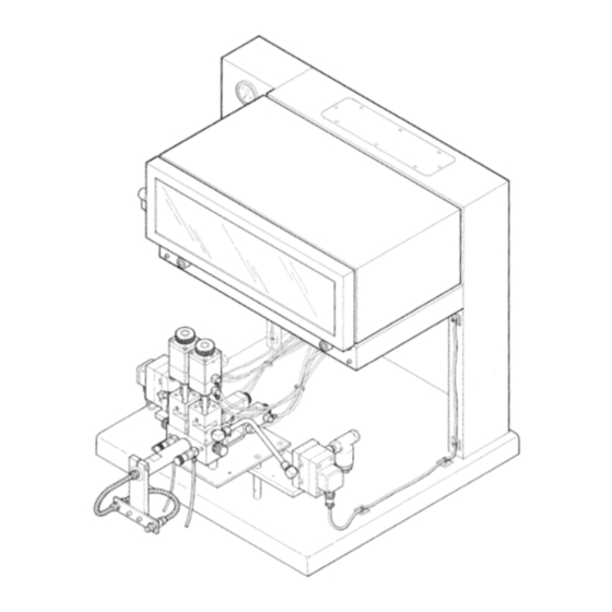
Page 34: Dimensional Drawing
DIMENSIONAL DRAWING 26 in. (660.4 mm) 35 in. (889 mm) 28 in. (711.2 mm) 25 in. (635 mm) 34 in. (863.6 mm) -
Page 35: Technical Data
....... . . 67 to 80 psi (5 to 6 bar). Graco warranty will be voided if air supply exceeds 100 psi (7 bar). -
Page 36: Warranty
Graco distributor to the original purchaser for use. As purchaser’s sole remedy for breach of this warranty, Graco will, for a period of twelve months from the date of sale, repair or replace any part of the equipment proven defective.
Need help?
Do you have a question about the PRECISIONMIX 231-119 and is the answer not in the manual?
Questions and answers