
Subscribe to Our Youtube Channel
Related Manuals for Kontron KBox A-151-EKL


Summary of Contents for Kontron KBox A-151-EKL
- Page 1 USER GUIDE KBox A-151-EKL User Guide Rev. 1.0 Doc. ID: 1070-4126 www.kontron.com // 1...
- Page 2 KBox A-151-EKL - User Guide Rev. 1.0 This page has been intentionally left blank www.kontron.com // 2...
- Page 3 Kontron with respect to technical processes described in the user guide or any product characteristics set out in the user guide. Kontron assumes no responsibility or liability for the use of the described product(s), conveys no license or title under any patent, copyright or mask work rights to these products and makes no representations or warranties that these products are free from patent, copyright or mask work right infringement unless otherwise specified.
- Page 4 ENVIRONMENTAL DAMAGE (COLLECTIVELY, “HIGH RISK APPLICATIONS”). You understand and agree that your use of Kontron devices as a component in High Risk Applications is entirely at your risk. To minimize the risks associated with your products and applications, you should provide adequate design and operating safeguards.
- Page 5 If you have any difficulties using this user guide, discover an error, or just want to provide some feedback, contact Kontron support. Detail any errors you find. We will correct the errors or problems as soon as possible and post the revised user guide on our website.
-
Page 6: Symbols
KBox A-151-EKL - User Guide Rev. 1.0 Symbols The following symbols may be used in this user guide DANGER indicates a hazardous situation which, if not avoided, will result in death or serious injury. WARNING indicates a hazardous situation which, if not avoided, could result in death or serious injury. -
Page 7: For Your Safety
Therefore, in the interest of your own safety and of the correct operation of your new Kontron product, you are requested to conform with the following guidelines. -
Page 8: Lithium Battery Precautions
General Instructions on Usage In order to maintain Kontron’s product warranty, this product must not be altered or modified in any way. Changes or modifications to the product, that are not explicitly approved by Kontron and described in this user guide or received from Kontron Support as a special handling instruction, will void your warranty. -
Page 9: Table Of Contents
KBox A-151-EKL - User Guide Rev. 1.0 Table of Contents Symbols ..........................................6 For Your Safety ........................................7 High Voltage Safety Instructions .................................. 7 Special Handling and Unpacking Instruction ............................7 Lithium Battery Precautions ..................................8 General Instructions on Usage ..................................8 Quality and Environmental Management .............................. - Page 10 KBox A-151-EKL - User Guide Rev. 1.0 5.4. System Expansion I/O Door ................................. 32 5.4.1. Audio Line-out (option) ..................................32 5.4.2. Dual CAN Bus (option) ..................................32 5.4.3. Dual LAN (option) ....................................32 5.4.4. Dual RS232 Serial Ports (option) ..............................32 5.4.5.
-
Page 11: List Of Tables
KBox A-151-EKL - User Guide Rev. 1.0 11.6. Mechanical Specification ..................................64 11.7. Compliance ....................................... 65 Connectors and LEDs ..................................67 12.1. Front Panel Connector Pin Assignments ............................67 12.1.1. Power IN Connector (X101) ................................67 12.1.2. LAN Connectors (X102, X103) ................................67 12.1.3. -
Page 12: List Of Figures
KBox A-151-EKL - User Guide Rev. 1.0 Table 5: Storage Expansion Options ................................. 30 Table 6: Wireless Expansion Options ................................ 31 Table 7: GPIO Input and Output Channels ..............................33 Table 8: Maximum Processor Temperatures ............................36 Table 9: Navigation Hot Keys Available in the Legend Bar ........................ 47 Table 10: Advanced Setup Menu Sub-screens and FunctionsPower Setup Menu .............. - Page 13 Figure 22: Security Setup Menu Example ..............................56 Figure 23: Save and Exit Setup Menu Example............................58 Figure 24: Block Diagram KBox A-151-EKL .............................. 59 Figure 25: Mechanical Dimensions (mm) ..............................64 Figure 26: RP-SMA Standard Connector and Antenna ......................... 71 Figure 27: M.2 Key E 2330 Socket ................................
-
Page 14: 1/ Introduction
New users are recommended to study the instructions within this user guide before switching on the product. The KBox A-151-EKL is a flexible fanless industrial grade DIN Rail embedded box PC designed for use in performance demanding applications requiring flexible DIN Rail mounting in limited space, 24/7 continuous operation and longtime industrial employment. - Page 15 Metal chassis with heatsink Fanless passive cooling Power Power IN 24 VDC (10 VDC to 30 VDC) To ensure you have the latest version of this user guide, visit Kontron’s Embedded Box PC, KBox A-151-EKL website. www.kontron.com // 15...
-
Page 16: 2/ General Safety Instructions
Only connect the product to an external power supply providing the voltage type (AC or DC) and the input power (max. current) specified on the Kontron Product Label and meeting the requirements of the Limited Power Source (LPS) and Power Source (PS2) of UL/IEC 62368-1 . -
Page 17: Instructions Générales De Sécurité
Le non-respect des consignes de sécurité générales suivantes peut entraîner des blessures pour l'utilisateur et/ou des dommages pour le produit. En cas de non-respect des consignes, Kontron Europe est exonéré de la responsabilité en cas d'accident, ceci s'applique également pendant la période de garantie. -
Page 18: Electrostatic Discharge (Esd) Precautions
KBox A-151-EKL - User Guide Rev. 1.0 le produit présente des dommages visibles ou le produit ne fonctionne plus. Dans ce cas, le produit doit être éteint et il faut s'assurer que le produit ne puisse plus être utilisé. -
Page 19: Instructions For The Lithium Battery
2.4. Instructions for the Lithium Battery The product is equipped with a Kontron specific lithium battery BR2032 with cable and is not designed to operate without a lithium battery. If the lithium battery is empty or disconnected, the BIOS settings will be set to the factory defaults. -
Page 20: 3/ Shipment And Unpacking
KBox A-151-EKL - User Guide Rev. 1.0 3/ Shipment and Unpacking 3.1. Packaging The KBox A-151-EKL is packaged together with all parts, in a product specific cardboard package designed to provide adequate protection and absorb shock. 3.2. Unpacking To unpack the product perform the following: Remove packaging. -
Page 21: Product Identification Type Label
Book mount bracket and two M4x6 Torx screws to mount the bracket on the rear side 3.5. Product Identification Type Label The KBox A-151-EKL is part of Kontron’s DIN Rail embedded Box PC. Kontron’s A-Series is intended for control cabinet applications. Table 3: Product Identification... -
Page 22: 4/ Product Features
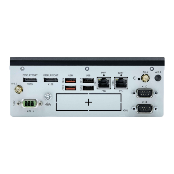
KBox A-151-EKL - User Guide Rev. 1.0 4/ Product Features 4.1. Front Panel The front panel features all the I/O interfaces, status LEDs and the power connection. Figure 3: Front Panel Display port (X109) Antenna (ANT.3) Display port (X108) 10 Serial port (X110) USB 3.2 Gen 2 ports 2 and 1... -
Page 23: Functional Earth Bolt
KBox A-151-EKL - User Guide Rev. 1.0 4.1.3. Functional Earth Bolt The functional earth bolt connects to the chassis ground. 4.1.4. Power LED and State LED The Power LED and State LED indicate the product’s power and state. Table 4: Power LED and State LED Description... -
Page 24: Serial Ports (X111, X110)
KBox A-151-EKL - User Guide Rev. 1.0 4.1.9. Serial Ports (X111, X110) The two serial ports (X111) and (X110) are RS232/422/485 configurable in the BIOS setup menu. For the pin assignment of the serial ports, see Chapter 12.1.6: Serial Port Connectors (X111, X110). -
Page 25: Rear Side
KBox A-151-EKL - User Guide Rev. 1.0 4.2. Rear Side The rear panel features two-threaded openings used to mount a DIN Rail clamp or book mount bracket. Figure 4: Rear Side Three screws securing the DIN Rail clamp Heatsink–Front panel assembly. -
Page 26: Top Side
KBox A-151-EKL - User Guide Rev. 1.0 4.4. Top Side The top side features a heatsink. Figure 6: Top Side Hot Surface Heatsinks can get very hot. To avoid burns and personal injury: • Do not touch the heatsink when the product is in operation •... -
Page 27: Internal Features
KBox A-151-EKL - User Guide Rev. 1.0 4.6. Internal Features This chapter describes internal features relevant to the operation of the product. Figure 8: Internal Components Example 12 VDC power board Optional: I/O door implementation DIMMS (not visible positioned under... -
Page 28: Sbc On-Board Components
KBox A-151-EKL - User Guide Rev. 1.0 4.6.1. 3.5” SBC On-board Components Figure 9: Top Side On-board Components +12 V DC power input header 11 Audio Input/Output Header M.2 Key B 2242/2280 socket (no SATA) 12 Right channel audio AMP output header M.2 Key E 2230 socket... -
Page 29: Figure 10: Bottom Side On-Board Components
KBox A-151-EKL - User Guide Rev. 1.0 Figure 10: Bottom Side On-board Components Serial Port RS232/422/485 (COM2) M.2 Key M 2280 Slot (SATA only) Serial port RS232/422/485 (COM1) CAN Bus 0 CAN Bus 1 For more information regarding the 3.5” SBC’s on-board connectors, headers and jumpers, visit https://www.kontron.com/de/produkte/3.5--sbc-ekl/p162920. -
Page 30: 5/ System Expansion
The KBox A-151-EKL expansion options are factory installed and are not accessible in the field, the product must always be returned to Kontron to replace or install the expansion options described in this chapter. To return the product to Kontron, see Chapter 15.1: Returning Defective Merchandise. -
Page 31: Wireless Expansion Options
The wireless expansion options M.2 Key E (Wi-Fi) and M.2 Key B (LTE (4G) or 5G) modules are factory installed. The module(s) are not accessible in the field, the product must always be returned to Kontron for replacement or installation. -
Page 32: System Expansion I/O Door
KBox A-151-EKL - User Guide Rev. 1.0 5.4. System Expansion I/O Door The system expansion I/O door supports one of the factory installed I/O expansion options. 5.4.1. Audio Line-out (option) The audio line-out expansion option supports one Jack connector for use with a 3.5 mm stereo audio jack to enable the connection of external active speakers and headphones, or other output devices. -
Page 33: 8-Channel Gpio/Dio (Option)
KBox A-151-EKL - User Guide Rev. 1.0 The EthererCAT RJ45 connectors may only be used for LAN. Use for telecommunications is not possible. Prerequisite: Motherboards M.2 2280 B socket is not populated with a different M.2 module. 5.4.6. 8-Channel GPIO/DIO (option) The expansion slot option supports eight GPIO bi-directional digital IO signals, where each GPIO can be selected as an output or an input channel. -
Page 34: Dual Lan And Dual Dp (Option)
KBox A-151-EKL - User Guide Rev. 1.0 Figure 12: Input Application Connected to GPIO 5.4.7. Dual LAN and Dual DP (option) The dual LAN and dual DP expansion option supports two 2.5 GbE RJ45 LAN ports with speed and activity indication LEDs and two DP ports. -
Page 35: 6/ Thermal Management
KBox A-151-EKL - User Guide Rev. 1.0 6/ Thermal Management 6.1. Passive Cooling The KBox A-151-EKL is passively cooled and fanless, using a heatsink. The critical internal components are directly connected to the outer chassis for optimized heat transfer. 6.2. Heatsink The heatsink (180 mm x 123 mm) is located on the top side. -
Page 36: Third Party Components
KBox A-151-EKL - User Guide Rev. 1.0 6.5. Third Party Components When extended and configured with additional third party components, users must take into account that the air temperature inside the product is higher than the ambient temperature. An approximate internal temperature rise occurs. -
Page 37: 7/ Assembly
7/ Assembly 7.1. Before Assembling The KBox A-151-EKL is factory configured to meet customer requirements and then sealed with a protection label. No customer assembly of M.2 expansion slots is required before operation. The M.2 expansion slots are not accessible in the field, the product must always be returned to Kontron to replace the M.2 module(s). - Page 38 KBox A-151-EKL - User Guide Rev. 1.0 The internal 3.5” SBC contains components on both sides that can easily be damaged if handled without reasonable care, resulting in malfunction or no function at all. ESD Sensitive Follow the safety instructions for components that are sensitive to electrostatic discharge (ESD).
-
Page 39: Removing Or Installing A M.2 Module
The factory installed M.2 modules (SSD, Wi-Fi/Bluetooth, LTE and 5G) are not accessible in the field, the product must always be returned to Kontron to replace the module(s), see Chapter 15.1: Returning Defective Merchandise. Wi-Fi/Bluetooth, LTE and 5G operation is only supported with an intact cool adapter. -
Page 40: 8/ Installation
8/ Installation 8.1. Before Installing Before installing the KBox A-151-EKL in the operating environment, ensure that the operating environment meets the specification stated within this user guide, and that there is sufficient access to the Power IN connector and the front panel I/O connectors. -
Page 41: Book Mount Bracket
KBox A-151-EKL - User Guide Rev. 1.0 8.3. Book Mount Bracket To install the product on a flat mounting surface, fix the book mount bracket on the rear side or bottom side, see Table 2: Accessories. Figure 14: Book Mount Bracket... -
Page 42: Clearance
Mount on a surface with a minimum thickness of 3 mm and made of aluminum or better. 8.4. Clearance For sufficient air circulation around the product, Kontron recommends users not to mount or operate any other devices within the specified keep out areas around the product. The specified keep out areas for the product are displayed in Figure 15: Keep Out Areas- Horizontal and Figure 16: Keep Out Areas- Vertical. -
Page 43: Figure 16: Keep Out Areas- Vertical
KBox A-151-EKL - User Guide Rev. 1.0 Figure 16: Keep Out Areas- Vertical 50 mm (1.97 inch) 50 mm (1.97 inch) 10 mm (0.39 inch) 12 mm (0.47 inch) www.kontron.com // 43... -
Page 44: 9/ Starting Up
9/ Starting Up 9.1. Before Starting Before connecting the KBox A-151-EKL to power and starting, read the instructions in this user guide and observe the safety instructions in Chapter 2/General Safety Instructions. The product comes hardware configured and on request with a pre-installed Operating System (OS) and all the necessary drivers (in accordance with the ordered hardware configuration). -
Page 45: Connecting To A Dc Power Supply
Only connect the product to an external power supply providing the voltage type (AC or DC) and the input power (max. current) specified on the Kontron Product Label and meeting the requirements of the Limited Power Source (LPS) and Power Source (PS2) of UL/IEC 62368-1 . -
Page 46: Switching On/Off
If ordered without a pre-installed operating system, users will need to install the operating system and the appropriate drivers for the configuration ordered. To download relevant drivers for the factory installed hardware components, visit Kontron’s EMD customer section: https://emdcustomersection.kontron.com. Pay attention to the manufacturer’s OS specifications relating to the integrated hardware components. -
Page 47: 10/ Bios
KBox A-151-EKL - User Guide Rev. 1.0 BIOS The KBox A-151-EKL uses the AMI Aptio V uEFI BIOS based on the Unified Extensible Firmware Interface (uEFI) specification and the Intel® Platform Innovation Framework for EFI. The uEFI BIOS preferences are preset and do not require further adjustment for operation. -
Page 48: Setup Menus
KBox A-151-EKL - User Guide Rev. 1.0 10.2. Setup Menus The Setup utility features menus listed in the selection bar at the top of the screen are: Main Advanced Power Boot Security Save & Exit The current active menu and active BIOS Setup item are highlighted in white. -
Page 49: Main Setup Menu
KBox A-151-EKL - User Guide Rev. 1.0 10.3. Main Setup Menu Upon entering the uEFI BIOS Setup program, the Main Setup menu is displayed. This screen lists the Main Setup menu sub-screens and provides basic system information. Additionally, functions for setting the system time and date are offered. -
Page 50: Advances Setup Menu
KBox A-151-EKL - User Guide Rev. 1.0 10.4. Advances Setup Menu Figure 19: Advances Setup Menu Example Aptio Setup - AMI Main Advanced Power Boot Security Save & Exit Onboard LAN1 Controller [Enabled] Onboard LAN2 Controller [Enabled] Load I225 UNDI Driver... - Page 51 KBox A-151-EKL - User Guide Rev. 1.0 Sub-screen Additional Sub-screens with Description Display Aperture Size [128MB, 256MB, 512MB, 1024 MB, 2048 MB] Configuration> DVMT Pre-Allocated [32M; 64M; 96M; 128M; 160M;] DVMT Total Gfx Mem [128M, 256M, MAX] Primary IGFC Boot Display...
- Page 52 KBox A-151-EKL - User Guide Rev. 1.0 Sub-screen Additional Sub-screens with Description CPU Chipset EIST [Enabled, Disabled] Configuration> VT-d [Enabled, Disabled] Active Processor Cores [All, 1, 2, 3] [Enabled, Disabled] Intel (VMX) Virtualization Technology Sub-screen Additional Sub-screens with Description Read Only Field NvMe Configuration>...
- Page 53 KBox A-151-EKL - User Guide Rev. 1.0 Sub-screen Additional Sub-screens with Description Trusted Physical Presence Spec. [1.2, 1.3] Computing> TPM 2.0 Interface Type Read Only field-Hidden if security device support = disabled Sub-screen Additional Sub-screens with Description Network Stack> Network Stack...
-
Page 54: Power Setup Menu
KBox A-151-EKL - User Guide Rev. 1.0 10.5. Power Setup Menu Figure 20: Power Setup Menu Example Aptio Setup - AMI Main Advanced Power Boot Security Save & Exit Power Configuration ACPI Sleep State [S3 (Suspend to RAM)] Power Saving Mode... -
Page 55: Boot Setup Menu
KBox A-151-EKL - User Guide Rev. 1.0 10.6. Boot Setup Menu Figure 21: Boot Setup Menu Example Aptio Setup - AMI Main Advanced Power Boot Security Save & Exit Boot Configuration Full Screen LOGO Display [Enabled] Setup Prompt Timeout Bootup NumLock State... -
Page 56: Security Setup Menu
KBox A-151-EKL - User Guide Rev. 1.0 10.7. Security Setup Menu Figure 22: Security Setup Menu Example Aptio Setup - AMI Main Advanced Power Boot Security Save & Exit Password Description If ONLY the Administrator’s password is set, then this only limits access to Setup and is only asked for when entering Setup If ONLY the User’s password is set, then this is a... - Page 57 KBox A-151-EKL - User Guide Rev. 1.0 Function Description Secure Boot Menu> Factory Key [Enabled, Disabled] Provision> Restore Factory Keys> Reset To Setup Mode> Export Secure Boot Variables> Enroll Efi Image> Device Guard Remove ‘UEFI CA’ from Ready> DB> Restore DB Defaults>...
-
Page 58: Save And Exit Setup Menu
KBox A-151-EKL - User Guide Rev. 1.0 10.8. Save and Exit Setup Menu Figure 23: Save and Exit Setup Menu Example Aptio Setup - AMI Main Advanced Power Boot Security Save & Exit Save Changes and Reset Discard Changes and Reset →... -
Page 59: 11/ Product Specification
KBox A-151-EKL - User Guide Rev. 1.0 11/ Product Specification 11.1. Block Diagram Figure 24: Block Diagram KBox A-151-EKL KBox A-151-EKL 3.5"SBC with 2x DisplayPort Processor options: 2x DDR4 3200 SO-DIMM Sockets Up to 32 GB Intel® Atom®X6212RE 2x USB 3.2 Gen 2 Intel®... -
Page 60: Hardware Specification
KBox A-151-EKL - User Guide Rev. 1.0 11.2. Hardware Specification Table 15: Hardware Specification Processor Board 3.5” SBC EKL Processor Intel © Atom X6212RE 1.5 MB Cache 1.2 GHz 16 W TDP Intel © Atom X6425RE 1.5 MB Cache 1.9 GHz 12 W TDP Intel®... -
Page 61: Power Specification
Only connect the product to an external power supply providing the voltage type (AC or DC) and the input power (max. current) specified on the Kontron Product Label and meeting the requirements of the Limited Power Source (LPS) and Power Source (PS2) of UL/IEC 62368-1 . -
Page 62: Power Consumption
KBox A-151-EKL - User Guide Rev. 1.0 11.4.2. Power Consumption The external power supply must be capable of delivering the product with the required power when configured with all components. The total power consumption depends on factors such as processor, LAN controller, memory, and system expansion. -
Page 63: Functional Earth
KBox A-151-EKL - User Guide Rev. 1.0 11.4.3. Functional Earth The functional earth connects to the internal chassis GND. To avoid damage to the product, observe proper grounding methods. Connect the product to ground before switching on the product. Only connect the product to an applied ground that meets all applicable local, national and international grounding requirements. -
Page 64: Mechanical Specification
DIN Rail clamp (rear or bottom sides) Book mount bracket (rear or bottom sides) Weight 1.6 kg approx. (3.53 lbs. approx.) Protection Class IP 20 Figure 25: Mechanical Dimensions (mm) 180 mm To access the KBox A-151-EKL STEP files, visit Kontron’s Customer Section. www.kontron.com // 64... -
Page 65: Compliance
KBox A-151-EKL - User Guide Rev. 1.0 11.7. Compliance The KBox A-151-EKL plans to comply with the relevant requirements and the approximation of the laws relating to ‘CE’ (no Wi-Fi/LTE variant) and ‘RED’ (Wi-Fi/LTE variant), and the standards that are constitutional parts of the declaration. -
Page 66: Table 24: International Compliance
Kontron is not responsible for any radio television interference caused by unauthorized modifications of the delivered product or the substitution or attachment of connecting cables and equipment other than those specified by Kontron. The correction of interference caused by unauthorized modification, substitution or attachment is the user’s responsibility. -
Page 67: 12/ Connectors And Leds
KBox A-151-EKL - User Guide Rev. 1.0 Connectors and LEDs This chapter describes the KBox A-151-EKL’s external connectors, status LEDs, sockets and relevant internal headers and jumpers. For further motherboard information, visit https://www.kontron.com/en/produkte/3.5--sbc-ekl/p162920. 12.1. Front Panel Connector Pin Assignments 12.1.1. -
Page 68: Usb 3.2 Gen 2 Port Connectors (X107, X106)
KBox A-151-EKL - User Guide Rev. 1.0 Signal Description TX3+ / TX3- In MDI mode, this is the third pair in 2.5GBase-T and 1000Base-T, i.e. the BI_DC+/- pair. In MDI crossover mode, this pair acts as the BI_DD+/- pair. TX4+ / TX4- In MDI mode, this is the fourth pair in 2.5GBase-T and 1000Base-T, i.e. -
Page 69: Usb 2.0 Port Connectors (X105, X104)
KBox A-151-EKL - User Guide Rev. 1.0 12.1.4. USB 2.0 Port Connectors (X105, X104) Table 28: USB 2.0 Type A Pin Assignment (X105, X104) USB Type A Signal Name Description +USB_VCC +5 V power supply for USB device USB_D- USB 2.0 differential pair (-) USB_D+ USB 2.0 differential pair (+) -
Page 70: Serial Port Connectors (X111, X110)
KBox A-151-EKL - User Guide Rev. 1.0 12.1.6. Serial Port Connectors (X111, X110) The two serial ports (X111 and X110) support RS232/422/485 configurations. Table 30: Serial Port Pin Assignment (X110, X111) 9-pin D-SUB (male) RS232 RS422 RS485 (Half Duplex) RS485 (Full Duplex) -
Page 71: Antenna (Ant.1, Ant.2, Ant.3)
KBox A-151-EKL - User Guide Rev. 1.0 12.1.9. Antenna (Ant.1, Ant.2, Ant.3) The Wi-Fi, LTE (4G) and 5G the antenna connectors are RP-SMA female connectors requiring a RP-SMA male antenna. Up to two antennas can be implemented for either Wi-Fi or LTE (4G)/5G. -
Page 72: System Expansion I/O Door Pin Assignments (X201)
KBox A-151-EKL - User Guide Rev. 1.0 12.2. System Expansion I/O Door Pin Assignments (X201) It is only possible to implement one of the system expansion options in the I/O door. 12.2.1. Audio Line-out Connector (option) The audio line-out option is factory installed for use with a 3.5 mm stereo audio jack to enable the connection of external active speakers and headphones, or other output devices. -
Page 73: Dual Ethercat Connectors (Option)
KBox A-151-EKL - User Guide Rev. 1.0 12.2.3. Dual EtherCAT Connectors (option) The EtherCAT expansion option supports two RJ45 EtherCat ports with Auto Crossover and switching between RX and The EtherCAT RJ45 connectors may only be used for LAN. Use for telecommunications is not possible. -
Page 74: Dual Rs232 Serial Port Connectors (Option)
KBox A-151-EKL - User Guide Rev. 1.0 12.2.5. Dual RS232 Serial Port Connectors (option) The dual RS232 expansion option supports two RS232 serial outputs. Table 35: Dual RS232 Pin Assignment 9-pin D-SUB (male) RS232 Description Data Carrier Detect Received Data, receives data from the communications link. -
Page 75: Dual Lan And Dual Dp Connectors (Option)
KBox A-151-EKL - User Guide Rev. 1.0 12.2.7. Dual LAN and Dual DP Connectors (option) The dual LAN and dual DP expansion option supports two 2.5 GBE RJ45 LAN ports with speed and activity indication LEDs and two DP ports. -
Page 76: Socket Pin Assignments
KBox A-151-EKL - User Guide Rev. 1.0 12.3. Socket Pin Assignments 12.3.1. M.2 Key E 2230 Socket The M.2 Key E 2230 module socket supports PCIe x1, USB 2.0, UART, PCM and / or CNVi signals. The socket implements a Wi-Fi or CNVi Wi-Fi/Bluetooth module. - Page 77 KBox A-151-EKL - User Guide Rev. 1.0 Key E* CNVi* Signal Description Signal Description Ground Ground UART_WAKE# UART wake-up WGR_CLKN CNVio bus Rx clock (-) UART_RX UART data input BRI_RSP BRI bus Rx WGR_CLKP CNVio bus Rx clock (+) UART data output...
- Page 78 KBox A-151-EKL - User Guide Rev. 1.0 Key E* CNVi* Signal Description Signal Description WT_D1P CNVio bus Tx Lane 1 (+) Ground Ground REFCLK0 Reference clock WT_D0N CNVio bus Tx Lane 0 (-) WT_D0P CNVio bus Tx Lane 0 (+)
-
Page 79: M2. Key B 2242 /2280 Socket
KBox A-151-EKL - User Guide Rev. 1.0 12.3.2. M2. Key B 2242 /2280 Socket The M.2 key B 3042 module (2242/2280) socket supports PCIe x1 / SATA 3.0 and USB 2.0 signals as well as UIM signals connected to the micro SIM card holder. The socket implements a cellular LTE module. -
Page 80: Key M 2280 Slot Socket
KBox A-151-EKL - User Guide Rev. 1.0 12.3.3. M.2 Key M 2280 Slot Socket The M.2 key M 2280 module socket supports PCIe x4 signals. The socket implements a SSD (NVMe) module. Table 40. M.2 Key M 2280 Socket Pin Assignment M.2 Key M socket... -
Page 81: Micro Sim Card Holder
KBox A-151-EKL - User Guide Rev. 1.0 12.3.4. Micro SIM Card Holder The micro SIM card holder or M.2 Key B accommodates a micro SIM card and connects to UIM signals on the M.2 Key B slot. SIM card required by LTG 4G or 5 G implementation only. -
Page 82: Header And Jumper Pin Assignments
KBox A-151-EKL - User Guide Rev. 1.0 12.4. Header and Jumper Pin Assignments This chapter provides the pin assignment of relevant on-board headers and jumpers. 12.4.1. RTC Lithium Battery Power Input Header The on-board RTC Lithium battery power input header connects to the lithium battery. The lithium battery provides power to the system clock to retain the time when power is switch off. -
Page 83: 13/ Maintenance
KBox A-151-EKL - User Guide Rev. 1.0 Maintenance Maintenance or repair on the product may only be carried out by trained personnel authorized by Kontron. Kontron products require only minimum servicing and maintenance for problem-free operation. Handling and operation of the product is permitted only for trained personnel aware of the associated dangers, within a work place that is access controlled and fulfills all necessary technical and environmental requirements. -
Page 84: Figure 28: Lithium Battery
Internal Components are not accessible in the field. For replacement or installation, the product must be returned to Kontron, see Chapter 15.1: Returning Defective Merchandise. CAUTION: Risk of Explosion if the lithium battery is replaced by an incorrect type. Dispose of used lithium batteries according to the Instructions. -
Page 85: 14/ Storage And Transportation
The storage facility must meet the product’s environmental storage requirements as stated within this user guide. Kontron recommends keeping the original packaging material for future storage or warranty shipments. -
Page 86: 15/ Technical Support
RMA number. The buyer accepts responsibility for all freight charges for the return of goods to Kontron's designated facility. Kontron will pay the return freight charges back to the buyer's location in the event that the equipment is repaired or replaced within the stipulated warranty period. -
Page 87: Warranty
Limitation/Exemption from Warranty Obligation In general, Kontron shall not be required to honor the warranty, even during the warranty period, and shall be exempted from the statutory accident liability obligations in the event of damage caused to the product due to failure to observe the following: ... -
Page 88: List Of Acronyms
KBox A-151-EKL - User Guide Rev. 1.0 List of Acronyms Table 45: List of Acronyms ACPI Advanced Configuration Power Interface mPCIe Mini PCI-Express AHCI Advanced Host Controller Interface Operating System BIOS Basic Input Output System Power Supply Unit BlueTooth RAID Redundant Array of Independent Disks Conformité... -
Page 89: About Kontron
KBox A-151-EKL – User Guide Rev. 1.0 About Kontron Kontron is a global leader in IoT/Embedded Computing Technology (ECT). Kontron offers individual solutions in the areas of Internet of Things (IoT) and Industry 4.0 through a combined portfolio of hardware, software and services. With its standard and customized products based on highly reliable state-of-the-art technologies, Kontron provides secure and innovative applications for a wide variety of industries.
Need help?
Do you have a question about the KBox A-151-EKL and is the answer not in the manual?
Questions and answers