Table of Contents
Advertisement
Quick Links
Publish Date: 8-25-2023
EVPMTS400 Rev. 1
USA/North America
©Everlast Power Equipment
DC
400/315A
DC
400/300A
DC
400/300A
240V 1Ph
480V 3Ph
Welders, Plasma Cutters, Multi-Process
Safety, Setup and General Use Guide For The
Operator's Manual
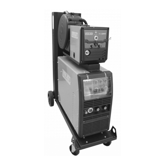
PowerMTS 400
FUNCTION: MIG/DC Stick/DC TIG Welder
PURCHASE DATE:
MODEL NAME:
SERIAL NUMBER:
OPTIONAL ACCESSORY SERIAL NUMBER:
Advertisement
Table of Contents

Related Manuals for Everlast PowerMTS 400


Summary of Contents for Everlast PowerMTS 400
- Page 1 Publish Date: 8-25-2023 EVPMTS400 Rev. 1 USA/North America ©Everlast Power Equipment 400/315A Safety, Setup and General Use Guide For The PowerMTS 400 400/300A 400/300A FUNCTION: MIG/DC Stick/DC TIG Welder PURCHASE DATE: MODEL NAME: SERIAL NUMBER: OPTIONAL ACCESSORY SERIAL NUMBER: Operator’s Manual...
-
Page 2: Table Of Contents
TABLE OF CONTENTS SPECIAL NOTICE AND CALIFORNIA PROPOSITION 65 WARNING CUSTOMER GREETING AND EXPLANATION OF PROCEDURES WARRANTY AND CONTACT INFORMATION SAFETY DISCLAIMER AND HF WARNING SAFETY WARNINGS, DANGERS, CAUTIONS AND INSTRUCTIONS GENERATOR OPERATION INFORMATION / 240V 1 PHASE AND 480V 3 PHASE OPERATION SPECIFICATIONS DUTY CYCLE INFORMATION AND EXPLANATION BREAKER AND WIRING REQUIREMENT INFORMATION... -
Page 3: Special Notice And California Proposition 65 Warning
Due to multiple variables that exist in the welding field and the changing nature of it and of the Everlast product line, Everlast Power Equipment INC. does not guarantee the accuracy, completeness,... -
Page 4: Customer Greeting And Explanation Of Procedures
Many issues can be resolved over the phone. If the issue cannot be resolved over the phone/email, you may be given an op- tion to return the unit, or have a part shipped to you, at Everlast’s discretion. Keep in mind, you may be asked questions that seem basic, or ele- mentary to your knowledge base. -
Page 5: Warranty And Contact Information
Warranties and service policies and procedures vary from country to country and are maintained and supported by the region- al or in country distributor of Everlast welding equipment. USA Customers Only: For full details on the 5 year parts and labor warranty, 30 day satisfaction policy, terms of sale, and how to proceed with a war- ranty claim, please visit: https://www.everlastgenerators.com/standard-warranty. -
Page 6: Safety Disclaimer And Hf Warning
Safe operation and proper maintenance is your responsibility. Everlast is dedicated to keeping safety a top priority. While we have compiled this operator’s manual to instruct you in basic safe operation and maintenance of your Everlast product, it is no substitute for observing safe welding practices and behavior. Safe welding and related cutting operations require basic knowledge, experience and ultimately the exercise of common sense. -
Page 7: Safety Warnings, Dangers, Cautions And Instructions
It is your responsibility to make certain that the use of this welder is restricted to per- sons who have read, understand and follow the warnings and instructions in this manual. If you or the operator needs further instruction, contact Everlast welding support at 1-877 755 -9353 ext. 204 or seek qualified professional advice and training. - Page 8 Safety Warnings, Dangers, Cautions and Instructions DANGER! Welding and cutting operations pose serious inhalation hazards. Some of these hazards are immediate while others are cumulative in their effect. Do not weld in enclosed spaces or in areas without adequate ventilation. Fumes and gases released in the welding and cutting operations can be toxic.
- Page 9 Safety Warnings, Dangers, Cautions and Instructions CAUTION! Trip Hazards exist around this unit. Cords, cables, welding leads and hoses pose a trip hazard. Be aware of their location and inform others of their location. Tape and secure them so they will stay out of high traffic areas. CAUTION! Welded metal can stay hot long after welding is completed.
-
Page 10: Generator Operation Information / 240V 1 Phase And 480V 3 Phase Operation
“shore” type systems. The generator manufacturer determines the THD rating, not Everlast. Do not assume that a name brand generator, or a “new” generator automatically provides clean power. Price paid does not guarantee a clean power output either. -
Page 11: Specifications
Specifications DUTY CYCLE Duty Cycle is simply the amount of time out of a 10 minute period in which the unit can operate. For example, if this unit has a duty cycle of 60% at maximum output (400 A while operating on 480V 3 phase and 315A while operating on 250V 1phase) means that the unit can be operated for 6 minutes out of 10 minutes at the maximum setting. -
Page 12: Breaker And Wiring Requirement Information
Use the I1MAX and the I1EFF ratings listed above to determine the proper breaker and con- ductor (wire) sizing required. Everlast welders are designed around use in industrial wiring applications and are intended to be used with modern elec- trical systems. -
Page 13: General Operating And Electrical Specifications
Specifications Duty Cycle PowerMTS Product Specifications Duty Cycle is simply the amount of time out Construction Type Inverter (IGBT based, Digital Control) of a 10 minute period in which the unit can Input Voltage 240 V 1 Phase, 480V 3 Phase 50/60 Hz (Switched at rear.) operate. -
Page 14: Getting Started, Unpacking Your Unit And Inspection
Other drive roll sizes and types should be purchased 26V Gas Valve Torch (12.5 ft with cable). direct from Everlast. The included drive roll is a V groove drive roll, designed for solid steel wire. Depending upon the region/country... -
Page 15: Connecting Your Unit To The Power Source And Wiring Information
See page 5 for more contact information. NOTICE: Cosmetic damage claims after 30 days will not be accepted, unless Everlast is contacted and informed of such delay and reason for such a required delay (i.e. -
Page 16: Shielding Gas,Regulators, And Torch Installation And Polarity Information
Setup Guide Getting Started 580 CGA valve). If you do not have a cylinder wrench, an adjustable CONNECT YOUR UNIT TO THE CORRECT SHIELDING GAS type wrench will work, but make sure it is properly adjusted to pre- What Shielding Gas Should Be Used? vent rounding of the fitting shoulders. -
Page 17: Assembling And Connecting The Wire Feeder To The Umbilical
Setup Guide Getting Started pressure to tighten the control cable to the wire feeder and the welding CONNECT THE UMBILICAL TO THE WIRE FEEDER . power source. NOTICE: The power connection can be placed in either the The wire feeder controls all wire feed operations and is connected to the positive (+) or the negative (-) DINSE type terminal on the front of the unit via the umbilical cable which is provided which provides separate machine. - Page 18 Do not attempt to use the standard gun unless operating briefly. Performance with the stock gun will be limited Everlast does not offer a flux-cored gun. This must be pur- chased aftermarket. The use of aftermarket guns does not affect warranty.
- Page 19 NOTE: Carbon arc gouging torch, and run with electrode negative polarity, necessary connections are supplied by but this is typical configuration of customer. It is not sold by Everlast. most all rods. Some specialty rods TO AIR COMPRESSOR may only be run electrode negative.
-
Page 20: Installing Mig Wire And Drive Roll Selection, Mig Gun Disassembly And Setup
Setup Guide Getting Started CHECK AND CHANGE YOUR DRIVE ROLL. INSTALLING THE WIRE SPOOLS. The unit comes with a pair of .045” and .062” drive rolls installed. Re- The wire feeder is designed to accept up to 12” diameter rolls, normally member, if you change wire size or type, you will need to either flip both up to 44 lbs. - Page 21 Setup Guide Getting Started the end of the wire is straight and able to be threaded through the wire INSTALL THE WIRE AND FEED THE GUN. feeder mechanism and gun. Once the wire spool has been installed, flip the tensioner lever down and raise the top drive rolls to the upper position.
-
Page 22: Dc Tig Tungsten Selection
Component Identification and Explanation Getting Started SELECT THE PROPER TUNGSTEN TYPE. Purchasing Tungsten can be difficult. Local suppliers tend to put a premium price on Tungsten, and may be three times an online price TUNGSTEN SELECTION direct from a distributor. In many areas, the choice of tungsten may Selecting the correct tungsten for your TIG welder is important. - Page 23 Component Identification and Explanation Getting Started Choosing the proper grind angle is important to achieving the weld As you use the tungsten (depending upon the type you have select- penetration, bead appearance, and arc cone width that you desire. ed) you will notice that the tungsten will gently form more of a point- While there is no true “one size fits all”...
-
Page 24: Need To Know Characteristics Of The Welder
Component Identification and Explanation Getting Started feeder and the display on the power source changes to reflect changes NEED-TO-KNOWS ABOUT THIS WELDER made to the settings. Other aspects of the weld cycle and trigger operation Before delving too deep into the setup and parts identification of the weld- are made on the power source itself. -
Page 25: Mig Gun Care, Selection And Liner Information
The .030” wire diameter should not be used in a gun over 12.5 feet (4m). Purchase of an optional liner and possibly a smaller series gun such as the 15 or 24 series, which are available from Everlast, is recommend- ed for use with these smaller sizes for best performance. -
Page 26: Front Panel View Of The Power Source
Component Identification and Explanation Front Panel View of the Power Source Number Component Identification Component Note Protective Cover Keep cover down and in place during welding activities and in storage. Quick Connect Gas Fitting for MIG Connect to MIG Wire Feeder Control Connector This connects to the wire feeder assembly via the umbilical (not shown, but provided with wire feeder). -
Page 27: Rear Panel View Of The Power Source
First try relocating the welder and affected objects. If no success is obtained, inspect building ground. If noth- ing is found then All metal objects should be attached to a separate ground outside the shop. Contact Everlast for further details. -
Page 28: Fcs 203 Wire Feeder View
Component Identification and Explanation FCS 203 Wire Feeder View # Component Identification Component Note Lift Handle This secure lifting handle is for lifting only. It should not be used to suspend the wire feeder. To suspend the wire feeder, tap into the bottom skid and use it to suspend the wire feeder. -
Page 29: Control Panel Layout Information And Operation Details
If fan is operating, remove cover and clean unit. If problem persists, discontinue use and contact Everlast Technical Support. If this LED light illuminates, check power input quality. Make sure input power has been selected properly with Over/Under Current Warning the switch on the rear of the unit. - Page 30 Component Identification and Explanation Control Panel Layout Component I.D. Component Note This controls the current output (amps) of the power source while welding in Stick or TIG mode, and while arc gouging. This control is inactive while wire feed welding. Actual welding current (amps) will be reflected in the Welding Current current display.
-
Page 31: Explanation Of Mig And Tig Operation
Select a smaller .023”: 3.5 x Amps = Inches per minute (IPM) torch (from the selection of Everlast MIG torches), a smaller liner, or both .025”: 3.1 x Amps = Inches per minute (IPM) for short circuit use with smaller wires. - Page 32 Component Identification and Explanation Explanation of MIG and TIG Operation more than 5 degrees lean in either side to side direction. age heat build up. For example: when welding vertically weaves are al- most always used to prevent the molten metal from sagging due to the Holding the wire too far off from the metal will result in rough starting and force of gravity.
- Page 33 Component Identification and Explanation Explanation of MIG and TIG Operation with .035” wire and under, create a bead no thicker than 3/16” in a single down side to scratch arc start is that it wears Tungsten much more quickly, pass, no more than 1/8” with .030” wire, and with .025”wire and smaller particularly when the Tungsten becomes hot and a restart is required.
- Page 34 Component Identification and Explanation Explanation of MIG and TIG Operation Joint Preparation DIFFERENT COMMON TYPES OF WELD JOINTS Besides a butt joint (Flat edge to flat edge) and lap joint (overlapping V-GROOVE (60-80°) DOUBLE V-GROOVE edges) which are often used for thinner metal gauges, consider using one of these groove joints for best welding results.
- Page 35 Component Identification and Explanation Explanation of MIG and TIG operation PUSHING VS. DRAGGING TECHNIQUES IN MIG MIG Welding is fairly simple if you keep travel angle and direction in mind when welding. See below. If you are welding flux- core, the gun direction is reversed. Remember: If it has gas, you use a push angle. If it is gas-less you use a drag angle. The old welder’s saying “If it has slag, you drag.”...
-
Page 36: Stick Welding Information
Component Identification and Explanation Stick Welding Information STICK ARC STARTING METHODS Make sure the unit is turned on and the boot cycle has finished. Select the Stick Process on the Selector. Make sure the electrode holder is in the Positive connector and the work clamp is in the negative connector. Select the Amp level desired. -
Page 37: Mig Torch Component Breakdown
Component Identification and Explanation North 36 Selekt Series MIG Torch Parts Breakdown... - Page 38 Component Identification and Explanation North 36 Series MIG Consumables and Wear Parts (MB36KD Style) GAS NOZZLES GUN LINERS Part# Material In/Out Length meters Part# Shape Material Nozzle Dia. Length mm Blue Liner .030-.035” Red Liner .035-.045” CONTACT TIPS Part# Material Nozzle Dia. Length mm Yellow Liner .045-.062”...
-
Page 39: Common Welding Issues
Check gas flow. Adjust for higher flow of gas. Listen for audible click of Weld is dirty/oxidized, or porous. is sticking. gas solenoid. If no click is heard, then contact Everlast Support. Clean weld properly. Increase pre flow or post flow. For Flux Core, a certain amount of spatter and smoke is common.
Need help?
Do you have a question about the PowerMTS 400 and is the answer not in the manual?
Questions and answers