Advertisement
Quick Links
CC
CV
GMAW
SMAW
IGBT
1
PHASE
DV
120/240V
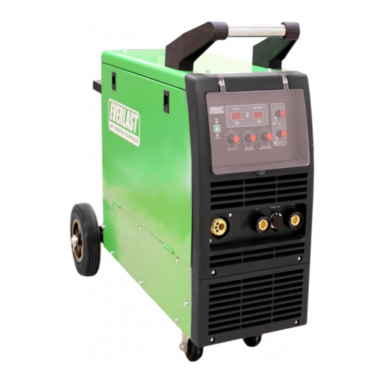
Operator's Manual for the Power i-MIG 315
Safety, Setup and General Use Guide
everlastwelders.com
1-877-755-9353
329 Littlefield Ave. South San Francisco, CA 94080 USA
Rev. 1
Specifications and Accessories subject to change without notice.
0 10531-20
Advertisement

Related Manuals for Everlast Power i-MIG 315


Summary of Contents for Everlast Power i-MIG 315
- Page 1 GMAW SMAW IGBT PHASE 120/240V Operator’s Manual for the Power i-MIG 315 Safety, Setup and General Use Guide Rev. 1 0 10531-20 everlastwelders.com Specifications and Accessories subject to change without notice. 1-877-755-9353 329 Littlefield Ave. South San Francisco, CA 94080 USA...
- Page 2 TABLE OF CONTENTS CUSTOMER GREETING EVERLAST CONTACT INFORMATION SAFETY INSTRUCTIONS PERFORMANCE/DESIGN SPECIFICATIONS ELECTRICAL INPUT/OUTPUT/DUTY CYCLE GENERAL PRODUCT AND USE INFORMATION DUTY CYCLE AND WARNINGS SUMMARY OF FEATURES GENERAL MIG/FLUX-CORED/DRIVE ROLL INFORMATION MIG GUN AND WIRE SPOOL INSTALLATION CONNECTING GAS AND REGULATOR INFORMATION...
- Page 3 Dear Customer, THANKS! You had a choice, and you bought an Everlast product. We appreciate you as a valued customer and hope that you will enjoy years of use from your welder. Please go directly to the Everlast website to register your unit and receive your warranty information. Your unit registration is im- portant should any information such as product updates or recalls be issued.
- Page 4 The owner of this product assumes all liability for its use and maintenance. Everlast Power Equipment INC. does not warrant this product or this document for fitness for any particular purpose, for performance/accuracy or for suitabil- ity of application.
- Page 5 While accidents are never planned, preventing an accident requires careful planning. Stay alert! Please carefully read this manual before you operate your Everlast unit. This manual, if read in full, can as- sist the user in obtaining helpful information concerning the safe operation of this unit. Do not operate the unit until you have read this manual and you are thoroughly familiar with the safe operation of the unit.
- Page 6 Safety Precautions These safety precautions are for protection of safety and health. Failure to follow these guidelines may result in serious injury or death. Be careful to read and follow all cautions and warnings. Protect yourself and others. Welding and cutting processes produce high levels of ultraviolet (UV) radiation that can cause severe skin burn and damage.
- Page 7 Safety Precautions WARNING! Persons with pacemakers should not weld, cut or be in the welding area until they consult with their physician. Some pacemakers are sensitive to EMF radiation and could severely malfunction while welding or while being in the vicinity of someone welding. Serious injury or death may occur! Welding and plasma cutting processes generate electro-magnetic fields and radiation.
- Page 8 Safety Precautions WARNING! Electrical shock can kill. Make sure all electrical equipment is properly grounded. Do not use frayed, cut or otherwise damaged cables and leads. Do not stand, lean or rest on ground clamp. Do not stand in water or damp areas while welding or cutting.
- Page 9 Section 1 Introduction and Specifications General Performance Specifications Power i-MIG 315 MIG/Stick Amp Range MIG 30-315A / DC Stick: 10-200A MIG Output Type Standard, non-pulse, with Flux-Cored Capability. Spool gun ready. (Spool gun is optional) Volt Adjustment Range MIG 15.5-30V (±3V) MIG Wire Feed Speed 60 to 600 IPM (.5-15 m/min) (No load max 700 IPM)
- Page 10 Section 1 Introduction and Specifications Electrical and Performance Specifications EVERLAST Power i-MIG 315 MODEL: Power i-MIG 315 Serial No. EN/ IEC60974.1 240V; DC: 30-315A; 15.5-29.8V 100% 315A 250A 200A 29.8V 26.5V DC: 10-200A; 20.4– 28V 100% 200A 160A 26.4V 240V I...
- Page 11 Be on the lookout for fires, and smoldering materials while and after welding! GENERAL PRODUCT INFORMATION: The inverter-based Power i-MIG 315 is a MIG/Stick unit with production welding capability designed for commercial/ industrial use and applications. (Residential or home shop use is ok as long as wiring codes are followed per Article 630 of the NEC) The unit is intentionally basic, for those users who require simplified setup and for use by multiple operators or with operator’s with limited experience with MIG or stick welding.
- Page 12 If the error does not clear after cycling the switch, immediately cease operation and call Everlast Technical Support. When the “Overcurrent Warn- ing” LED lights and will not clear, the overcurrent has likely caused an internal fault. This is usually a result of a poor power supply, a long extension cable, or from running off of a generator that is malfunctioning or not rated for clean power use.
- Page 13 Section 1 Introduction and Specifications Discussion of Welder Features and Operation SUMMARY OF FEATURES GMAW Process (MIG) and F-CAW (Flux-Cored) The digitally controlled components of this welder precisely control wire feeding and arc quality. It also gives real-time feed back about the weld- ing output parameters.
- Page 14 “bird’s nesting” .035” and .045” wires can be fed in longer length guns. For small wire diameter sizes, Everlast recommends purchasing either the 15 or 24 series gun to handle the smaller wire and to give greater flexibility when welding more delicate items. See the information below for more information regarding gun and drive roll selection.
- Page 15 Section 2 Setup Guide General Product and Use Information MIG/FLUX-CORED WIRE, DRIVE ROLL AND GUN INFORMATION For smooth wire feeding, free of jamming and slipping, the drive rolls must be sized correctly. You must select the proper type and size of drive roll for the size and type of wire used.
- Page 16 Section 2 Setup Guide General Product and Use Information MIG/FLUX-CORED WIRE, DRIVE ROLL AND GUN INFORMATION The MIG gun has a Euro-style quick connect that is used to connect the gun to the welder. This type of connection is the most common throughout the world and most major MIG gun manufacturers can supply any MIG gun in this type of configuration If you need to change your gun to match other guns in your shop (to keep consumables the same), contact the manufacturer of your preferred gun for a replacement gun with this type of back-end.
- Page 17 Section 2 Setup Guide General Product and Use Information MIG/FLUX-CORED WIRE, DRIVE ROLL AND GUN INFORMATION 1.Install the MIG gun as instructed in “To install the MIG gun (torch)” on the previous page. Loosen the top idler roller tensioner, rotating the black tensioner knob counter-clockwise. 2.Flip the tensioner down, toward you, releasing the carrier arm that holds the top drive rolls.
- Page 18 General Product and Use Information NOTICE: The Power i-MIG 315 includes a self-contained undercarriage, which also includes a built-in carrier for the cylinder. This carrier will hold multiple sizes of gas cylinders. However, do not use small cylinders (20 Cu. Ft. or similar sizes) that do not rise above the cylinder yoke, that secures the cylinder with a chain.
- Page 19 Section 2 Setup Guide General Product and Use Information Gas and Electrical Connections FLOATING BALL ADJUSTMENT VALVE 580 CGA CYLINDER PRESSSURE FUSE 1x220V 5/8”-18 RH INERT NEMA 6-50P 50A 240V 1 PHASE PLUG NOTICE: The unit is shipped with a regulator rated for Ar/CO or 100% Argon use only.
- Page 20 Section 2 Setup Guide General Product and Use Information GAS SELECTION Gas selection for different processes and different metals can be confusing. These guides help you remember which gases should be used. However, for MIG, they are not absolute. The suggested gases for MIG are based upon stand- ard, short-circuit mode and do not take into account the axial spray mode.
- Page 21 Section 2 Setup Guide CONNECTIONS AND POLARITY STOP! IMPORTANT! Read the information on this page and the following pages carefully. It contains important information on correct polarity that should be used in the welding process. Incorrect polarity is a common cause of many weld-related problems, particularly when changing processes or wire types.
- Page 22 Section 2 Setup Guide CONNECTIONS AND POLARITY MIG (GMAW) 350EX WORK NOTICE: For MIG, the polarity connection for the gun is located under the spool cover. It must be connected to the positive terminal. MIG requires that the gun be positive polarity and the work clamp be negative polarity.
- Page 23 Section 2 Setup Guide CONNECTIONS AND POLARITY Flux-Cored (F-CAW) 350EX WORK NOTICE: For Flux-Cored, the polarity connection for the gun is located under the spool cover. It must be re-located to the negative terminal. Flux-Cored requires that the gun be negative and the work clamp be positive polarity.
- Page 24 Section 2 Setup Guide CONNECTIONS AND POLARITY MIG (GMAW) with Spool Gun 350EX CONTROL WORK NOTICE: The polarity connection for the Spool gun is located under the cover. The gun polarity should be positive. If welding Flux-Cored wire with the spool gun, use the negative terminal, and configure for Flux-Cored use.
- Page 25 Section 2 Setup Guide CONNECTIONS AND POLARITY Stick (SMAW) 350EX WORK TORCH NOTICE: This is the typical setup for stick welding. Most all welding electrodes use electrode positive as the preferred polarity. Some rods are designated for both polarities. Consult the electrode manufacturer’s recommendations for applications of EN or EP. Operation with old or improperly kept welding electrodes will affect performance.
- Page 26 Section 2 Setup Guide NOTICE: The sections on MIG and Flux-Cored adjustment and operation have been combined since setup and adjust- ment is similar. Where there are exceptions, it will be noted. MIG/Flux-Cored...
- Page 27 Section 2 Setup Guide UNDERSTANDING MIG FUNCTIONS TERMS RELATED TO MIG/FLUX-CORED SETUP Amps. (A) Amps are directly related to wire feed speed in MIG and Flux-Cored operation. The type of wire, the diameter of the Wire and the Wire feed speed govern the amount of current that flows as wire is fed. This is comparable to the rate of “flow” of water.
- Page 28 Section 2 Setup Guide NOTICE: This unit operates multiple classes and sizes of electrodes, except E6010. There are basic differences in how a transformer welder and an in- verter welder handle stick welding. Inverters, including this one, typically prefer a tighter arc. In fact, the action of the arc force control changes the way a user might weld.
- Page 29 Section 2 Setup Guide UNDERSTANDING DC STICK FUNCTIONS TERMS RELATED TO DC STICK FUNCTIONS Amps. This is the measure of the “ flow” of the welder current. Arc Force Control. In stick mode, as arc length drops, so does voltage due to the manual process design. A weld isn’t made with only Amperage, Voltage is also involved.
- Page 30 Section 2 Setup Guide FRONT PANEL POWER I-MIG 315 350EXT...
- Page 31 Section 2 Setup Guide FRONT PANEL POWER I-MIG 315 FRONT PANEL FEATURES Control Connector. This connector serves for use with the spool gun only. The Gun trigger signals the welder to start feed- ing the wire, and to initiate the arc. This connector should be disconnected in standard MIG and Stick mode for safe opera- tion.
- Page 32 Section 2 Setup Guide FRONT UPPER PANEL POWER I-MIG 315...
- Page 33 If none are found con- tact Everlast immediately. If the overcurrent comes on, but resets after cycling the unit off and back on without further issue but does so every so often, this may be caused by too long of an arc starting length, or improperly trimmed wire.
- Page 34 Section 2 Setup Guide FRONT UPPER PANEL POWER I-MIG 315 6. Spot and Stitch Timer. The Spot timer allows the user to set a automatic “off” to the arc cycle after the torch switch is pressed and held. This allows the user to make consistently sized spot or plug welds.
- Page 35 Section 2 Setup Guide SIDE ACCESS PANEL POWER I-MIG 315 1.5s BURN BACK...
- Page 36 3. Four Roll Drive Feeder. The wire feeder features 4 driven rolls. Only the bottom feature removeable rolls. Drive rolls must be matched to the size and type of wire being fed. Order additional drive rolls from Everlast if needed.
- Page 37 Section 2 Setup Guide REAR PANEL POWER I-MIG 315 FUSE 1x220V...
- Page 38 Turn off the unit at the main circuit breaker, and contact Everlast technical. Do not continue to use. Power Input Cable and NEMA 6-50P Plug. The Power i-MIG 315 requires 240 V single phase 50/60 Hz power input. If nec- essary this unit will operate on 208V input as it is within the 10% voltage allowance.
- Page 39 Section 2 Setup Guide 36 SERIES MIG TORCH Expanded View NOTICE: Over time, pressure on the drive rolls causes metal fragments from the filler wire’s surface to find its way to the gun cable liner. If the wire guide is not cleaned, it can gradually clog up and causes wire feed malfunctions.
- Page 40 While Everlast uses the term “arc force” on some models as Even though you will find general recommendations about well as inductance on others. The term is the same function setting the Amps, Volts and even shielding gas through a in MIG.
- Page 41 Section 3 Setup Guide MIG OPERATION AND THEORY machine’s design. However, few MIGs have an adjustable molten puddle begins to cool. This will require the operator inductance. Inductance is part of the personality of a MIG to break it loose and spend time trimming the wire. Even if welder.
- Page 42 Section 3 Basic Theory and Function MIG OPERATION AND THEORY both are correct if used correctly and with each having par- cursive “e” motion are best to begin with. Other weave ticular strength and weakness. Either one done with too patterns can be used of course.
- Page 43 Section 3 Basic Theory and Function MIG OPERATION AND THEORY be prepared with a grinder to accept multiple weld passes. The weldment edges should be ground to form a V, U or J shaped groove to create a recess where the welds can be welded one on top of another.
- Page 44 Section 3 Basic Theory and Function MIG OPERATION AND THEORY Besides a butt joint and lap joint which are often used for V-GROOVE (60-80°) DOUBLE V-GROOVE thinner metal gauges, consider using one of these groove joints for best welding results. When grinding or cutting the bevels, especially with a single V-groove, it may be beneficial to leave a small land with a gap between the joint to achieve U-GROOVE...
- Page 45 Section 3 Basic Theory and Function MIG OPERATION AND THEORY Problem: Gun is not being held vertical from side to side. Wire is not being directed to the center of the puddle. This concentrates heat on one side of the joint and results in poor fusion on the neglect- ed side.
- Page 46 Section 3 Basic Theory and Function MIG OPERATION AND THEORY Characteristics: Concave weld, poor filling, possible undercutting resulting in weak weld. Possible Causes: Voltage too high, not enough wire speed, too short of wire stick out, wrong gun angle. Remedy: Decrease voltage, use push motion, in- crease wire speed.
- Page 47 Section 3 Basic Theory and Function MIG OPERATION AND THEORY Special Notes Concerning Operation. es tend to hold their rust resistance better. But 1. Shielding Gas Selection for MIG and TIG. While to reduce the heat that is put into the weld , and welding aluminum with the Spool gun or MIG reduce warping, there are stainless tri–...
- Page 48 You must purchase a MTS version of the spool gun to operate correctly. You may purchase a compatible spool gun direct- ly from Everlast for your unit. For the best match- up, we recommend the Parker DSP-360. 4. Flux-Core Operation. Flux-Core welding requires the use of serrated drive rollers.
- Page 49 Section 3 Basic Theory and Function STICK OPERATION AND THEORY STICK ARC STARTING METHODS Make sure the unit is turned on and the boot cycle has finished. Select the Stick Process on the Selector. Make sure the electrode holder is in the Positive connector and the work clamp is in the negative connector. Select the Amp level desired.
- Page 50 Wire continues feeding but no arc is wires. Check power plug for problems. If easily tripped the present. Resistor value too low. (Contact Everlast if OC is tripping regularly with normal settings.) Potentiometer damaged. Repair or Replace it.
Need help?
Do you have a question about the Power i-MIG 315 and is the answer not in the manual?
Questions and answers