Advertisement
Quick Links
Publish Date: 3-15-2024
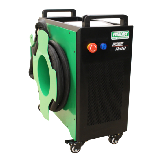
LRS1500-AC
Compact, Air Cooled Fiber Laser
Weld/Cut/Clean/De-rust
1500 Watt Output
1070 nm wavelength
Safety, Setup and General Use Guide for Hand Held
Operation*
FDA Accession#: 2410134-000;
FDA Product Code: 95R—FF
*This is an early release safety and general use guide. It is considered to be a functional manual based off of engineering/factory supplied
data that covers necessary and essential operation information. It also provides basic information for safe operation of the welder. A
more detailed supplemental e- manual will be released in the future with more detailed setup and operation instructions along with more
general data. This supplemental e-manual will be able to be downloaded as soon as it comes available.
Contact:
Everlast Welders:
sales@everlastwelders.com
380 Swift Ave. Unit 12
South San Francisco California, 94080
1-877-755-9353
Sales: Ext 201, Technical Support: Ext 207, Parts Ext. 206
Serial Number:_____________________________
Manufacturing Date:_______________
Purchase Date:________________
LSO Officer:_____________________________________ Employee Initials and Review Date:______________
1
Advertisement

Related Manuals for Everlast REDSABRE 1500


Summary of Contents for Everlast REDSABRE 1500
- Page 1 This supplemental e-manual will be able to be downloaded as soon as it comes available. Contact: Everlast Welders: sales@everlastwelders.com 380 Swift Ave. Unit 12...
- Page 2 NOTICE: This Laser Welder is classified as a CLASS 4 Laser. NOTICE: The purchase or use of this product may require a trained Laser Safety Officer (LSO) to be present on premises and/or installation of a Class 1 laser safety enclosure. Annual reports and/or registration with local and state authorities may also be required.
-
Page 3: California Proposition 65 Warning
WARNING! California Proposition 65 Warning: This product, when used for welding or cutting, produces fumes or gases which contain chemicals known to the State of California to cause birth defects and in some cases, cancer. (California Health & Safety Code § 25249.5 et seq.) Warning: Cancer and/or Reproductive Harm www.P65warnings.ca.gov... -
Page 4: Warranty Notice
WARRANTY NOTICE: Fiber lasers are reliable and can be of service for relatively long periods of time if proper care is taken. The warranty will cover against breakage and repair of the main components in general. However, It does not cover or protect against damage, breakage or wear of consumable items or damaged caused by misuse, neglect or failure to follow operation instructions and warnings. - Page 5 Product Overview: The REDSABRE 1500 is a fiber-type hand held laser system that is designed for welding and cutting related activities. The welder can also be used to clean welds in preparation for the next pass or for preparation for the passivation process.
- Page 6 Secure the unit by unplugging the unit, removing the key and tagging out the unit as properly as regulations require. Seek immediate technical help and professional repair from Everlast. Repairs should not be made by unqualified people. Never allow any untrained person to use or demonstrate the welder.
- Page 7 Model REDSABRE 1500 Air Cooled Fiber Laser Specifications Welding Beam Laser Class Class 4 Pilot Laser Class Class 1 Gun/Torch Head Model SUP21T Input Power 1~240V± 10%,50/60Hz Laser Wave Length 1070nm ± 5 (Ultraviolet, Invisible) Laser Output Power 1500W Maximum...
- Page 8 • If the temperature or environmental conditions change quickly, the YAG crystal, fiber end face and the optical lens will be exposed to moisture and damaged. Stains and cloudiness may form on them causing issues with operation. Be sure to keep the operation environment as stable as possible.
-
Page 9: Laser Safety Notice
welding, cutting or cleaning/derusting/descaling functions is prohibited. • Do not watch the laser beam (visible and invisible beams, because both are present and occupying the same approximate area) without safety eyewear. Do not contact the laser beam or a laser generating component or this welder. Failure to comply will result in retinal damage, blindness or burns. -
Page 10: Electrical Safety
Electrical Safety: • Do not damage power lines and fiber cable. Regularly inspect for damage to the fiber cable. Inspect for signs of cuts, crushing or kinking of the cables. Replace any damaged fiber cable immediately. Replace cut or damaged power cords and plugs. •... - Page 11 • Keep the original packing box for return if needed. • Check the packing list for missing accessories. If anything is missing contact Everlast parts support immediately. • Inspect the components for damage, including the chassis case and torch and fiber components.
- Page 12 and the ground wire is connected from the control board to the connection on the chassis. Do not operate without it . Do not remove or cut ground wire. • When connecting and using the laser torch/gun, do not drop the gun or damage any mating surfaces or connections.
-
Page 13: Basic Setup And Operation
Check to ensure the power light has come on and everything is lighting up properly. • Turn on the laser and select the external control mode. (Some versions vary, consult Everlast tech support before the first start if you have a different version than what is listed below); •... - Page 14 The user should contact Everlast for focus mirror and collimating lens removal and replacement instructions.
- Page 15 enabled. Make sure the laser cannot come in direct contact of the table. Remove the safety clamp from any work surface. Use a socket head key wrench to adjust the two screws ahead located on the top of the gun, which are side by side. The gun should be reclined slightly so the Pilot (Target) beam is seen at a short distance as it would be seen while welding.
- Page 16 • Contact Everlast Tech Support for the Red Sabre 1500 for detailed instructions prior to attempting this adjustment or replacement. All parts must be kept grease, lint and dust free and must be covered during the disassembly process to prevent dust from settling during the service process.
- Page 17 • If the collimating lens needs to be replaced, contact Everlast technical support for a detailed procedure regarding replacement of the lens.
- Page 18 It can also get dirt and smoke in it. This lens can be carefully cleaned with 99% ethanol alcohol and optic/laser lens paper. The lens is serviced by Everlast as a whole assembly, even though the lens itself may be replaced independently of the tray.
- Page 19 The complete replacement of the focus lens is recommended, which include the lens holder. The focus lens may be replaced individually, but it is not serviced or sold currently by Everlast. This is because it is usually best to replace all the parts since the sealing ring can be leaking or can get overheated.
- Page 20 • Make sure the red Pilot/Target laser is adjusted properly before starting this process. • To adjust the welding laser focus, use a thin piece of scap piece of metal (18-14 gauge) at least 4”x4”. Place the metal in the flat position so that it is spaced off the work table by at least one inch.
-
Page 21: Control Panel And Operation
The key switch can be used for temporary stoppage and breaks. The E-Stop may not be used except in the event of an emergency. If the E-Stop fails, contact Everlast Technical support immediately and seek replacement options. Do not attempt to bypass the E-Stop. - Page 22 Touch Screen Operation and Home/Main Screen The touch screen has several pages to it, depending upon the process selected. The sliders indicate on and off or status conditions. In general, the left side of the screen data indicates the settings and values at which the machine is operating.
- Page 23 Laser Welding Technology (Program) Process Screen The technology/process screen allows the user to set up and save welding process parameters. This screen also allows you to save parameters in multiple programs. NOTICE: Touching any setting value on any screen with adjustable settings will bring up the number pad to enter the settings. •...
- Page 24 essentially become a single point light source and will not weld very well. The most commonly used scan speed: 300mm/S, width 2.5mm. • The peak power must be less than or equal to the laser power on the parameter page o Example: If the laser power is set to 1000W, then the value peak power should be set to less than 1000W.
- Page 25 Suggested Welding Settings The welding settings in the chart below are approximate settings. This is not an exhaustive list, but are settings that are fairly common. They may not be correct or appropriate for every application. They are offered only as a starting point. In general, the small wire diameters will be fed faster than larger wire diameters as the thickness of plate goes up.
- Page 26 Main Control Settings The unit allows full adjustment of all operational functions beyond the actual weld settings. To access the weld settings, touch the settings icon on the Home screen and the unit will bring up an access code/pass word screen before it allows changes to be made in the settings. This is designed so the welder base operation parameters cannot be changed arbitrarily except by an authorized administrator or supervisor.
- Page 27 Starting Power Range: 1%-100%. Default: 30% Up Slope Time (Laser On Progressive Time) Range: 0-2000ms. Default 500ms. • The laser programming has the ability to end the weld at a different power setting than the welding output setting. The wattage is gradually decreased, or “sloped” down to the final power setting (Laser off).
- Page 28 Start with a 1.25 setting, then adjust from that point. NOTICE: Scan correction is accomplished through trial and error by experimenting with the visual scan width of the Pilot laser and the actual welded area. • The Laser Center off set parameter calibrates the center of the Pilot Laser. The red Pilot Laser needs to be aligned with the actual target point of the welding beam.
- Page 29 Monitoring Machine Status and Information This unit has a self-monitoring mode available through the home screen which allows the user to access and view machine status. This is helpful in diagnoses and evaluating machine health and functions. Welding, Cutting and Weld Cleaning The Red Sabre is a multi-function welder.
- Page 30 the wire. The push speed should not be impeded by applying counter pressure in any way. If the push is too fast or fusing of the metal is not complete, slow the feeder speed down rather than resist the push of the wire.
- Page 31 Weld Cleaning The Weld Cleaning function is part of the welding function of the machine. It differs from the actual De- scaling and Rust removal programming. The standoff height is different, and a different scan program is used with relatively low wattage. The wattage should only vaporize the oxidation. It should not be set to melt the metal.
- Page 32 Laser Cutting Another function based on the Laser welding programming of the welder is laser cutting. This is designed to make clean and narrow kerf cuts in metals up to 3.5mm. The actual cut capacity is limited however to the metal type and may vary slightly. The cutting function does not use or require argon. The cutting function uses compressed air.
- Page 33 cutting beam is centered in the hole of the cutting tip. Start with a welding tip first to correct and calibrate the aim of the Pilot laser. • Set power to maximum 1500 Watts. If the settings do not allow it,go to the “Settings” program screen and reset maximum wattage value.
- Page 34 Laser De-Rusting/De-Scaling/Paint Removal The Red Sabre may be used to De-Rust and De-Scale metal. It can also to remove paint and coatings from metal. This special process allows rapid removal of rust, mill scale, paint and other coatings from metal items without overheating or deeply etching the metal. The clean width can be up to 60mm wide, depending upon the focal length of the focus lens.
- Page 35 access the program. Use the following steps to access the Laser Cleaning programming designed for De-rusting, De-Scaling and Paint removal: • To access the program while in the Laser Welding Mode, press the recycle symbol located in the top right hand area of the screen •...
- Page 36 Using the Laser Cleaning Program The Laser cleaning home program is not completely different than the operation and function of the laser welding program, but there a few differences with range and control of settings. • In this screen, the laser is enabled and the slider switch should appear to be slid to the right position.
- Page 37 The Laser Cleaning Technology (Program) Screen The Laser Cleaning technology screen assists the user in making the basic adjustments in the cleaning settings. You will notice that the scanning speed has changed to scanning frequency. The other frequency refers to the laser operation itself. There are less programmable features. There are only two available.
- Page 38 The Laser Cleaning Settings Screen. The laser cleaning settings screen allows the full range of settings to be adjusted and gives master control over all the settings, ranges and functions. The use of the cleaning settings function is password protected to prevent unauthorized access. •...
- Page 39 • When the focal length and gun head have been entered, the machine will automatically go back to the settings page with the new parameter limits established in the programming. • The settings and ranges below are important to how efficient the cleaning function performs. The maximum power (wattage) sets the strength of the cleaning action.
- Page 40 The maximum operating temperatures of the gun components is 70°C (158° F). However, it is not recommended to set the maximum tolerance temperature that high. It can reduce service life of the gun and components. Set mirror and collimator temperature to 50°C (122°F) ▪...
- Page 41 • Adjust the cleaning to 300W • Set scan width to maximum setting if it is a large piece. Set to a low setting for small or narrow objects • Holding the gun approximately 2 feet away from the metal, aim the gun toward the part being cleaned.
- Page 42 Wire Feeder Use and Installation The wire feeder for the laser is similar to a MIG welder feeder. A user familiar with MIG welders will find the unit fairly straight forward and easy to setup and load. The main difference is that there is only a conduit instead of a gun attached to it and the feeder does not provide welding power.
- Page 43 • Install the wire tube into the feeder as shown below. Make sure the tube is fully inserted and tightened into the assembly. This part is brass. Be careful about overtightening Match the copper wire tip up to the wire size installed. Attach the tube to the Gun Head bracket •...
- Page 44 Wire Feeder Use and Programming The display has two pages: The home page and the Settings page. These pages are used to setup, calibrate and synchronize the wire feeder with the timing of the laser beam “turn-on”. The feeder should always be powered up while the laser is in use if wire is to be used. Always check control connections before use.
- Page 45 Fine Tuning the Settings The settings menu is accessed from the home screen. These settings help to define and fine tune the behavior of the feeder when the gun trigger is pulled and the laser beam starts. For some circumstances programming a slight delay in the wire feed is helpful so that a puddle can start and the beam does not hit cold wire before the weld puddle has had time to develop.
- Page 46 • Manual wire feed speed programs the wire jog “cold feed” speed. This feeds at a much faster rate than the welding speed feed out. Set the feed rate here in the settings menu. It’s recommended not to exceed three times the feed rate. •...
-
Page 47: Maintenance
Maintenance: item Method Objective Remarks Cleaning housing and Use clean cotton rag to external equipment cleaning wipe surface dust If there are cracks or spots Replace, Make sure that Remove lens and scrub with no coated surface is in the lint free cotton cloth dipped Cleaning protective oil, dust removal... - Page 48 Annual Maintenance Check Contact Everlast. This is an in depth maintenance and service check. Fault analysis and troubleshooting methods fault phenomenon analysis of causes Exclusion methods remarks 1, power supply no power or 1, restore power lack of phase 2, emergency stop switch 2, Rotate emergency 1.
- Page 49 This unit includes a diagnosis cable and USB designed for laptop use. Keep this stored securely. In the event of a failure, call Everlast Tech Support for a walk through of how to properly use the diagnosis feature/function. Do not attempt any repair your self until you have contacted Everlast technical support.
- Page 51 Do not touch electrically live parts or Keep flammable materials away. Wear eye, ear and body protection. • • • WARNING electrode with skin or wet clothing. Insulate yourself from work and • ground. Spanish No toque las partes o los electrodos bajo Mantenga el material combustible Protéjase los ojos, los oídos y el AVISO DE...
- Page 52 Keep your head out of fumes. Turn power off before servicing. Do not operate with panel open or • • • WARNING Use ventilation or exhaust to remove guards off. • fumes from breathing zone. Spanish Los humos fuera de la zona de res- •...
Need help?
Do you have a question about the REDSABRE 1500 and is the answer not in the manual?
Questions and answers