Table of Contents
Advertisement
EVERLAST
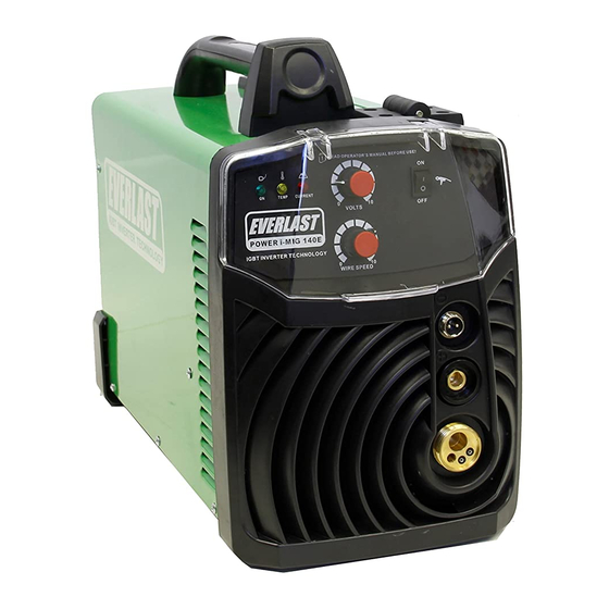
POWER i-MIG 140E
MIG/GMAW WELDER
CV
GMAW
IGBT
DC
Operator's Manual for the
Power i-MIG 140E MIG Welder
General Use and Setup Guide
Rev. 1
0 1000722-14
everlastwelders.com
Specifications and Accessories subject to change without notice.
1-877-755-9353
329 Littlefield Ave. South San Francisco, CA 94080 USA
Advertisement
Table of Contents

Related Manuals for Everlast POWER i-MIG 140E


Summary of Contents for Everlast POWER i-MIG 140E
- Page 1 EVERLAST POWER i-MIG 140E MIG/GMAW WELDER GMAW IGBT Operator’s Manual for the Power i-MIG 140E MIG Welder General Use and Setup Guide Rev. 1 0 1000722-14 everlastwelders.com Specifications and Accessories subject to change without notice. 1-877-755-9353 329 Littlefield Ave. South San Francisco, CA 94080 USA...
-
Page 2: Table Of Contents
Table of contents Section……………………………………………….Page Letter to the Customer …………………..………… Everlast Contact Information…………….…………. Safety Precautions…………………………………… Introduction and Specifications…..………………… General Description, Purpose and Features……… Set Up Guide and Component Identification….…... Suggested Settings…….…………………...……….. Installation of Filler Wire and Machine Setup……... Front Panel View……………………...…………..…. -
Page 3: Letter To The Customer
Your unit registration is important should any information such as product updates or re- calls be issued. It is also important so that we may track your satisfaction with Everlast products and services. If you are unable to register by website, contact Everlast directly through the sales department at the main customer service number in your country. -
Page 4: Everlast Contact Information
Model number: ____________________________ Date of Purchase:___________________________ EVERLAST Contact Information Everlast US: Everlast consumer satisfaction email: sales@everlastwelders.com Everlast Website: everlastwelders.com Everlast Technical Support: support@everlastwelders.com Everlast Support Forum: http://www.everlastgenerators.com/forums/index.php Main toll free number: 1-877-755 WELD (9353) 9am—5pm PST M-F 11am-4pm PST Sat. -
Page 5: Safety Precautions
Safe operation and proper maintenance is your responsibility. We have compiled this operator’s manual, to instruct you in basic safety, oper- ation and maintenance of your Everlast product to give you the best possible experience. Much of welding and cutting is based upon experience and com- mon sense. - Page 6 SAFETY PRECAUTIONS These safety precautions are for protection of safety and health. Failure to follow these guidelines may result in serious injury or death. Be careful to read and follow all cautions and warnings. Protect yourself and others. Welding and cutting processes produce high levels of ultraviolet (UV) radiation that can cause severe skin burn and damage.
- Page 7 SAFETY PRECAUTIONS WARNING! Persons with pacemakers should not weld, cut or be in the welding area until they consult with their physician. Some pacemakers are sensitive to EMF radiation and could severely malfunction while welding or while being in the vicinity of someone welding.
- Page 8 SAFETY PRECAUTIONS WARNING! Electrical shock can kill. Make sure all electrical equipment is properly grounded. Do not use frayed, cut or otherwise damaged cables and leads. Do not stand, lean or rest on ground clamp. Do not stand in water or damp areas while weld- ing or cutting.
-
Page 9: Introduction And Specifications
Section 1 Introduction and Specifications Overview of Parameters and Features Power i-MIG 140E Power i-MIG 140E Specification Construction Type IGBT Inverter Dimensions 17.5”L x 13.5”H x 8.5”W Weight (Unit Only) 25 lbs. Input Voltage/Phase/Hertz 115Volt (110-120V) 1 Phase/ 50/60Hz Maximum Input Amps (I1MAX) 38.6V... -
Page 10: 1.1 General Description, Purpose And Features
1.1 General Description, Purpose and Features. NOTE: For flux core use, special drive rolls with a serrat- The Power i-MIG 140E is a durable MIG (GMAW) welder ed design may be purchased from Everlast. designed for light repair and fabrication where 240V service is limited or not practical. - Page 11 Contact Everlast if of feeding. Make sure to change contact tip size the overcurrent cannot be cleared or reoccurs repeat- when changing the wire size.
- Page 12 Section 1 Introduction and Specifications regulator and slowly open the regulator with the prevent this, regularly remove the wire from the front and top of the regulator facing away from cable, and blow dry compressed air down the gun you. Gas flow requirements vary in MIG greatly neck with the contact tip removed.
- Page 13 NOTE: Some sound. The sound should be regular, and the arc guns Everlast sells may have a separate control should be visually stable without significant pop- mounted on the spool gun handle for wire speed, but ping and snapping.
-
Page 14: Setup Guide And Component Identification
Section 2 Setup Guide and component Identification General Reference Information for Operation and Parameters GENERAL POLARITY RECOMMENDATIONS* Table 1 *Consult manufacturer directions of filler material. There are exceptions. PROCESS TORCH POLARITY WORK POLARITY MIG (GMAW) FLUX CORE (FCAW) GAS SELECTION GUIDE Table 2 PROCESS MIG (GMAW) STEEL... -
Page 15: Installation Of Filler Wire And Machine Setup
Pull the drive roll off, and flip the drive roll over. Reassemble and tighten roller. If a flux core roller is needed contact Everlast. Thread straightened wire into coiled sheath and over grooves in lower drive roll. -
Page 16: Front Panel View
Section 2 Setup Guide and component Identification FRONT VIEW 1. LED Indicators: ON/TEMP/OVERCURRENT 2. VOLTAGE ADJUSTMENT 3. WIRE SPEED/AMP ADJUSTMENT 4. SPOOL GUN SWITCH WIRE SPEED 5. SPOOL GUN CONTROL 6. WORK CLAMP CONNECTOR 3. EURO QUICK CONNECT FOR MIG/SPOOL GUN... - Page 17 Once the cause has been remedied, turn the power off and back on to re- set the welder. If the light does not clear after remedying the cause, contact Everlast technical support for further diagnosis. 2. Voltage Selector. The voltage selector increases and decreases the voltage incrementally through- out the range.
-
Page 18: Side View
Section 2 Setup Guide and component Identification SIDE VIEW 2. Polarity Connection 1. Wire Spool Holder Assy. 4. Wire Feeder Assy. - Page 19 When installing an 8” roll, the wire cleanly while using steel or stainless wire. You may collar will serve as the carrier for the larger diame- purchase additional drive rolls from Everlast for ter roll. When the outer hub is correctly inserted flux core use.
-
Page 20: Rear Panel View
Section 2 Setup Guide and component Identification REAR VIEW/BACK PANEL 2. Main Power Switch 1. Gas Connector (Barb Type) 3. Power Input Cable 4. Fan... - Page 21 Section 2 Setup Guide and component Identification Rear Panel: 1. Gas Supply. Connect the Gas regulator hose to this point via the brass barb fitting. The hose barb connection must be tight to prevent gas leakage. Install an extra clamp if needed to prevent gas from escaping.
-
Page 22: Expanded View Of Mig Torch
Section 2 Setup Guide and component Identification EXPANDED VIEW OF MIG TORCH PARTS Diffuser D.12 14-15AK NOTE: Some components may appear slightly different as design/ Contact Tip 0.8/M6*25 supplier changes are made from time to time. At time of publication, 15AK Goose gun neck assy. -
Page 23: Trouble Shooting
Section 3 Trouble Shooting Trouble Possible Cause Solution Switch damaged Replace Unit is switched on, but the Circuit breaker tripped or power light isn’t on Reset breaker, plug in unit. unit unplugged Check fan shroud housing and wire pro- After welding machine is Fan damaged or jammed tective guard for damage overheating and the fan does... -
Page 24: General Notes
GENERAL NOTES: 1. While welding aluminum with the Spool gun or MIG gun you must use 100% argon. You cannot use a mix as you would with steel or stainless. 2. While welding aluminum with the Spool gun or MIG gun you must use the next size up tip or a special oversize tip for the wire because the heat will cause the aluminum wire to swell and it will either drag or seize in the tip.
Need help?
Do you have a question about the POWER i-MIG 140E and is the answer not in the manual?
Questions and answers