
Related Manuals for Everlast Power MTS 400


Summary of Contents for Everlast Power MTS 400
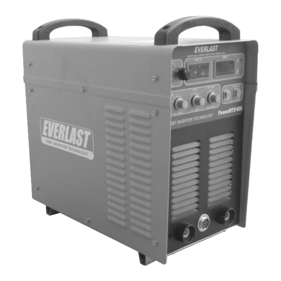
- Page 1 EVERLAST POWER CC/CV MULTI-PROCESS WELDER GMAW/FCAW/GTAW/SMAW/aCAC Operator’s Manual for the Power MTS 400 Safety, Setup and General Use Guide Rev. 1 0 00131-11...
- Page 2 Table of contents Section……………………………………………….Page Letter to the Customer …………………..………… Everlast Contact Information…………….…………. Safety Precautions…………………………………… Introduction and Specifications…..………………… Setup Guide and Component ID…………………… Welder Front View………………...……….………… Welder Rear View…..……………………………….. Wiring Connection…………………………………… Wire Feeder Front View…………….……………….. General Setup and Connection Overview……..….. Recommended Polarity…………...………….……...
- Page 3 Your unit registration is important should any information such as product updates or re- calls be issued. It is also important so that we may track your satisfaction with Everlast products and services. If you are unable to register by website, contact Everlast directly through the sales department through the main customer service number in your country.
- Page 4 Model number: ____________________________ Date of Purchase___________________________ EVERLAST Contact Information Everlast US: Everlast consumer satisfaction email: sales@everlastwelders.com Everlast Website: everlastwelders.com Everlast Technical Support: support@everlastwelders.com Everlast Support Forum: http://www.everlastgenerators.com/forums/index.php Main toll free number: 1-877-755 WELD ( 9353 ) 9am—5pm PST M-F 11am-4pm PST Sat.
-
Page 5: Safety Precautions
Safe operation and proper maintenance is your responsibility. We have compiled this operator’s manual, to instruct you in basic safety, oper- ation and maintenance of your Everlast product to give you the best possible experience. Much of welding and cutting is based upon experience and com- mon sense. - Page 6 SAFETY PRECAUTIONS These safety precautions are for protection of safety and health. Failure to follow these guidelines may result in serious injury or death. Be careful to read and follow all cautions and warnings. Protect yourself and others. Welding and cutting processes produce high levels of ultraviolet (UV) radiation that can cause severe skin burn and damage.
- Page 7 SAFETY PRECAUTIONS WARNING! Persons with pacemakers should not weld, cut or be in the welding area until they consult with their physician. Some pacemakers are sensitive to EMF radiation and could severely malfunction while welding or while being in the vicinity of someone welding.
- Page 8 SAFETY PRECAUTIONS WARNING! Electrical shock can kill. Make sure all electrical equipment is properly grounded. Do not use frayed, cut or otherwise damaged cables and leads. Do not stand, lean or rest on ground clamp. Do not stand in water or damp areas while weld- ing or cutting.
- Page 9 Power MTS 400 Technical Parameters* Section 1 Intro- EVERLAST INVERTER TECHNOLOGY = Open Circuit Voltage = Input Voltage = Output Voltage = Inrush Current ( Maximum Amp Demand) 1max = Operating Current ( Amperage use after start) 1 ef f...
-
Page 10: Introduction And Specifications
Section 1 Introduction and Specifications 1.1 General Description, Purpose and Fea- tures. The PowerMTS, is a CV/CC power source capable of 5 different welding pro- Figure 1.2.1 cesses at a 60% duty cycle at the full rated power while connected to 460V 3 phase. Op- reduces size, weight, and power consumption, eration in 220V 1 phase is limited to 250 while increasing arc stability. - Page 11 Section 1 Introduction and Specifications 3) Do not restrict air flow or movement of MIG or Flux core with the use of down air around the welder. Allow a buffer slope and crater fill functions while in 4T distance of 1-2 ft from all sides if possi- mode improve weld quality.
- Page 12 Section 2 Setup Guide and component Identification MAIN WELDER/POWER SOURCE FRONT VIEW Volt Meter Amp Display EVERLAST Power Indicator Process Selector MIG/F.Core: Crater Fill Voltage Over Current/ Duty Cycle MIG/F.Core: Crater Fill Amps Gas Purge/ Wire Advance TIG/Stick/Carbon Arc: Main Amps...
- Page 13 Section 2 Setup Guide and component Identification 1. Volt Meter. Displays active voltage arc force needed. Each user will even- while welding and displays preset volt- tually find their own balance where the age while the welder is idle. inductance arc force works best for 2.
- Page 14 If the light remains on after sufficient cooling time, contact Everlast Support. 13. Power Indicator. This light should re- main on while the switch is on. 14. Amp Display. The display displays pre-...
- Page 15 Section 2 Setup Guide and component Identification MAIN WELDER/POWER SOURCE REAR VIEW WARNING! Select the proper input volt- age before connecting unit to the power source. The unit will function on 220V 1 phase or 460 3 phase only! Proper wiring is essential. Specifications Current Selection Warning Back Panel...
- Page 16 3. Main Power Switch. Cycling the switch turns the unit either on or off. Switch should snap into position. If fault is found with the switch contact Everlast Support. 4. Main Input Cable. Inspect the cable periodically to ensure that there is no damage from cuts, cracking, or burns.
- Page 17 Setup Guide and component Identification WIRE FEEDER FRONT VIEW LIFT TO ACCESS SPOOL Transport Handle Wire Spool Cover Amp/Wire Speed Voltage Euro Style Torch/Gun Quick Connector EVERLAST M600 WIRE FEEDER Figure C Keep feeder stable and level! Place on flat, level surface. EVERLAST...
- Page 18 Section 2 Setup Guide and component Identification 1. Wire Spool Cover. Protects the wire spool from moisture and dirt. Keep in place and lowered while in operation and storage to protect the wire from deterioration and excess dirt and rust formation.
- Page 19 Section 2 Setup Guide and component Identification CONNECTION OVERVIEW Power Input: 240v1phase OR 460V 3 phase (Plug not included; customer supplied) NOTE: You must select correct voltage /phase on rear of the unit before use or severe damage may occur! Regulator MIG: Ar/CO2 or CO2 TIG: Ar ONLY!
- Page 20 Reinsert and tighten the hand nut clockwise. Tension roll with hand nut so that the roll doesn’t free wheel. Clip end of wire to feed wire smoothly through drive mechanism. Lower Cover EVERLAST CONTROL M600 WIRE FEEDER GAS (BARB) INCHING TO INSTALL MIG GUN/TORCH: Align pins on the torch connector with the feeder receptacle.
- Page 21 General Recommendations Section 3 TABLE 2. SUGGESTED MIG (GMAW) PARAMETERS WELDING AMPS WELDING VOLTS WIRE DIAMETER 60-80 17-18 1.0 mm/.040” 80-130 18-21 1.0-1.2 mm/.040”-.045” 130-200 20-24 1.0-1.2 mm/.040”-.045” 200-250 24-27 1.0-1.2 mm/.040”-.045” 250-350 26-32 1.2-1.6 mm/.045”-.065” 350+ 1.6 mm/.065” TABLE 3. SUGGESTED STICK (SMAW [MMA]) PARAMETERS METAL THICKNESS ELECTRODE SIZE WELDING AMPS...
-
Page 22: Trouble Shooting
Section 4 Trouble Shooting TABLE 6 Trouble Possible Cause Remedy Indicator lamp does not come on when (1) Phase/Wiring incorrect (1) Check power supply machine is switched ON. (2) Main unit switch is damaged (2) Change Breaker Switch (1) Circuit breaker is damaged. (1) Replace (2 ) IGBT module is damaged (2) Replace... - Page 23 APPENDIX A: MAIN COMPONENT LIST Item Specification Circuit Breaker DZ47-60(40A/3P) 3-phase rectifier module MDS100A/1600V (small) Polypropylene capacitor MFD-DA01-1250VDC-40μF±5% IGBT module SKM75GB128D Polypropylene capacitor MFD-DA01 4uF/500VAC±5% Main transformer MTS 400M .3.1.0 Fast recovery diode module DKR200AB60 Transformer for ZKB/QDB ARC400.3.1-1 Transformer for ZKB/QDB MTS400M(ZA).4.1-1 Fuse 2A(6×30mm)
- Page 24 APPENDIX B: MAIN UNIT SCHEMATIC...
- Page 25 APPENDIX C: WIRE FEEDER SCHEMATIC...
- Page 26 NOTES:...
Need help?
Do you have a question about the Power MTS 400 and is the answer not in the manual?
Questions and answers