Table of Contents
Advertisement
Quick Links
Advertisement
Table of Contents

Related Manuals for Supero SUPERSERVER 6027R-TDARF


Summary of Contents for Supero SUPERSERVER 6027R-TDARF
- Page 1 UPER ® UPER ERVER 6027R-TDARF USER’S MANUAL...
- Page 2 The information in this User’s Manual has been carefully reviewed and is believed to be accurate. The vendor assumes no responsibility for any inaccuracies that may be contained in this document, makes no commitment to update or to keep current the information in this manual, or to notify any person or organization of the updates.
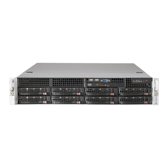
- Page 3 About This Manual This manual is written for professional system integrators and PC technicians. It provides information for the installation and use of the SuperServer 6027R-TDARF. Installation and maintenance should be performed by experienced technicians only. The SuperServer 6027R-TDARF is a high-end server based on the SC825TQ- R740LPB 2U rackmount chassis and the Super X9DRD-iF serverboard.
- Page 4 UPER ERVER 6027R-TDARF User's Manual Chapter 5: Advanced Serverboard Setup Chapter 5 provides detailed information on the X9DRD-iF serverboard, including the locations and functions of connections, headers and jumpers. Refer to this chapter when adding or removing processors or main memory and when reconfi guring the serverboard.
- Page 5 Preface Notes...
-
Page 6: Table Of Contents
UPER ERVER 6027R-TDARF User's Manual Table of Contents Chapter 1 Introduction Overview ......................1-1 Serverboard Features ..................1-2 Processors ...................... 1-2 Memory ......................1-2 SATA ........................ 1-2 I/O Ports ......................1-2 Onboard Graphics ................... 1-2 Server Chassis Features ................1-3 System Power .................... - Page 7 Table of Contents Control Panel LEDs ..................3-2 Power Fail ....................... 3-2 Information LED ....................3-2 NIC1 ........................ 3-2 NIC2 ........................ 3-2 HDD ......................... 3-3 Power ......................3-3 Drive Carrier LEDs ..................3-3 Chapter 4 System Safety Electrical Safety Precautions ................4-1 General Safety Precautions ................
- Page 8 UPER ERVER 6027R-TDARF User's Manual Chapter 6 Advanced Chassis Setup Static-Sensitive Devices .................. 6-1 Precautions ..................... 6-1 Unpacking ....................... 6-1 Control Panel ....................6-2 System Fans ....................6-3 System Fan Failure ..................6-3 Replacing System Fans .................. 6-3 Drive Bay Installation/Removal ............... 6-4 Accessing the Drive Bays ................
-
Page 9: Chapter 1 Introduction
Chapter 1 Introduction Overview The SuperServer 6027R-TDARF is a high-end server comprised of two main subsystems: the SC825TQ-R740LPB 2U chassis and the X9DRD-iF serverboard. Please refer to our web site for information on operating systems that have been certifi ed for use with the system (www.supermicro.com). -
Page 10: Serverboard Features
ERVER 6027R-TDARF User's Manual Serverboard Features At the heart of the SuperServer 6027R-TDARF lies the X9DRD-iF, a dual proces- sor serverboard based on Intel's C600 chipset. Below are the main features of the X9DRD-iF (see Figure 1-1 for a block diagram of the chipset). -
Page 11: Server Chassis Features
Chapter 1: Introduction Server Chassis Features The SC825TQ-R740LPB is designed to be used in a 2U rackmount confi guration. The following is a general outline of the main features of the SC825TQ-R740LPB server chassis. System Power The SC825TQ-R740LPB features a redundant 740W power supply composed of two separate power modules. - Page 12 UPER ERVER 6027R-TDARF User's Manual Figure 1-1. Intel C600 Chipset: System Block Diagram Note: This is a general block diagram. Please see Chapter 5 for details. (C,D) (A,B) (C,D) (A,B) (A,B) (A,B) (C,D) (A,B) (A,B) (C,D) PROCESSOR 2 (right) PROCESSOR 1 (left) W25Q128 PEG0 [0..3] AHCI...
-
Page 13: Contacting Supermicro
Chapter 1: Introduction Contacting Supermicro Headquarters Address: Super Micro Computer, Inc. 980 Rock Ave. San Jose, CA 95131 U.S.A. Tel: +1 (408) 503-8000 Fax: +1 (408) 503-8008 Email: marketing@supermicro.com (General Information) support@supermicro.com (Technical Support) Web Site: www.supermicro.com Europe Address: Super Micro Computer B.V. Het Sterrenbeeld 28, 5215 ML 's-Hertogenbosch, The Netherlands Tel:... - Page 14 UPER ERVER 6027R-TDARF User's Manual Notes...
-
Page 15: Chapter 2 Server Installation
Precautions in the next section. Preparing for Setup The box the SuperServer 6027R-TDARF was shipped in should include two sets of rail assemblies, two rail mounting brackets and the mounting screws you will need to install the system into the rack. Follow the steps in the order given to complete the installation process in a minimum amount of time. -
Page 16: Rack Precautions
UPER ERVER 6027R-TDARF User's Manual • This product is for installation only in a Restricted Access Location (dedicated equipment rooms, service closets and the like). • This product is not suitable for use with visual display work place devices acccording to §2 of the the German Ordinance for Work with Visual Display Units. -
Page 17: Rack Mounting Considerations
Chapter 2: Server Installation Rack Mounting Considerations Ambient Operating Temperature If installed in a closed or multi-unit rack assembly, the ambient operating tempera- ture of the rack environment may be greater than the ambient temperature of the room. Therefore, consideration should be given to installing the equipment in an environment compatible with the manufacturer’s maximum rated ambient tempera- ture (Tmra). -
Page 18: Installing The System Into A Rack
UPER ERVER 6027R-TDARF User's Manual Installing the System into a Rack This section provides information on installing the SC825 chassis into a rack unit with the quick-release rails provided. There are a variety of rack units on the market, which may mean the assembly procedure will differ slightly. You should also refer to the installation instructions that came with the rack unit you are using. - Page 19 Chapter 2: Server Installation Figure 2-1: Separating the Rack Rails Separating the Inner and Outer Rails Rail Assembly 1. Locate the rail assembly in the chassis packaging. Extending the Rails 2. Extend the rail assembly by pulling it outward. 3. Press the quick-release tab. Quick- 4.
-
Page 20: Outer Rack Rails
UPER ERVER 6027R-TDARF User's Manual Figure 2-2. Assembling the Outer Rails Outer Rack Rails Outer rails attach to the rack and hold the chassis in place. The outer rails for the SC825 chassis extend between 30 inches and 33 inches. Installing the Outer Rails to the Rack 1. - Page 21 Chapter 2: Server Installation Figure 2-3. Installing the Rack Rails Installing the Chassis into a Rack 1. Extend the outer rails as illustrated above. 2. Align the inner rails of the chassis with the outer rails on the rack. 3. Slide the inner rails into the outer rails, keeping the pressure even on both sides.
- Page 22 UPER ERVER 6027R-TDARF User's Manual Notes...
-
Page 23: Chapter 3 System Interface
Chapter 3: System Interface Chapter 3 System Interface Overview There are several LEDs on the control panel as well as others on the drive carriers to keep you constantly informed of the overall status of the system and the activ- ity and health of specifi... -
Page 24: Control Panel Leds
SUPERSERVER 6027R-TDARF User's Manual Control Panel LEDs The control panel located on the front of the chassis has several LEDs. These LEDs provide you with critical information related to different parts of the system. This section explains what each LED indicates when illuminated and any corrective action you may need to take. -
Page 25: Hdd
Chapter 3: System Interface On the SuperServer 6027R-TDARF, this LED indicates hard drive and/or DVD-ROM drive activity when fl ashing. Power Indicates power is being supplied to the system's power supply units. This LED should normally be illuminated when the system is operating. - Page 26 SUPERSERVER 6027R-TDARF User's Manual Notes...
-
Page 27: Chapter 4 System Safety
System Safety Electrical Safety Precautions Basic electrical safety precautions should be followed to protect yourself from harm and the SuperServer 6027R-TDARF from damage: • Be aware of the locations of the power on/off switch on the chassis as well as the room's emergency power-off switch, disconnection switch or electrical outlet. -
Page 28: General Safety Precautions
UPER ERVER 6027R-TDARF User's Manual • Serverboard Battery: CAUTION - There is a danger of explosion if the onboard battery is installed upside down, which will reverse its polarites (see Figure 4-1). This battery must be replaced only with the same or an equivalent type recommended by the manufacturer. -
Page 29: Esd Precautions
Chapter 4: System Safety • After accessing the inside of the system, close the system back up and secure it to the rack unit with the retention screws after ensuring that all connections have been made. ESD Precautions Electrostatic discharge (ESD) is generated by two objects with different electrical charges coming into contact with each other. -
Page 30: Operating Precautions
UPER ERVER 6027R-TDARF User's Manual Operating Precautions Care must be taken to assure that the chassis cover is in place when the 6027R- TDARF is operating to assure proper cooling. Out of warranty damage to the system can occur if this practice is not strictly followed. Figure 4-1. -
Page 31: Chapter 5 Advanced Serverboard Setup
Chapter 5: Advanced Serverboard Setup Chapter 5 Advanced Serverboard Setup This chapter covers the steps required to install processors and heatsinks to the X9DRD-iF serverboard, connect the data and power cables and install add-on cards. All serverboard jumpers and connections are described and a layout and quick reference chart are included in this chapter. -
Page 32: Processor And Heatsink Installation
UPER ERVER 6027R-TDARF User's Manual Processor and Heatsink Installation Notes: • Always connect the power cord last and always remove it before adding, re- moving or changing any hardware components. Make sure that you install the processor into the CPU socket before you install the CPU heatsink. •... - Page 33 Chapter 5: Advanced Serverboard Setup 3. With the lever labeled 'Close 1st' fully retracted, gently push down on the 'Open 1st' lever to open the load plate. Lift the load plate to open it completely. Gently push 4. Using your thumb and the index down to pop the load plate fi...
- Page 34 UPER ERVER 6027R-TDARF User's Manual Warning: You can only install the CPU to the socket in one direction. Make sure that the CPU is properly inserted into the socket before closing the load plate. If it doesn't close properly, do not force it as it may damage your CPU.
-
Page 35: Installing A Passive Cpu Heatsink
Chapter 5: Advanced Serverboard Setup Installing a Passive CPU Heatsink 1. Do not apply any thermal grease to the heatsink or the CPU die -- the re- quired amount has already been applied. 2. Place the heatsink on top of the CPU so that the four mounting holes are aligned with those on the serverboard and the heatsink bracket underneath. -
Page 36: Connecting Cables
UPER ERVER 6027R-TDARF User's Manual Connecting Cables Now that the processors are installed, the next step is to connect the cables to the serverboard. These include the data (ribbon) cables for the peripherals and control panel and the power cables. Connecting Data Cables The cables used to transfer data from the peripheral devices have been carefully routed in preconfi... -
Page 37: I/O Ports
Chapter 5: Advanced Serverboard Setup All JF1 wires have been bundled into single keyed ribbon cable to simplify their con- nection. Connect one end of this cable to JF1 and the other end to the Control Panel printed circuit board, located just behind the system status LEDs in the chassis. See the Connector Defi... -
Page 38: Installing Memory
UPER ERVER 6027R-TDARF User's Manual Installing Memory Note: Check the Supermicro web site for recommended memory modules. CAUTION Exercise extreme care when installing or removing DIMM modules to prevent any possible damage. Installing DIMMs 1. Insert the desired number of DIMMs into the memory slots, starting with slots DIMM1A. - Page 39 Chapter 5: Advanced Serverboard Setup Processors and their Corresponding Memory Modules CPU# Corresponding DIMM Modules CPU1 P1-DIMMA1 P1-DIMMB1 P1-DIMMC1 P1-DIMMD1 CPU2 P2-DIMME1 P2-DIMMF1 P2-DIMMG1 P2-DIMMH1 Processor and Memory Module Population Number of CPU and Memory Population Confi guration Table CPUs+DIMMs (For optmnal performance, install DIMMs in pairs) 1 CPU &...
-
Page 40: Adding Pci Cards
UPER ERVER 6027R-TDARF User's Manual Adding PCI Cards PCI Expansion Slots The server can support low-profi le expansion (add-on) cards in each of the fi ve PCI slots provided on the serverboard. PCI Card Installation Begin by releasing the locking tab that corresponds to the slot you wish to populate. Insert the expansion card into the PCI slot card by pushing down with your thumbs evenly on both sides of the card. -
Page 41: Serverboard Details
Chapter 5: Advanced Serverboard Setup Serverboard Details Figure 5-5. SUPER X9DRD-iF Layout USB2/3 USB0/1 COM2 JUIDB COM1 USB6 BMC CTRL FAN7 LAN2 LAN1 FAN8 LAN CTRL IPMI_LAN JPG1 JPB1 CTRL CLK CTRL JI2C1 JI2C2 X9DRD-iF Rev. 1.02 JBAT1 JITP1 JBT1 CPU2 BIOS CPU1... - Page 42 UPER ERVER 6027R-TDARF User's Manual Jumper Description Default Setting JBT1 Clear CMOS See Section 5-9 C1/JI SMB to PCI-E Slots Off (Disabled) JPB1 BMC Enable/Disable Pins 1-2 (Enabled) JPG1 VGA Enable/Disable Pins 1-2 (Enabled) JPL1 LAN1/LAN2 Enable/Disable Pins 1-2 (Enabled) JWD1 Watch Dog Timer Enable/Disable Pins 1-2 (Reset)
-
Page 43: Connector Defi Nitions
Chapter 5: Advanced Serverboard Setup Connector Defi nitions ATX Power 24-pin Connector Pin Defi nitions (JPW1) Pin# Defi nition Pin # Defi nition Power Connectors +3.3V +3.3V A 24-pin main power supply connector -12V +3.3V (JPW1), two 8-pin CPU power con- nectors (JPW2/3) and one 4-pin power PS_ON connectors (JPW5) are located on the... - Page 44 UPER ERVER 6027R-TDARF User's Manual NIC1/NIC2 LED Indicators NIC1/2 LED Pin Defi nitions (JF1) The NIC (Network Interface Controller) Pin# Defi nition LED connection for LAN port 1 is located on pins 11 and 12 of JF1, and the LED NIC 2 LED connection for LAN Port 2 is on pins 9 and 10.
- Page 45 Chapter 5: Advanced Serverboard Setup Power Button The Power Button connection is located on pins 1 and 2 of JF1. Momentarily Power Button contacting both pins will power on/off the Pin Defi nitions (JF1) system. This button can also be confi g- Pin# Defi...
- Page 46 UPER ERVER 6027R-TDARF User's Manual LAN Port Pin Defi nitions Ethernet Ports Pin# Defi nition Two Ethernet ports (LAN1/LAN2) are TD0+ located next to the VGA port on the I/O Vcc19-LAN back panel. An IPMI Dedicated LAN port TD3+ Link 100 LED is also located above the USB0/1 ports.
- Page 47 Chapter 5: Advanced Serverboard Setup Fan Headers The X9DRD-iF has eight fan headers (Fan1 ~ Fan8). These are all 4-pin fan headers, however pins 1-3 are backward Fan Header compatible with traditional 3-pin fans. Pin Defi nitions A fan speed control setting in the BIOS Pin# Defi...
- Page 48 UPER ERVER 6027R-TDARF User's Manual TPM/Port 80 Header Pin Defi nitions Trusted Platform Module Header Pin # Defi nition Pin # Defi nition The JTPM1 header is used to connect a LCLK Trusted Platform Module (TPM), available LFRAME# <(KEY)> separately from a third-party vendor. A LRESET# +5V (X) TPM is a security device that allows en-...
- Page 49 Chapter 5: Advanced Serverboard Setup T-SGPIO 0/1 Headers Serial Link SGPIO Two T-SGPIO (Serial-Link General Pin Defi nitions Purpose Input/Output) headers on the Pin# Defi nition Defi nition serverboard are for use with the I-SATA ports. These headers are used to com- Ground DATA Out municate with the enclosure manage-...
-
Page 50: Jumper Settings
UPER ERVER 6027R-TDARF User's Manual Jumper Settings Explanation of Jumpers To modify the operation of the serverboard, jumpers can be used to choose between Connector optional settings. Jumpers create shorts Pins between two pins to change the function of the connector. Pin 1 is identifi ed with Jumper a square solder pad on the printed circuit board. - Page 51 Chapter 5: Advanced Serverboard Setup PCI Slot SMB Enable PCI Slot SMB Enable/Disable Use Jumpers JI C1/JI C2 to enable PCI Jumper Settings SMB (System Management Bus) support Jumper Setting Defi nition to improve system management for the Closed Enabled PCI slots.
-
Page 52: 5-10 Onboard Indicators
UPER ERVER 6027R-TDARF User's Manual 5-10 Onboard Indicators LAN1/LAN2 LEDs LAN LED Each Ethernet port has two LEDs. The Connection Speed Indicator yellow LED indicates activity when blink- LED State Defi nition ing while the other LED may be green, No connection or 10 Mb/s amber or off to indicate the speed of the Green... -
Page 53: 5-11 Sata Drive Ports
Chapter 5: Advanced Serverboard Setup 5-11 SATA Drive Ports SATA Port Pin Defi nitions (SATA0 ~ SATA5) SATA Ports/SCU Connectors Pin # Defi nition There are four SATA 2.0 (SATA2~SATA5) Ground and two SATA 3.0 (SATA0 -1) por ts located on the X9DRD-iF. In addition, four SCU connectors (SCU0~3) are also Ground provided on the board. -
Page 54: 5-12 Installing Drivers
UPER ERVER 6027R-TDARF User's Manual 5-12 Installing Drivers After all the hardware and operating system have been installed, you need to install certain drivers. The necessary drivers are all included on the Supermicro CD that came packaged with your serverboard. After inserting this CD into your CD-ROM drive, the display shown in Figure 5-6 should appear. -
Page 55: Superdoctor Iii
Chapter 5: Advanced Serverboard Setup SuperDoctor III ® The SuperDoctor III program is a Web base management tool that supports remote management capability. It includes Remote and Local Management tools. The local management is called SD III Client. The SuperDoctor III program included on the CD-ROM that came with your serverboard allows you to monitor the environment and operations of your system. - Page 56 UPER ERVER 6027R-TDARF User's Manual SuperDoctor III Interface Display Screen (Remote Control) Note: The SuperDoctor III program and User's Manual can be downloaded from the Supermicro web site at http://www.supermicro.com/products/accessories/software/ SuperDoctorIII.cfm. For Linux, we recommend using SuperDoctor II. 5-26...
-
Page 57: Chapter 6 Advanced Chassis Setup
Chapter 6: Advanced Chassis Setup Chapter 6 Advanced Chassis Setup This chapter covers the steps required to install components and perform mainte- nance on the SC825TQ-R740LPB chassis. For component installation, follow the steps in the order given to eliminate the most common problems encountered. If some steps are unnecessary, skip ahead to the step that follows. -
Page 58: Control Panel
UPER ERVER 6027R-TDARF User's Manual Figure 6-1. Front and Rear Chassis Views 3.5" Drive Bays (2) DVD-ROM Drive (optional) USB Ports, COM Port (Optional) Control Panel SATA Drives (8) System Reset Main Power Power Supplies Low-profi le PCI Slots Rear I/O Ports (see Section 5-4) Control Panel The control panel (located on the front of the chassis) must be connected to the JF1 connector on the serverboard to provide you with system status indications. -
Page 59: System Fans
Chapter 6: Advanced Chassis Setup System Fans Three 8-cm hot-swap fans provide the cooling for the system. It is very important that the chassis top cover is properly installed and making a good seal in order for the cooling air to circulate properly through the chassis and cool the components. See Figure 6-2. -
Page 60: Drive Bay Installation/Removal
UPER ERVER 6027R-TDARF User's Manual Figure 6-2. Removing System Cooling Fans Drive Bay Installation/Removal Accessing the Drive Bays SATA Drives: You do not need to access the inside of the chassis or remove power to replace or swap SATA drives. Proceed to the next step for instructions. You must use standard 1"... -
Page 61: Sata Drive Installation
Chapter 6: Advanced Chassis Setup SATA Drive Installation These drives are mounted in carriers to simplify their installation and removal from the chassis. The carriers also help promote proper airfl ow for the drives. For this reason, even empty carriers without hard drives installed must remain in the chassis. Removing a Drive Carrier 1. -
Page 62: Hard Drive Backplane
UPER ERVER 6027R-TDARF User's Manual Figure 6-4. Mounting a Drive in a Carrier Use caution when working around the backplane. Do not touch the back- plane with any metal objects and make sure no ribbon cables touch the backplane or obstruct the holes, which aid in proper airfl ow. Important: Regardless of how many hard drives are installed, all drive carriers must remain in the drive bays to maintain proper airfl... -
Page 63: Power Supply
Chapter 6: Advanced Chassis Setup Power Supply The SuperServer 6027R-TDARF has a 740 watt redundant power supply consisting of two power modules. Each power supply module has an auto-switching capability, which enables it to automatically sense and operate at a 100V - 240V input voltage. - Page 64 UPER ERVER 6027R-TDARF User's Manual Notes...
-
Page 65: Chapter 7 Bios
Chapter 7: BIOS Chapter 7 BIOS Introduction This chapter describes the AMI BIOS Setup utility for the X9DRD-iF. It also provides the instructions on how to navigate the AMI BIOS Setup utility screens. The AMI ROM BIOS is stored in a Flash EEPROM and can be easily updated. Starting BIOS Setup Utility To enter the AMI BIOS Setup utility screens, press the <Del>... -
Page 66: Starting The Setup Utility
UPER ERVER 6027R-TDARF User's Manual Note: For AMI UEFI BIOS Recovery, please refer to the UEFI BIOS Re- covery User Guide posted @http://www.supermicro.com/support/manuals/. Starting the Setup Utility Normally, the only visible Power-On Self-Test (POST) routine is the memory test. As the memory is being tested, press the <F2> key to enter the main menu of the AMI BIOS Setup utility. - Page 67 Chapter 7: BIOS The AMI BIOS main menu displays the following information: System Date This item displays the system date in Day MM/DD/YY format (e.g. Wed 10/12/2011). System Time This item displays the system time in HH:MM:SS format (e.g. 15:32:52). Supermicro X9DRD-iF Version This item displays the SMC version of the BIOS ROM used in this system.
-
Page 68: Advanced Setup Confi Gurations
UPER ERVER 6027R-TDARF User's Manual Advanced Setup Confi gurations Use the arrow keys to select Advanced Setup and press <Enter> to access the following submenu items. Boot Features Quiet Boot This feature allows the user to select bootup screen display between POST mes- sages and the OEM logo. - Page 69 Chapter 7: BIOS Interrupt 19 Capture Interrupt 19 is the software interrupt that handles the boot disk function. When this item is set to Enabled, the ROM BIOS of the host adaptors will "capture" Interrupt 19 at bootup and allow the drives that are attached to these host adaptors to function as bootable disks.
- Page 70 UPER ERVER 6027R-TDARF User's Manual • CPU Stepping • Maximum CPU Speed • Minimum CPU Speed • Processor Cores • Intel HT (Hyper-Threading) Technology • Intel VT-x Technology • Intel SMX Technology • L1 Data Cache • L1 Code Cache •...
- Page 71 Chapter 7: BIOS Limit CPUID Maximum This feature allows the user to set the maximum CPU ID value. Enable this function to boot the legacy operating systems that cannot support processors with extended CPUID functions. The options are Enabled and Disabled (for the Windows OS). Execute-Disable Bit (Available if supported by the OS &...
- Page 72 UPER ERVER 6027R-TDARF User's Manual Intel® Virtualization Technology (Available when supported by the CPU) Select Enabled to support Intel Virtualization Technology, which will allow one platform to run multiple operating systems and applications in independent parti- tions, creating multiple "virtual" systems in one physical computer. The options are Enabled and Disabled.
- Page 73 Chapter 7: BIOS CPU C6 Report (Available when Power Technology is set to Custom) Select Enabled to allow the BIOS to report the CPU C6 State (ACPI C3) to the operating system. During the CPU C6 State, the power to all cache is turned off.
- Page 74 UPER ERVER 6027R-TDARF User's Manual Short Duration Power Limit This item displays the time period during which short duration power is main- tained. Chipset Confi guration North Bridge This feature allows the user to confi gure the settings for the Intel North Bridge. Integrated IO Confi...
- Page 75 Chapter 7: BIOS CPU1 Slot5 PCI-E 3.0 x8 Link Speed This feature allows the user to set the PCI-Exp bus speed for the slot specifi ed above. The options are Gen1 (Generation 1), Gen2 and Gen3. IIO 2 PCIe Port Bifurcation Control This submenu confi...
- Page 76 UPER ERVER 6027R-TDARF User's Manual Mirroring This item displays if memory mirroring is supported by the motherboard. Memory mirroring creates a duplicate copy of the data stored in the memory to enhance data security. Sparing This item displays if memory sparing is supported by the motherboard. Memory sparing enhances system performance.
- Page 77 Chapter 7: BIOS Demand Scrub Demand Scrubbing is a process that allows the CPU to correct correctable memory errors found on a memory module. When the CPU or I/O issues a demand-read command, and the read data from memory turns out to be a correctable error, the error is corrected and sent to the requestor (the original source).
- Page 78 UPER ERVER 6027R-TDARF User's Manual Legacy USB Support (Available when USB Functions is not Disabled) Select Enabled to support legacy USB devices. Select Auto to disable legacy sup- port if USB devices are not present. Select Disable to have USB devices available for EFI (Extensive Firmware Interface) applications only.
- Page 79 Chapter 7: BIOS Aggressive Link Power Management Select Enabled to enable Aggressive Link Power Management support for Cougar Point B0 stepping and beyond. The options are Enabled and Disabled. Port 0~5 Hot Plug Select Enabled to enable hot-plug support for a particular port, which will allow the user to change a hardware component or device without shutting down the system.
- Page 80 UPER ERVER 6027R-TDARF User's Manual PCIe/PCI/PnP Confi guration PCI ROM Priority Use this feature to select the Option ROM to boot the system when there are mul- tiple Option ROMs available in the system. The options are EFI Compatible ROM and Legacy ROM.
- Page 81 Chapter 7: BIOS CPU1 Slot 3 PCI-E 3.0 x8 OPROM/CPU1 Slot 4 PCI-E 3.0 x8 OPROM/CPU1 Slot 5 PCI-E 3.0 x8 OPROM/CPU2 Slot 6 PCI-E 3.0 x16 OPROM/CPU2 Slot 7 PCI-E 3.0 x8 OPROM Select Enabled to enable Option ROM support to boot the computer using a network interface from the slots specifi...
- Page 82 UPER ERVER 6027R-TDARF User's Manual Change Settings Use this feature to set the optimal Environment_Control_Interface (PECI) setting for a serial port specifi ed. The default setting is Auto, which will allow the AMI BIOS to automatically select the best setting for the PECI platform. Device Mode Use this feature to select the desired mode for a serial port specifi...
- Page 83 Chapter 7: BIOS Console Redirection Settings This feature allows the user to specify how the host computer will exchange data with the client computer, which is the remote computer used by the user. Terminal Type This feature allows the user to select the target terminal emulation type for Con- sole Redirection.
- Page 84 UPER ERVER 6027R-TDARF User's Manual VT-UTF8 Combo Key Support Select Enabled to enable VT-UTF8 Combination Key support for ANSI/VT100 terminals. The options are Enabled and Disabled. Recorder Mode Select Enabled to capture the data displayed on a terminal and send it as text messages to a remote server.
- Page 85 Chapter 7: BIOS High Precision Event Timer Select Enabled to activate the High Precision Event Timer (HPET) that produces periodic interrupts at a much higher frequency than a Real-time Clock (RTC) does in synchronizing multimedia streams, providing smooth playback, reducing the de- pendency on other timestamp calculation devices, such as an x86 RDTSC Instruc- tion embedded in the CPU.
- Page 86 UPER ERVER 6027R-TDARF User's Manual Intel TXT (LT-SX) Confi guration Intel TXT (LT-SX) Hardware Support This feature indicates if the following hardware components support the Intel Trusted Execution Technology. CPU: TXT (Trusted Execution Technology) Feature Chipset: TXT (Trusted Execution Technology) Feature Intel TXT (LT-SX) Confi...
- Page 87 Chapter 7: BIOS NIC Confi guration Link Speed Use this feature to change the link speed and duplex for the current port. The op- tions are AutoNeg, 10Mbps Half, 10Mbps Full, 100Mbps Half, and 100Mbps full. Blink LEDs This feature allows the user to specify the duration for LEDs to blink. The range is from 0 ~ 15 seconds.
-
Page 88: Event Logs
UPER ERVER 6027R-TDARF User's Manual Event Logs Use this feature to confi gure Event Log settings. Change SMBIOS Event Log Settings This feature allows the user to confi gure SMBIOS Event settings. Enabling/Disabling Options SMBIOS Event Log Select Enabled to enable SMBIOS (System Management BIOS) Event Logging during system boot. - Page 89 Chapter 7: BIOS Erasing Settings Erase Event Log Select Enabled to erase the SMBIOS (System Management BIOS) Event Log, which is completed before a event logging is initialized upon system reboot. The options are No, Yes, Next reset, and Yes, Every reset. When Log is Full Select Erase Immediately to immediately erase SMBIOS error event logs that ex- ceed the limit when the SMBIOS event log is full.
-
Page 90: Ipmi
UPER ERVER 6027R-TDARF User's Manual IPMI Use this feature to confi gure Intelligent Platform Management Interface (IPMI) settings. System Event Log Enabling/Disabling Options SEL Components Select Enabled for all system event logging at bootup. The options are Enabled and Disabled. Erasing Settings Erase SEL Select Yes, On next reset to erase all system event logs upon next system reboot. - Page 91 Chapter 7: BIOS Customize EFI Logging Options Log EFI Status Codes Select Enabled to log EFI (Extensible Firmware Interface) Status Codes, Error Codes or Progress Codes. The options are Enabled and Disabled. Note: After making changes on a setting, be sure to reboot the system for the changes to take effect.
-
Page 92: Boot
UPER ERVER 6027R-TDARF User's Manual Boot This submenu allows the user to confi gure the following boot settings for the system. CSM Support Select Enabled to support the EFI Compatibility Support Module (CSM), which provides compatibility support for traditional legacy BIOS for system boot. The op- tions are Enabled, Disabled, and Auto. -
Page 93: Security
Chapter 7: BIOS Security This menu allows the user to confi gure the following security settings for the system. Administrator Password Use this feature to set the Administrator Password which is required to enter the BIOS setup utility. The length of the password should be from 3-characters to 8-characters long. -
Page 94: Save & Exit
UPER ERVER 6027R-TDARF User's Manual Save & Exit This submenu allows the user to confi gure the Save and Exit settings for the system. Discard Changes and Exit Select this option to quit the BIOS Setup without making any permanent changes to the system confi... - Page 95 Chapter 7: BIOS Discard Changes Select this feature and press <Enter> to discard all the changes and return to the BIOS setup. When the dialog box appears, asking you if you want to load previ- ous values, click Yes to load the values previous saved, or click No to keep the changes you've made so far.
- Page 96 UPER ERVER 6027R-TDARF User's Manual Notes 7-32...
-
Page 97: Appendix A Bios Error Beep Codes
Appendix A: BIOS POST Error Codes Appendix A BIOS Error Beep Codes During the POST (Power-On Self-Test) routines, which are performed at each system boot, errors may occur. Non-fatal errors are those which, in most cases, allow the system to continue to boot. - Page 98 UPER ERVER 6027R-TDARF User's Manual Notes...
-
Page 99: Appendix B System Specifi Cations
Appendix B: System Specifi cations Appendix B System Specifi cations Processors ® ® Dual Intel Xeon E5-2600 Series processors in LGA 2011 sockets Note: Please refer to our web site for a complete listing of supported processors. Chipset Intel C600 Memory Capacity Eight DIMM sockets that can support up to 256 GB of registered DDR3- 1600/1333/1066/800 RDIMM memory... - Page 100 UPER ERVER 6027R-TDARF User's Manual System Cooling Three 8-cm system cooling fans System Input Requirements AC Input Voltage: 100 - 240V AC auto-range Rated Input Current: 9 - 3.5A max Rated Input Frequency: 50 to 60 Hz Power Supply Rated Output Power: 740W (Part# PWS-741P-1R) Rated Output Voltages: +12V (61.7A), +5Vsb (4A) Operating Environment Operating Temperature: 10º...
- Page 101 Appendix B: System Specifi cations Disclaimer (continued from front) The products sold by Supermicro are not intended for and will not be used in life support systems, medical equipment, nuclear facilities or systems, aircraft, aircraft devices, aircraft/emergency com- munication devices or other critical systems whose failure to perform be reasonably expected to result in signifi...
- Page 102 UPER ERVER 6027R-TDARF User's Manual Notes...
Need help?
Do you have a question about the SUPERSERVER 6027R-TDARF and is the answer not in the manual?
Questions and answers