Table of Contents
Advertisement
Quick Links
Advertisement
Table of Contents

Related Manuals for Supero SUPERSERVER 6027B-TLF


Summary of Contents for Supero SUPERSERVER 6027B-TLF
- Page 1 UPER ® UPER ERVER 6027B-TLF USER’S MANUAL...
- Page 2 The information in this User’s Manual has been carefully reviewed and is believed to be accurate. The vendor assumes no responsibility for any inaccuracies that may be contained in this document, makes no commitment to update or to keep current the information in this manual, or to notify any person or organization of the updates.
-
Page 3: About This Manual
About This Manual This manual is written for professional system integrators and PC technicians. It provides information for the installation and use of the SuperServer 6027B-TLF. Installation and maintenance should be performed by experienced technicians only. The SuperServer 6027B-TLF is a high-end server based on the SC823T-653LPB 2U rackmount chassis and the Super X9DBL-iF processor serverboard. - Page 4 UPER ERVER 6027B-TLF User's Manual Chapter 5: Advanced Serverboard Setup Chapter 5 provides detailed information on the X9DBL-iF serverboard, including the locations and functions of connections, headers and jumpers. Refer to this chapter when adding or removing processors or main memory and when reconfi guring the serverboard.
- Page 5 Preface Notes...
-
Page 6: Table Of Contents
UPER ERVER 6027B-TLF User's Manual Table of Contents Chapter 1 Introduction Overview ......................1-1 Serverboard Features ..................1-2 Processors ...................... 1-2 Memory ......................1-2 SATA ........................ 1-2 PCI Expansion ....................1-2 I/O Ports ......................1-2 Server Chassis Features ................1-3 System Power .................... - Page 7 Table of Contents Reset ....................... 3-1 Power ......................3-1 Control Panel LEDs ..................3-2 Power ......................3-2 HDD ......................... 3-2 NIC1 ........................ 3-2 NIC2 ........................ 3-2 Information LED ....................3-3 Drive Carrier LEDs ..................3-3 Chapter 4 System Safety Electrical Safety Precautions ................4-1 General Safety Precautions ................
- Page 8 UPER ERVER 6027B-TLF User's Manual Precautions ..................... 6-1 Control Panel ....................6-3 System Fans ....................6-3 Replacing System Cooling Fans ..............6-3 Drive Bay Installation/Removal ............... 6-4 Accessing the Drive Bays ................6-4 SATA Drive Installation ..................6-5 Installing a Component in the 5.25" Drive Bay ..........6-7 DVD-ROM Drive Installation ................
-
Page 9: Chapter 1 Introduction
Chapter 1 Introduction Overview The SuperServer 6027B-TLF is a high-end server comprised of two main subsys- tems: the SC823T-653LPB 2U server chassis and the X9DBL-iF dual processor serverboard. Please refer to our web site for information on operating systems that have been certifi... -
Page 10: Serverboard Features
ERVER 6027B-TLF User's Manual Serverboard Features At the heart of the SuperServer 6027B-TLF lies the X9DBL-iF, a dual processor serverboard based on Intel's C602 chipset. Below are the main features of the X9DBL-iF (see Figure 1-1 for a block diagram of the chipset). -
Page 11: Server Chassis Features
The following is a general outline of the main features of the SC823T-653LPB chassis. System Power When confi gured as the SuperServer 6027B-TLF, the SC823T-653LPB chassis includes a single 650W high-effi ciency power supply. Control Panel The control panel on the SC823T-653LPB provides important system monitoring and control information. -
Page 12: System Block Diagram
UPER ERVER 6027B-TLF User's Manual Figure 1-1. Intel C602 Chipset: System Block Diagram Note: This is a general block diagram. Please see Chapter 5 for details. #C-1 #F-1 #B-1 #E-1 #A-1 #D-1 CPU 1 CPU 2 DDR 3 DDR 3 4GB/s PCI-E X4 Gen3 PCI-E X8 Gen3... -
Page 13: Contacting Supermicro
Chapter 1: Introduction Contacting Supermicro Headquarters Address: Super Micro Computer, Inc. 980 Rock Ave. San Jose, CA 95131 U.S.A. Tel: +1 (408) 503-8000 Fax: +1 (408) 503-8008 Email: marketing@supermicro.com (General Information) support@supermicro.com (Technical Support) Web Site: www.supermicro.com Europe Address: Super Micro Computer B.V. Het Sterrenbeeld 28, 5215 ML 's-Hertogenbosch, The Netherlands Tel:... - Page 14 UPER ERVER 6027B-TLF User's Manual Notes...
-
Page 15: Chapter 2 Server Installation
Precautions in the next section. Preparing for Setup The box the SuperServer 6027B-TLF was shipped in should include two sets of rail assemblies, two rail mounting brackets and the mounting screws you will need to install the system into the rack. Follow the steps in the order given to complete the installation process in a minimum amount of time. -
Page 16: Rack Precautions
UPER ERVER 6027B-TLF Manual • This product is for installation only in a Restricted Access Location (dedicated equipment rooms, service closets and the like). • This product is not suitable for use with visual display work place devices acccording to §2 of the the German Ordinance for Work with Visual Display Units. -
Page 17: Rack Mounting Considerations
Chapter 2: Server Installation • Allow any hot plug drives and power supply modules to cool before touching them. • Always keep the rack's front door and all panels and components on the servers closed when not servicing to maintain proper cooling. Rack Mounting Considerations Ambient Operating Temperature If installed in a closed or multi-unit rack assembly, the ambient operating tempera-... -
Page 18: Installing The System Into A Rack
Identifying the Sections of the Rack Rails You should have received two rack rail assemblies with the SuperServer 6027B-TLF. Each of these assemblies consist of three sections: an inner fi xed chassis rail that secures to the 6027B-TLF (A) and an outer fi... -
Page 19: Installing The Chassis Rails
Figure 2-2. Installing Chassis Rails Installing the Rack Rails Determine where you want to place the SuperServer 6027B-TLF in the rack. (See Rack and Server Precautions in Section 2-3.) Position the fi xed rack rail/sliding rail guide assemblies at the desired location in the rack, keeping the sliding rail guide facing the inside of the rack. -
Page 20: Installing The Server Into The Rack
UPER ERVER 6027B-TLF Manual Installing the Server into the Rack You should now have rails attached to both the chassis and the rack unit. The next step is to install the server into the rack. Do this by lining up the rear of the chassis rails with the front of the rack rails. -
Page 21: Installing The Server Into A Telco Rack
Chapter 2: Server Installation Installing the Server into a Telco Rack If you are installing the SuperServer 6027B-TLF into a Telco type rack, follow the directions given on the previous pages for rack installation. The only difference in the installation procedure will be the positioning of the rack brackets to the rack. They should be spaced apart just enough to accommodate the width of the telco rack. - Page 22 UPER ERVER 6027B-TLF Manual Notes...
-
Page 23: Chapter 3 System Interface
Chapter 3: System Interface Chapter 3 System Interface Overview There are several LEDs on the control panel as well as others on the drive carri- ers to keep you constantly informed of the overall status of the system as well as the activity and health of specifi... -
Page 24: Control Panel Leds
SUPERSERVER 6027B-TLF User's Manual Control Panel LEDs The control panel located on the front of the SC823 chassis has fi ve LEDs. These LEDs provide you with critical information related to different parts of the system. This section explains what each LED indicates when illuminated and any correc- tive action you may need to take. -
Page 25: Information Led
Chapter 3: System Interface Information LED This LED will be solid blue when the UID function has been activated. When this LED fl ashes red, it indicates a fan failure. When red continuously it indicates an overheat condition, which may be caused by cables obstructing the airfl ow in the system or the ambient room temperature being too warm. - Page 26 SUPERSERVER 6027B-TLF User's Manual Notes...
-
Page 27: Chapter 4 System Safety
System Safety Electrical Safety Precautions Basic electrical safety precautions should be followed to protect yourself from harm and the SuperServer 6027B-TLF from damage. A complete list of safety warnings is provided on the Supermicro web site at http://super-dev/about/policies/safety_in- formation.cfm •... -
Page 28: General Safety Precautions
UPER ERVER 6027B-TLF User's Manual • This product may be connected to an IT power system. In all cases, make sure that the unit is also reliably connected to Earth (ground). • Serverboard Battery: CAUTION - There is a danger of explosion if the onboard battery is installed upside down, which will reverse its polarites (see Figure 4-1). -
Page 29: Esd Precautions
Chapter 4: System Safety • Remove any jewelry or metal objects from your body, which are excellent metal conductors that can create short circuits and harm you if they come into contact with printed circuit boards or areas where power is present. •... -
Page 30: Operating Precautions
UPER ERVER 6027B-TLF User's Manual Operating Precautions Care must be taken to assure that the chassis cover is in place when the 6027B- TLF is operating to assure proper cooling. Out of warranty damage to the system can occur if this practice is not strictly followed. Figure 4-1. -
Page 31: Chapter 5 Advanced Serverboard Setup
Chapter 5: Advanced Serverboard Setup Chapter 5 Advanced Serverboard Setup This chapter covers the steps required to install processors and heatsinks to the X9DBL-iF serverboard, connect the data and power cables and install add-on cards. All serverboard jumpers and connections are described and a layout and quick reference chart are included in this chapter. -
Page 32: Processor And Heatsink Installation
UPER ERVER 6027B-TLF User's Manual Processor and Heatsink Installation When handling the processor package, avoid placing direct pressure on the label area of the fan. Notes: • Always connect the power cord last and always remove it before adding, re- moving or changing any hardware components. - Page 33 Chapter 5: Advanced Serverboard Setup 5. Align the CPU key, which is a semi- circle cutout, against the socket key, which is the notch below the gold color dot on the side of the socket. 6. Align pin 1 of the CPU against pin 1 of the CPU socket.
-
Page 34: Installing A Cpu Heatsink
UPER ERVER 6027B-TLF User's Manual Installing a CPU Heatsink 1. Remove power from the system and unplug the AC power cord from the power supply. 2. Do not apply any thermal grease to the heatsink or the CPU die; the required amount has already been applied. -
Page 35: Connecting Cables
Chapter 5: Advanced Serverboard Setup Connecting Cables Now that the processors are installed, the next step is to connect the cables to the serverboard. These include the data (ribbon) cables for the peripherals and control panel and the power cables. Connecting Data Cables The cables used to transfer data from the peripheral devices have been carefully routed in preconfi... -
Page 36: I/O Ports
UPER ERVER 6027B-TLF User's Manual Figure 5-2. Front Control Panel Header Pins (JF1) Ground FP PWRLED 3.3 V HDD LED ID_UID_SW/3/3V Stby NIC1 Link LED NIC1 Activity LED NIC2 Activity LED NIC2 Link LED Blue+ (OH/Fan Fail/ Red+ (Blue LED Cathode) PWR FaiL/UID LED) Power Fail LED 3.3V... -
Page 37: Installing Memory
Chapter 5: Advanced Serverboard Setup Installing Memory Note: Check the Supermicro web site for recommended memory modules. CAUTION Exercise extreme care when installing or removing DIMM modules to prevent any possible damage. Installing DIMMs Insert the desired number of DIMMs into the memory slots, starting with slot P1- DIMM#1A. - Page 38 UPER ERVER 6027B-TLF User's Manual Processor & Memory Module Population Confi guration For memory to work properly, follow the tables below for memory installation. Processors and their Corresponding Memory Modules CPU# Corresponding DIMM Modules P1-DIMM1A P1-DIMM1B P1-DIMM1C CPU 1 P2-DIMM1D P2-DIMM1E P2-DIMM1F CPU2...
-
Page 39: Other Important Notes And Restrictions
Chapter 5: Advanced Serverboard Setup Populating RDIMM ECC Memory Modules Intel E5-2400 Series Processor RDIMM Memory Support Ranks Per Memory Capacity 1 Slot Per Channel DIMM & Per DIMM 1DPC Data Width (See the Note Below) 1.35V 1.5V 1066, 1333 1066, 1333, 1600 SRx8 1066, 1333... -
Page 40: Adding Pci Cards
UPER ERVER 6027B-TLF User's Manual Adding PCI Cards A total of six PCI expansion (add-on) cards can be installed into the system. PCI Card Installation Before installing a PCI add-on card, make sure it is supported by the slot you are installing it to. -
Page 41: Serverboard Details
Chapter 5: Advanced Serverboard Setup Serverboard Details Figure 5-5. SUPER X9DBL-iF Layout COM1 USB0/1 LED3 JPL1 JUIDB1 JPL2 LAN CTRL LAN CTRL KB/MOUSE LAN2 LAN1 BMC CTRL IPMI_LAN X9DBL-i/3 (F) JVRM_I2C2 JVRM_I2C1 Rev. 1.01 JIPMB1 CPLD S-SATA/ SAS0 CPU2 S-SATA/ SAS1 CPU1 S-SATA/... - Page 42 UPER ERVER 6027B-TLF User's Manual Connector Description COM1/COM2 Backplane COM Port1/Front Accessible COM2 Header FAN1~5, FANA CPU/System Fan Headers I-SATA 0~5 Intel PCH SATA Connectors 0~5 Power LED/Speaker (PWR LED Pins 1~3, Speaker: Pins 4~7) Control Panel Header JIPMB1 4-pin External BMC I C Header (for an IPMI Card) Chassis Intrusion JOH1...
-
Page 43: Connector Defi Nitions
Chapter 5: Advanced Serverboard Setup Connector Defi nitions ATX Power 24-pin Connector Pin Defi nitions (JPW1) Pin# Defi nition Pin # Defi nition Power Connectors +3.3V +3.3V The 24 - pin main power connector -12V +3.3V (JPW1) is used to provide power to the serverboard. - Page 44 UPER ERVER 6027B-TLF User's Manual NIC1/NIC2 (LAN1/LAN2) The NIC (Network Interface Controller) LED connection for LAN port 1 is located on pins 11 and 12 of JF1, and the LED LAN1/LAN2 LED Pin Defi nitions (JF1) connection for LAN Port 2 is on Pins 9 Pin# Defi...
- Page 45 Chapter 5: Advanced Serverboard Setup Power Button The Power Button connection is located on pins 1 and 2 of JF1. Momentarily Power Button contacting both pins will power on/off the Pin Defi nitions (JF1) system. This button can also be confi g- Pin# Defi...
- Page 46 UPER ERVER 6027B-TLF User's Manual Fan Headers The X9DBL-iF has six fan headers (Fan1 ~ Fan5 and FanA). These are all 4-pin fan Fan Header headers, however pins 1-3 are backward Pin Defi nitions compatible with traditional 3-pin fans. Fan Pin# Defi...
- Page 47 Chapter 5: Advanced Serverboard Setup Trusted Platform Module Header Trusted Platform Module Header Pin Defi nitions This header is used to connect a Trusted Pin # Defi nition Pin # Defi nition Platform Module (TPM), available sepa- LCLK rately from a third-party vendor. A TPM is LFRAME No Pin a security device that allows encryption...
- Page 48 UPER ERVER 6027B-TLF User's Manual T-SGPIO 1/2 Headers Two T-SGPIO (Serial-Link General Pur- SGPIO pose Input/Output) headers are lo- Pin Defi nitions cated next to the I-SATA ports on the Pin# Defi nition Defi nition serverboard. These headers are used to communicate with the enclosure man- Ground DATA Out...
- Page 49 Chapter 5: Advanced Serverboard Setup Overheat LED Pin Defi nitions Overheat/Fan Fail LED (JOH1 Pin# Defi nition P3V3 The JOH1 header is used to connect an OH Active LED to provide warnings of chassis over- heat. This LED will also blink to indicate OH/Fan Fail LED Pin Defi...
-
Page 50: Jumper Settings
UPER ERVER 6027B-TLF User's Manual Jumper Settings Explanation of Jumpers To modify the operation of the serverboard, jumpers can be used to choose between Connector optional settings. Jumpers create shorts Pins between two pins to change the function of the connector. Pin 1 is identifi ed with Jumper a square solder pad on the printed circuit board. - Page 51 Chapter 5: Advanced Serverboard Setup C Bus to CPU1/CPU2 VRMs C to VRMs (for X9DBL-3F/iF) Jumper Settings Use Jumpers JVRM_I C1/JVRM_I C2 to Jumper Setting Defi nition connect the System Management Bus Pins 1-2 Enabled (Default) C) to the CPU1/CPU2 VRMs. The default setting for the is on pins 1-2 to C to VRMs (for X9DBL-3/i) Jumper Settings...
-
Page 52: 5-10 Onboard Indicators
UPER ERVER 6027B-TLF User's Manual 5-10 Onboard Indicators LAN1/LAN2 LEDs LAN LED Connection Speed Indication The Ethernet ports (located beside the LED State Defi nition VGA port) have two LEDs. On each Giga- No connection or 10 Mb/s bit LAN port, one LED indicates activity Green 100 Mbps when blinking while the other LED may be... -
Page 53: 5-11 Sata Ports
Chapter 5: Advanced Serverboard Setup Onboard PWR LED Indicator LED Settings Onboard Power LED LED Color Status An Onboard Power LED is located at LED2 System Off (PWR cable on the serverboard. When this LED is on, not connected) the system is on. Be sure to turn off the Green System On system and unplug the power cord before... -
Page 54: 5-12 Installing Drivers
UPER ERVER 6027B-TLF User's Manual 5-12 Installing Drivers After all the hardware and operating system have been installed, you need to install certain drivers. The necessary drivers are all included on the Supermicro CD that came packaged with your serverboard. After inserting this CD into your CD-ROM drive, the display shown in Figure 5-6 should appear. -
Page 55: Superdoctor Iii
Chapter 5: Advanced Serverboard Setup SuperDoctor III The SuperDoctor ® III program is a Web base management tool that supports remote management capability. It includes Remote and Local Management tools. The local management is called SD III Client. The SuperDoctor III program included on the CD-ROM that came with your serverboard allows you to monitor the environment and operations of your system. - Page 56 UPER ERVER 6027B-TLF User's Manual SuperDoctor III Interface Display Screen (Remote Control) Note: The SuperDoctor III program and User's Manual can be downloaded from the Supermicro web site at http://www.supermicro.com/products/accessories/software/ SuperDoctorIII.cfm. For Linux, we recommend using SuperDoctor II. 5-26...
-
Page 57: Chapter 6 Advanced Chassis Setup
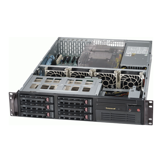
Chapter 6: Advanced Chassis Setup Chapter 6 Advanced Chassis Setup This chapter covers the steps required to install components and perform mainte- nance on the SC823T-653LPB chassis. For component installation, follow the steps in the order given to eliminate the most common problems encountered. If some steps are unnecessary, skip ahead to the step that follows. - Page 58 UPER ERVER 6027B-TLF User's Manual Unpacking The serverboard is shipped in antistatic packaging to avoid static damage. When unpacking the board, make sure the person handling it is static protected. Figure 6-1. Chassis: Front and Rear Views DVD-ROM Drive (optional) Control Panel SATA Drives (6) 5.25"...
-
Page 59: Control Panel
JF1 can be found in Chapter 5. System Fans Four 8-cm fans provide all the cooling needed for the SuperServer 6027B-TLF. It is very important that the chassis top cover is properly installed and making a good seal for the cooling air to circulate properly through the chassis and cool the components. -
Page 60: Drive Bay Installation/Removal
UPER ERVER 6027B-TLF User's Manual 4. If the system is already powered on, the fan will activate immediately upon being connected to its header on the serverboard. Figure 6-2. System Fan Removal Drive Bay Installation/Removal Accessing the Drive Bays You do not need to access the inside of the chassis to replace or swap SATA drives. Proceed to the next step for instructions. -
Page 61: Sata Drive Installation
Chapter 6: Advanced Chassis Setup Enterprise level hard disk drives are recommended for use in Supermicro chassis and servers. For information on recommended HDDs, visit the Supermicro Web site at http://www.supermicro.com/products/nfo/fi les/ storage/SAS-1-CompList-110909.pdf Figure 6-3. Mounting a Drive in a Carrier Use caution when working around the SATA backplane. - Page 62 UPER ERVER 6027B-TLF User's Manual Installing/Removing Hot-swap SATA Drives 1. Push the release button on the drive carrier. 2. Swing the handle fully out and use it to pull the drive carrier straight out (see Figure 6-4). Note: Your operating system must have RAID support to enable the hot-plug ca- pability of the drives.
-
Page 63: Installing A Component In The 5.25" Drive Bay
Chapter 6: Advanced Chassis Setup Installing a Component in the 5.25" Drive Bay A single 5.25" drive bay is located in the front of the chassis, making it easily acces- sible for installation and removal. This component is not hot-swappable, meaning system power must be turned off before installing and/or removing them. -
Page 64: Dvd-Rom Drive Installation
UPER ERVER 6027B-TLF User's Manual DVD-ROM Drive Installation The top cover of the chassis must be opened to gain full access to the DVD-ROM. The 6027B-TLF accomodates only slim DVD-ROM drives. Side mounting brakets are typically needed to mount a DVD-ROM drive in the 6027B-TLF server. Installing a DVD-ROM Drive Drives mount on rails and should "click"... -
Page 65: Power Supply Failure
Chapter 6: Advanced Chassis Setup Power Supply The SuperServer 6027B-TLF has a single 650 watt power supply. This power supply module has an auto-switching capability, which enables it to automatically sense and operate at a 100V to 240V input voltage. - Page 66 UPER ERVER 6027B-TLF User's Manual Notes 6-10...
-
Page 67: Chapter 7 Bios
Chapter 7: BIOS Chapter 7 BIOS Introduction This chapter describes the AMI BIOS Setup utility for the X9DBL-i/3/iF/3F. It also provides the instructions on how to navigate the AMI BIOS Setup utility screens. The AMI ROM BIOS is stored in a Flash EEPROM and can be easily updated. Starting BIOS Setup Utility To enter the AMI BIOS Setup utility screens, press the <Del>... -
Page 68: How To Change The Confi Guration Data
UPER ERVER 6027B-TLF User's Manual How To Change the Confi guration Data The confi guration data that determines the system parameters may be changed by entering the AMI BIOS Setup utility. This Setup utility can be accessed by pressing <Delete> at the appropriate time during system boot. Note: For AMI UEFI BIOS Recovery, please refer to the UEFI BIOS Re- covery User Guide posted @http://www.supermicro.com/support/manuals/. - Page 69 Chapter 7: BIOS The AMI BIOS main menu displays the following information: System Date/System Time Use this option to change the system time and date. Highlight System Time or System Date using the arrow keys. Enter new values through the keyboard and press <Enter>.
-
Page 70: Advanced Setup Confi Gurations
UPER ERVER 6027B-TLF User's Manual Advanced Setup Confi gurations Use the arrow keys to select Advanced Setup and press <Enter> to access the following submenu items. Boot Features Quiet Boot This feature allows the user to select bootup screen display between POST mes- sages and the OEM logo. - Page 71 Chapter 7: BIOS Interrupt 19 Capture Interrupt 19 is the software interrupt that handles the boot disk function. When this item is set to Enabled, the ROM BIOS of the host adaptors will "capture" Interrupt 19 at bootup and allow the drives that are attached to these host adaptors to function as bootable disks.
- Page 72 UPER ERVER 6027B-TLF User's Manual Socket 1 CPU Information/Socket 2 CPU Information This submenu displays the following information regarding the CPUs installed in Socket 1/ Socket 2. • Type of CPU • CPU Signature • Microcode Patch • CPU Stepping •...
- Page 73 Chapter 7: BIOS RTID (Record Types IDs) This feature displays the total number of Record Type IDs for local and remote pools. The options are Optimal and Alternate. Hyper-threading Select Enabled to support Intel Hyper-threading Technology to enhance CPU per- formance.
- Page 74 UPER ERVER 6027B-TLF User's Manual DCU IP Prefetcher Select Enabled for DCU (Data Cache Unit) IP Prefetcher support, which will prefetch IP addresses to improve network connectivity and system performance. The options are Enabled and Disabled. Intel® Virtualization Technology (Available when supported by the CPU) Select Enabled to support Intel Virtualization Technology, which will allow one platform to run multiple operating systems and applications in independent parti- tions, creating multiple "virtual"...
- Page 75 Chapter 7: BIOS CPU C6 Report (Available when Power Technology is set to Custom) Select Enabled to allow the BIOS to report the CPU C6 State (ACPI C3) to the operating system. During the CPU C6 State, the power to all cache is turned off.
-
Page 76: North Bridge
UPER ERVER 6027B-TLF User's Manual Short Duration Power Limit During Turbo Mode, the system may exceed the processors default power set- ting and exceed the Short Duration Power limit. By increasing this value, the processsor can provide better performance for short duration. This fi gure shows the period of time in during which short duration power (in watts) is maintained. - Page 77 Chapter 7: BIOS Port 1B Link Speed Select GEN1 to enable PCI-Exp Generation 1 support for Port 1B. Select GEN2 to enable PCI-Exp Generation 2 support for Port 1B. Select GEN3 to enable PCI-Exp Generation 3 support for Port 1B. The options are GEN1, GEN2, and GEN3.
- Page 78 UPER ERVER 6027B-TLF User's Manual Port 1A Link Speed Select GEN1 to enable PCI-Exp Generation 1 support for Port 1A. Select GEN2 to enable PCI-Exp Generation 2 support for Port 1A. Select GEN3 to enable PCI-Exp Generation 3 support for Port 1A. The options are GEN1, GEN2, and GEN3.
- Page 79 Chapter 7: BIOS Isoc Select Enabled to enable Isochronous support to meet QoS (Quality of Service) requirements. This feature is especially important for virtualization technology. The options are Enabled and Disabled. QPI (Quick Path Interconnect) Link Speed Mode Use this feature to select data transfer speed for QPI Link connections. The options are Fast and Slow.
- Page 80 UPER ERVER 6027B-TLF User's Manual Memory Mode When Independent is selected, all DIMMs are available to the operating system. When Mirroring is selected, the motherboard maintains two identical copies of all data in memory for data backup. When Lockstep is selected, the motherboard uses two areas of memory to run the same set of operations in parallel.
- Page 81 Chapter 7: BIOS Data Scrambling Select Enabled to enable data scrambling to ensure data security and integrity. The options are Disabled and Enabled. Device Tagging Select Enabled to support device tagging. The options are Disabled and En- abled. Thermal Throttling Throttling improves reliability and reduces power consumption in the proces- sor via automatic voltage control during processor idle states.
- Page 82 UPER ERVER 6027B-TLF User's Manual Port 60/64 Emulation Select Enabled to enable I/O port 60h/64h emulation support for the legacy USB keyboard so that it can be fully supported by the operating systems that does not recognize a USB device. The options are Disabled and Enabled. EHCI Hand-Off This item is for operating systems that do not support Enhanced Host Controller Interface (EHCI) hand-off.
- Page 83 Chapter 7: BIOS Port 0~5 Hot Plug Select Enabled to enable hot-plug support for a particular port, which will allow the user to change a hardware component or device without shutting down the system. The options are Enabled and Disabled. Staggered Spin Up Select Enabled to enable Staggered Spin-up support to prevent excessive power consumption caused by multiple HDDs spinning-up simultaneously.
- Page 84 UPER ERVER 6027B-TLF User's Manual PCI Latency Timer Use this feature to set the latency Timer of each PCI device installed on a PCI bus. Select 64 to set the PCI latency to 64 PCI clock cycles. The options are 32, 64, 96, 128, 160, 192, 224 and 248.
- Page 85 Chapter 7: BIOS Onboard LAN Option ROM Select Select iSCSI to use the iSCSI Option ROM to boot the computer using a network device. Select PXE (Preboot Execution Environment) to use an PXE Option ROM to boot the computer using a network device. The options are iSCSI and PXE. Load Onboard LAN1 Option ROM/Load Onboard LAN2 Option ROM Select Enabled to enable the onboard LAN1 Option ROM~LAN2 Option ROM.
-
Page 86: Serial Port Console Redirection
UPER ERVER 6027B-TLF User's Manual Serial Port 2 Confi guration Serial Port Select Enabled to enable a serial port specifi ed by the user. The options are En- abled and Disabled. Device Settings This item displays the settings of Serial Port 2. Change Settings This option specifi... - Page 87 Chapter 7: BIOS Terminal Type This feature allows the user to select the target terminal emulation type for Con- sole Redirection. Select VT100 to use the ASCII Character set. Select VT100+ to add color and function key support. Select ANSI to use the Extended ASCII Char- acter Set.
- Page 88 UPER ERVER 6027B-TLF User's Manual Recorder Mode Select Enabled to capture the data displayed on a terminal and send it as text messages to a remote server. The options are Disabled and Enabled. Resolution 100x31 Select Enabled for extended-terminal resolution support. The options are Dis- abled and Enabled.
-
Page 89: Acpi Settings
Chapter 7: BIOS Bits Per Second This item sets the transmission speed for a serial port used in Console Redirec- tion. Make sure that the same speed is used in the host computer and the client computer. A lower transmission speed may be required for long and busy lines. The options are 9600, 19200, 57600, and 115200 (bits per second). - Page 90 UPER ERVER 6027B-TLF User's Manual Trusted Computing (Available when a TPM device is detected by the BIOS) Confi guration TPM Support Select Enabled on this item and enable the TPM jumper on the motherboard to enable TPM support to improve data integrity and network security. The options are Enabled and Disabled.
- Page 91 Chapter 7: BIOS CPU: TXT (Trusted Execution Technology) Feature Chipset: TXT (Trusted Execution Technology) Feature Intel TXT (LT-SX) Confi guration This feature displays the following TXT confi guration setting. TXT (LT-SX) Support: This item indicates if the Intel TXT support is enabled or disabled.
-
Page 92: Event Logs
UPER ERVER 6027B-TLF User's Manual Event Logs Use this feature to confi gure Event Log settings. Change SMBIOS Event Log Settings This feature allows the user to confi gure SMBIOS Event settings. Enabling/Disabling Options SMBIOS Event Log Select Enabled to enable SMBIOS (System Management BIOS) Event Logging during system boot. - Page 93 Chapter 7: BIOS Erasing Settings Erase Event Log Select Enabled to erase the SMBIOS (System Management BIOS) Event Log, which is completed before an event logging is initialized upon system reboot. The options are No, Yes, next reset, and Yes, every reset. When Log is Full Select Erase Immediately to immediately erase SMBIOS error event logs that ex- ceed the limit when the SMBIOS event log is full.
-
Page 94: Ipmi
UPER ERVER 6027B-TLF User's Manual IPMI Use this feature to confi gure Intelligent Platform Management Interface (IPMI) settings. IPMI Firmware Revision This item indicates the IPMI fi rmware revision used in your system. IPMI Status This item indicates the status of the IPMI fi rmware installed in your system. System Event Log Enabling/Disabling Options SEL Components... - Page 95 Chapter 7: BIOS When SEL is Full This feature allows the user to decide what the BIOS should do when the system event log is full. Select Erase Immediately to erase all events in the log when the system event log is full. The options are Do Nothing and Erase Immediately. Custom EFI Logging Options Log EFI Status Codes Select Enabled to log EFI (Extensible Firmware Interface) Status Codes, Error...
-
Page 96: Boot
UPER ERVER 6027B-TLF User's Manual Gateway IP Address This item displays the Gateway IP address for this computer. This should be in decimal and in dotted quad form (i.e., 192.168.10.253). Boot This submenu allows the user to confi gure the following boot settings for the system. -
Page 97: Security
Chapter 7: BIOS Security This menu allows the user to confi gure the following security settings for the system. Administrator Password Use this feature to set the Administrator Password which is required to enter the BIOS setup utility. The length of the password should be from 3 characters to 20 characters long. -
Page 98: Save & Exit
UPER ERVER 6027B-TLF User's Manual Save & Exit This submenu allows the user to confi gure the Save and Exit settings for the system. Discard Changes and Exit Select this option to quit the BIOS Setup without making any permanent changes to the system confi... - Page 99 Chapter 7: BIOS Discard Changes Select this feature and press <Enter> to discard all the changes and return to the BIOS setup. When the dialog box appears, asking you if you want to load previ- ous values, select Yes to load the values previous saved, or select No to keep the changes you've made so far.
- Page 100 UPER ERVER 6027B-TLF User's Manual Notes 7-34...
-
Page 101: Appendix A Bios Error Beep Codes
Appendix A: BIOS Error Beep Codes Appendix A BIOS Error Beep Codes During the POST (Power-On Self-Test) routines, which are performed at each system boot, errors may occur. Non-fatal errors are those which, in most cases, allow the system to continue to boot. - Page 102 UPER ERVER 6027B-TLF User's Manual Notes...
-
Page 103: Appendix B System Specifi Cations
Appendix B: System Specifi cations Appendix B System Specifi cations Processors Single or dual Intel ® Xeon ® E5-2400 Series processor in LGA 1356 sockets Note: Please refer to our web site for a complete listing of supported processors. Chipset Intel C602 BIOS 64 Mb SPI AMI®... - Page 104 UPER ERVER 6027B-TLF User's Manual Weight Gross Weight: 42 lbs. (19.09 kg.) System Cooling Four 8-cm PWM fans System Input Requirements AC Input Voltage: 100-240V AC auto-range Rated Input Current: 8-5.2A (100-140V), 4.2-3.1A (180-240V) Rated Input Frequency: 50 to 60 Hz Power Supply Rated Output Power: 650W (Part# PWS-653-2H) Rated Output Voltages: +3.3V (25A), +5V (30A), +12V (49-54A), -12V (0.5A),...
- Page 105 Appendix B: System Specifi cations Safety: EN 60950/IEC 60950-Compliant, UL Listed (USA), CUL Listed (Canada), TUV Certifi ed (Germany), CE Marking (Europe) California Best Management Practices Regulations for Perchlorate Materials: This Perchlorate warning applies only to products containing CR (Manganese Dioxide) Lithium coin cells.
- Page 106 UPER ERVER 6027B-TLF User's Manual Notes...
Need help?
Do you have a question about the SUPERSERVER 6027B-TLF and is the answer not in the manual?
Questions and answers