Table of Contents
Advertisement
Quick Links
Advertisement
Table of Contents

Subscribe to Our Youtube Channel
Related Manuals for Supero SUPERSERVER 6027R-N3RF


Summary of Contents for Supero SUPERSERVER 6027R-N3RF
- Page 1 UPER ® SUPERSERVER 6027R-N3RF 6027R-WRF USER'S MANUAL Revision 1.0a...
- Page 2 This product, including software and documentation, is the property of Supermicro and/or its licensors, and is supplied only under a license. Any use or reproduction of this product is not allowed, except as expressly permitted by the terms of said license.
-
Page 3: About This Manual
Chapter 2: Server Installation This chapter describes the steps necessary to install the SuperServer 6027R-N3RF/WRF into a rack and check out the server confi guration prior to powering up the system. If your server was ordered without processor and memory components, this chapter will refer you to the appropriate sections of the manual for their installation. - Page 4 SUPERSERVER 6027R-N3RF/WRF USER'S MANUAL Chapter 6: Advanced Chassis Setup Refer to Chapter 6 for detailed information on the SC825TQ-R740WB server chassis. You should follow the procedures given in this chapter when installing, removing or reconfi guring SAS/SATA or peripheral drives and when replacing system power supply units and cooling fans.
- Page 5 Preface Notes...
-
Page 6: Table Of Contents
Overview ......................1-1 Serverboard Features ..................1-2 Processors ...................... 1-2 Memory ......................1-2 Serial ATA ....................... 1-2 SAS (6027R-N3RF Server Only) ..............1-2 Onboard Controllers/Ports ................1-3 Graphics Controller ..................1-3 Other Features ....................1-3 Server Chassis Features ................1-3 System Power .................... - Page 7 Table of Contents Installing the System into a Rack ..............2-4 Separating the Sections of the Rack Rails ............. 2-4 Installing the Inner Rail Extension ..............2-4 Outer Rack Rails ..................... 2-6 Checking the Serverboard Setup ..............2-8 Checking the Drive Bay Setup ..............2-10 Chapter 3 System Interface Overview ......................
- Page 8 SUPERSERVER 6027R-N3RF/WRF USER'S MANUAL Chapter 5 Advanced Serverboard Setup Handling the Serverboard ................5-1 Precautions ..................... 5-1 Unpacking ....................... 5-1 Processor and Heatsink Installation..............5-2 Installing a Passive CPU Heatsink ..............5-6 Removing the Heatsink ................... 5-7 Connecting Cables ..................5-8 Connecting Data Cables .................
- Page 9 SUPERSERVER 6027R-N3RF/WRF USER'S MANUAL Permanent and Optional Standoffs ............... 6-10 Power Supply ....................6-12 Power Supply Failure ..................6-12 Replacing the Power Distributor ..............6-13 Chapter 7 BIOS Introduction ...................... 7-1 Starting the Setup Utility ................. 7-1 Main Menu ...................... 7-1 System Time/System Date ................
- Page 10 SUPERSERVER 6027R-N3RF/WRF USER'S MANUAL Notes viii...
-
Page 11: Chapter 1 Introduction
Chapter 1 Introduction Overview The SuperServer 6027R-N3RF/WRF is a high-end server comprised of two main subsystems: the SC825TQ-R740WB 2U server chassis and the X9DRW-3F/iF dual processor serverboard. Please refer to our web site for information on operating systems that have been certifi ed for use with the system (www.supermicro.com). -
Page 12: Serverboard Features
SUPERSERVER 6027R-N3RF/WRF USER'S MANUAL Serverboard Features At the heart of the SuperServer 6027R-N3RF/WRF lies the X9DRW-3F/iF, a dual processor serverboard based on the Intel PCH 606/602 chipset. Below are the main features of the X9DRW-3F/iF. (See Figure 1-1 for a block diagram of the chipset). -
Page 13: Onboard Controllers/Ports
AC power loss recovery, virus protection and BIOS rescue. Server Chassis Features The SuperServer 6027R-N3RF/WRF is built upon the SC825TQ-R740WB chassis. Details on the chassis and on servicing procedures can be found in Chapter 6. The following is a general outline of the main features of the chassis. -
Page 14: Front Control Panel
SUPERSERVER 6027R-N3RF/WRF USER'S MANUAL Front Control Panel The control panel on the SuperServer 6027R-N3RF/WRF provides you with system monitoring and control. LEDs indicate system power, HDD activity, network activity, system overheat and power supply failure. A main power button and a system reset button are also included. - Page 15 Chapter 1: Introduction Figure 1-1. Intel PCH 606/602 Chipset: System Block Diagram Note: This is a general block diagram. Please see Chapter 5 for details. Right Slot PCIE 3.0x16 PE2 PE1 CPU Rear Socket 01 PROCESSOR CPU Front Socket 00 PROCESSOR BIOS P0PE3...
-
Page 16: Contacting Supermicro
SUPERSERVER 6027R-N3RF/WRF USER'S MANUAL Contacting Supermicro Headquarters Address: Super Micro Computer, Inc. 980 Rock Ave. San Jose, CA 95131 U.S.A. Tel: +1 (408) 503-8000 Fax: +1 (408) 503-8008 Email: marketing@supermicro.com (General Information) support@supermicro.com (Technical Support) Web Site: www.supermicro.com Europe Address: Super Micro Computer B.V. -
Page 17: Chapter 2 Server Installation
fi le a damage claim with the carrier who delivered it. Decide on a suitable location for the rack unit that will hold the SuperServer 6027R-N3RF/WRF. It should be situated in a clean, dust-free area that is well ventilated. Avoid areas where heat, electrical noise and electromagnetic fi elds are generated. -
Page 18: Choosing A Setup Location
SUPERSERVER 6027R-N3RF/WRF USER'S MANUAL Choosing a Setup Location • Leave enough clearance in front of the rack to enable you to open the front door completely (~25 inches) and approximately 30 inches of clearance in the back of the rack to allow for suffi cient airfl ow and ease in servicing. -
Page 19: Rack Mounting Considerations
Chapter 2: Server Installation Rack Mounting Considerations Warning! To prevent bodily injury when mounting or servicing this unit in a rack, you must take special precautions to ensure that the system remains stable. The following guidelines are provided to ensure your safety: •... -
Page 20: Reliable Ground
SUPERSERVER 6027R-N3RF/WRF USER'S MANUAL Reliable Ground A reliable ground must be maintained at all times. To ensure this, the rack itself should be grounded. Particular attention should be given to power supply connections other than the direct connections to the branch circuit (i.e. the use of power strips, etc.). - Page 21 Chapter 2: Server Installation Figure 2-1: Separating the Rack Rails Separating the Inner and Outer Rails Rail Assembly 1. Locate the rail assembly in the chassis packaging. 2. Extend the rail assembly by pulling it outward. Extending the Rails 3. Press the quick-release tab. 4.
-
Page 22: Outer Rack Rails
SUPERSERVER 6027R-N3RF/WRF USER'S MANUAL Outer Rack Rails Outer rails attach to the rack and hold the chassis in place. The outer rails for the SC825 chassis extend between 30 inches and 33 inches. Installing the Outer Rails to the Rack (Figure 2-2) 1. - Page 23 Chapter 2: Server Installation Figure 2-3. Installing the Rack Rails Note: The fi gure above is for illustrative purposes only. Always install servers to the bottom of the rack fi rst.
-
Page 24: Checking The Serverboard Setup
SUPERSERVER 6027R-N3RF/WRF USER'S MANUAL Checking the Serverboard Setup After you install the SuperServer 6027R-N3RF/WRF in the rack, you will need to open the unit to make sure the serverboard is properly installed and all the connections have been made. Accessing the inside of the System (Figure 2-4) 1. - Page 25 Chapter 2: Server Installation Figure 2-4. Accessing the Inside of the System...
-
Page 26: Checking The Drive Bay Setup
SUPERSERVER 6027R-N3RF/WRF USER'S MANUAL Checking the Drive Bay Setup Next, you should check to make sure the peripheral drives and the SAS/SATA drives have been properly installed and all connections have been made. Checking the Drives 1. All drives are accessable from the front of the server. For servicing the DVD- ROM, you will need to remove the top chassis cover. -
Page 27: Chapter 3 System Interface
System Interface Overview There are several LEDs on the control panel of the 6027R-N3RF/WRF server as well as others on the drive carriers to keep you constantly informed of the overall status of the system as well as the activity and health of specifi c components. There are also two buttons on the chassis control panel. -
Page 28: Control Panel Leds
SUPERSERVER 6027R-N3RF/WRF USER'S MANUAL Control Panel LEDs The control panel located on the front of the chassis has several LEDs. These LEDs provide you with critical information related to different parts of the system. This section explains what each LED indicates when illuminated and any corrective action you may need to take. -
Page 29: Hdd
Chapter 3: System Interface On the SUPERSERVER 6027R-N3RF/WRF, this LED indicates hard drive and/or DVD-ROM drive activity when fl ashing. Power Indicates power is being supplied to the system's power supply units. This LED should normally be illuminated when the system is operating. - Page 30 SUPERSERVER 6027R-N3RF/WRF USER'S MANUAL Notes...
-
Page 31: Chapter 4 Standardized Warning Statements For Ac Systems
Only certifi ed technicians should attempt to install or confi gure components. Read this appendix in its entirety before installing or confi guring components in the Supermicro chassis. These warnings may also be found on our web site at http://www.supermicro.com/ about/policies/safety_information.cfm. Warning Defi nition Warning! This warning symbol means danger. - Page 32 SUPERSERVER F627R2-FT+/FTPT+/F72+/F72PT+ USER'S MANUAL Warnung WICHTIGE SICHERHEITSHINWEISE Dieses Warnsymbol bedeutet Gefahr. Sie befi nden sich in einer Situation, die zu Verletzungen führen kann. Machen Sie sich vor der Arbeit mit Geräten mit den Gefahren elektrischer Schaltungen und den üblichen Verfahren zur Vorbeugung vor Unfällen vertraut.
- Page 33 Warning Statements for AC Systems ﺟﺴﺪﻳﺔ ﺍﺻﺎﺑﺔ ﺗﺘﺴﺒﺐ ﻓﻲ ﺣﺎﻟﺔ ﻳﻤﻜﻦ ﺃﻥ ﺍﻧﻚ ﻓﻲ ﺧﻄﺮ ﻳﻌﻨﻲ ﻫﺬﺍ ﺍﻟﺮﻣﺰ !ﺗﺤﺬﻳﺮ ﺍﻟﺪﻭﺍﺋﺮ ﺑﺎﻟﻤﺨﺎﻁﺮ ﺍﻟﻨﺎﺟﻤﺔ ﻋﻦ ﻦ ﻋﻠﻰ ﻋﻠﻢ ، ﻛ ﻣﻌﺪﺍﺕ ﺗﻌﻤﻞ ﻋﻠﻰ ﺃﻱ ﻗﺒﻞ ﺃﻥ ﺍﻟﻜﻬﺮﺑﺎﺋﻴﺔ ﺣﻮﺍﺩﺙ ﺃﻱ ﻭﻗﻮﻉ ﻤﻨﻊ ﻟ ﺍﻟﻮﻗﺎﺋﻴﺔ...
-
Page 34: Installation Instructions
SUPERSERVER F627R2-FT+/FTPT+/F72+/F72PT+ USER'S MANUAL Installation Instructions Warning! Read the installation instructions before connecting the system to the power source. 警告 将此系统连接电源前,请先阅读安装说明。 警告 將系統與電源連接前,請先閱讀安裝說明。 Warnung Vor dem Anschließen des Systems an die Stromquelle die Installationsanweisungen lesen. ¡Advertencia! Lea las instrucciones de instalación antes de conectar el sistema a la red de alimentación. -
Page 35: Circuit Breaker
Chapter 4: Warning Statements for AC Systems Circuit Breaker Warning! This product relies on the building's installation for short-circuit (overcurrent) protection. Ensure that the protective device is rated not greater than: 250 V, 20 A. 警告 此产品的短路(过载电流)保护由建筑物的供电系统提供,确保短路保护设备的额定电 流不大于250V,20A。 警告 此產品的短路(過載電流)保護由建築物的供電系統提供,確保短路保護設備的額定電 流不大於250V,20A。... -
Page 36: Power Disconnection Warning
SUPERSERVER F627R2-FT+/FTPT+/F72+/F72PT+ USER'S MANUAL ﻓﻲ ﺍﻟﺘﻲ ﺗﻢ ﺗﺜﺒﻴﺘﻬﺎ ﻣﻦ ﺍﻟﺪﻭﺍﺋﺮﺍﻟﻘﺼﻴﺮﺓ ﺍﻟﺤﻤﺎﻳﺔ ﻣﻌﺪﺍﺕ ﻳﻌﺘﻤﺪ ﻋﻠﻰ ﻫﺬﺍ ﺍﻟﻤﻨﺘﺞ ﺍﻟﻤﺒﻨﻰ ﺃﻛﺜﺮ ﻣﻦ ﻟﻴﺲ ﻮﻗﺎﺋﻲ ﺍﻟ ﺍﻟﺠﻬﺎﺯ ﺗﻘﻴﻴﻢ ﺃﻥ ﺗﺄﻛﺪ ﻣﻦ 20A, 250V Waarschuwing Dit product is afhankelijk van de kortsluitbeveiliging (overspanning) van uw electrische installatie. - Page 37 Chapter 4: Warning Statements for AC Systems Warnung Das System muss von allen Quellen der Energie und vom Netzanschlusskabel getrennt sein, das von den Spg.Versorgungsteilmodulen entfernt wird, bevor es auf den Chassisinnenraum zurückgreift, um Systemsbestandteile anzubringen oder zu entfernen. ¡Advertencia! El sistema debe ser disconnected de todas las fuentes de energía y del cable eléctrico quitado de los módulos de fuente de alimentación antes de tener acceso el interior del chasis para instalar o para quitar componentes de sistema.
-
Page 38: Equipment Installation
SUPERSERVER F627R2-FT+/FTPT+/F72+/F72PT+ USER'S MANUAL Equipment Installation Warning! Only trained and qualifi ed personnel should be allowed to install, replace, or service this equipment. 警告 只有经过培训且具有资格的人员才能进行此设备的安装、更换和维修。 警告 只有經過受訓且具資格人員才可安裝、更換與維修此設備。 Warnung Das Installieren, Ersetzen oder Bedienen dieser Ausrüstung sollte nur geschultem, qualifi ziertem Personal gestattet werden. ¡Advertencia! Solamente el personal califi... -
Page 39: Restricted Area
Chapter 4: Warning Statements for AC Systems Waarschuwing Deze apparatuur mag alleen worden geïnstalleerd, vervangen of hersteld door geschoold en gekwalifi ceerd personeel. Restricted Area Warning! This unit is intended for installation in restricted access areas. A restricted access area can be accessed only through the use of a special tool, lock and key, or other means of security. -
Page 40: Battery Handling
SUPERSERVER F627R2-FT+/FTPT+/F72+/F72PT+ USER'S MANUAL אזור עם גישה מוגבלת !אזהרה יש להתקין את היחידה באזורים שיש בהם הגבלת גישה. הגישה ניתנת בעזרת .('כלי אבטחה בלבד )מפתח, מנעול וכד ﻣﺤﻈﻮﺭﺓ ﻣﻨﺎﻁﻖ ﻟﺘﺮﻛﻴﺒﻬﺎ ﻓﻲ ﻫﺬﻩ ﺍﻟﻮﺣﺪﺓ ﺗﺨﺼﻴﺺ ﺗﻢ ،ﺃﺩﺍﺓ ﺧﺎﺻﺔ ﻣﻦ ﺧﻼﻝ ﺍﺳﺘﺨﺪﺍﻡ ﻓﻘﻂ... - Page 41 Chapter 4: Warning Statements for AC Systems Warnung Bei Einsetzen einer falschen Batterie besteht Explosionsgefahr. Ersetzen Sie die Batterie nur durch den gleichen oder vom Hersteller empfohlenen Batterietyp. Entsorgen Sie die benutzten Batterien nach den Anweisungen des Herstellers. Attention Danger d'explosion si la pile n'est pas remplacée correctement. Ne la remplacer que par une pile de type semblable ou équivalent, recommandée par le fabricant.
-
Page 42: Redundant Power Supplies
SUPERSERVER F627R2-FT+/FTPT+/F72+/F72PT+ USER'S MANUAL Redundant Power Supplies Warning! This unit might have more than one power supply connection. All connections must be removed to de-energize the unit. 警告 此部件连接的电源可能不止一个,必须将所有电源断开才能停止给该部件供电。 警告 此裝置連接的電源可能不只一個,必須切斷所有電源才能停止對該裝置的供電。 Warnung Dieses Gerät kann mehr als eine Stromzufuhr haben. Um sicherzustellen, dass der Einheit kein trom zugeführt wird, müssen alle Verbindungen entfernt werden. -
Page 43: Backplane Voltage
Chapter 4: Warning Statements for AC Systems ﺍﻣﺪﺍﺩ ﺍﻟﻄﺎﻗﺔ ﺑﻮﺣﺪﺍﺕ ﻋﺪﺓ ﺍﺗﺼﺎﻻﺕ ﺠﻬﺎﺯ ﺍﻟ ﻳﻜﻮﻥ ﻟﻬﺬﺍ ﻗﺪ ﺍﻟﻜﻬﺮﺑﺎء ﻋﻦ ﻮﺣﺪﺓ ﺍﻟ ﻟﻌﺰﻝ ﻛﺎﻓﺔ ﺍﻻﺗﺼﺎﻻﺕ ﻳﺠﺐ ﺇﺯﺍﻟﺔ Waarschuwing Deze eenheid kan meer dan één stroomtoevoeraansluiting bevatten. Alle aansluitingen dienen verwijderd te worden om het apparaat stroomloos te maken. Backplane Voltage Warning! Hazardous voltage or energy is present on the backplane when the system is... -
Page 44: Comply With Local And National Electrical Codes
SUPERSERVER F627R2-FT+/FTPT+/F72+/F72PT+ USER'S MANUAL Attention Lorsque le système est en fonctionnement, des tensions électriques circulent sur le fond de panier. Prendre des précautions lors de la maintenance. מתח בפנל האחורי !הרה אז קיימת סכנת מתח בפנל האחורי בזמן תפעול המערכת. יש להיזהר במהלך .העבודה... -
Page 45: Product Disposal
Chapter 4: Warning Statements for AC Systems ¡Advertencia! La instalacion del equipo debe cumplir con las normas de electricidad locales y nacionales.Attention L'équipement doit être installé conformément aux normes électriques nationales et locales. תיאום חוקי החשמל הארצי !אזהרה הציוד חייבת להיות תואמת לחוקי החשמל המקומיים והארציים התקנת... -
Page 46: Hot Swap Fan Warning
SUPERSERVER F627R2-FT+/FTPT+/F72+/F72PT+ USER'S MANUAL Warnung Die Entsorgung dieses Produkts sollte gemäß allen Bestimmungen und Gesetzen des Landes erfolgen. ¡Advertencia! Al deshacerse por completo de este producto debe seguir todas las leyes y reglamentos nacionales. Attention La mise au rebut ou le recyclage de ce produit sont généralement soumis à des lois et/ou directives de respect de l'environnement. - Page 47 Chapter 4: Warning Statements for AC Systems 当您从机架移除风扇装置,风扇可能仍在转动。小心不要将手指、螺丝起子和其他 物品太靠近风扇 警告 當您從機架移除風扇裝置,風扇可能仍在轉動。小心不要將手指、螺絲起子和其他 物品太靠近風扇。 Warnung Die Lüfter drehen sich u. U. noch, wenn die Lüfterbaugruppe aus dem Chassis genommen wird. Halten Sie Finger, Schraubendreher und andere Gegenstände von den Öffnungen des Lüftergehäuses entfernt. ¡Advertencia! Los ventiladores podran dar vuelta cuando usted quite ell montaje del ventilador del chasis.
-
Page 48: Power Cable And Ac Adapter
fi re. Electrical Appliance and Material Safety Law prohibits the use of UL or CSA -certifi ed cables (that have UL/CSA shown on the code) for any other electrical devices than products designated by Supermicro only. 警告... - Page 49 Appareils électroménagers et de loi sur la sécurité Matériel interdit l'utilisation de UL ou CSA câbles certifi és qui ont UL ou CSA indiqué sur le code pour tous les autres appareils électriques que les produits désignés par Supermicro seulement.
- Page 50 Elektrisch apparaat en veiligheidsinformatiebladen wet verbiedt het gebruik van UL of CSA gecertifi ceerde kabels die UL of CSA die op de code voor andere elektrische apparaten dan de producten die door Supermicro alleen.
-
Page 51: Chapter 5 Advanced Serverboard Setup
Chapter 5: Advanced Serverboard Setup Chapter 5 Advanced Serverboard Setup This chapter covers the steps required to install processors and heatsinks to the X9DRW-3F/iF serverboard, connect the data and power cables and install add-on cards. All serverboard jumpers and connections are described and a layout and quick reference chart are included in this chapter. -
Page 52: Processor And Heatsink Installation
CPU socket cap is in place and none of the socket pins are bent; otherwise, contact your retailer immediately. Refer to the Supermicro website for updates on CPU support. Installing the LGA2011 Processor 1. There are two load levers on the LGA2011 socket. To open the socket cover, fi... - Page 53 Chapter 5: Advanced Serverboard Setup 2. Press the second load lever labeled 'Close 1st' to release the load plate that covers the CPU socket from its locking position. Press down on Load the Lever Pull lever away labeled 'Close 1st' from the socket 3.
- Page 54 SUPERSERVER 6027R-N3RF/WRF USER'S MANUAL 5. Use your thumb and index fi nger to hold the CPU on its edges. Align the CPU keys, which are semi-circle cutouts, against the socket keys. Socket Keys CPU Keys 6. Once they are aligned, carefully lower the CPU straight down into the socket.
- Page 55 Chapter 5: Advanced Serverboard Setup 7. With the CPU inside the socket, inspect the four corners of the CPU to make sure that the CPU is properly installed. 8. Close the load plate with the CPU inside the socket. Lock the lever labeled 'Close 1st' fi...
-
Page 56: Installing A Passive Cpu Heatsink
SUPERSERVER 6027R-N3RF/WRF USER'S MANUAL Installing a Passive CPU Heatsink 1. Do not apply any thermal grease to the heatsink or the CPU die -- the required amount has already been applied. 2. Place the heatsink on top of the CPU so that the four mounting holes are aligned with those on the Motherboard's and the Heatsink Bracket underneath. -
Page 57: Removing The Heatsink
Chapter 5: Advanced Serverboard Setup Removing the Heatsink Caution: We do not recommend that the CPU or the heatsink be removed. However, if you do need to uninstall the heatsink, please follow the instructions below to uninstall the heatsink to prevent damage done to the CPU or the CPU socket. 1. -
Page 58: Connecting Cables
See the serverboard layout diagram in this chapter for connector locations. • • One (1) Control Panel cable (JF1, see next page) • • Two (2) SAS connection cables (for 6027R-N3RF server only) • • Two (2) AOC SAS connection cables(for 6027R-WRF server only) Connecting Power Cables The X9DRW-3F/iF has a 24-pin primary power supply connector designated "JPW1"... -
Page 59: I/O Ports
Chapter 5: Advanced Serverboard Setup Figure 5-1. Front Control Panel Header Pins (JF1) Ground x (key) x (key) FP PWRLED 3.3V HDD LED ID_UID_SW/3.3V Stby NIC1 Link LED NIC1 Activity LED NIC2 Link LED NIC2 Activity LED Blue+ (OHFan Fail/ PWR Fail/UID LED Red+ (Blue LED Cathode) Ground... -
Page 60: Installing Memory
SUPERSERVER 6027R-N3RF/WRF USER'S MANUAL Installing Memory Caution! Exercise extreme care when installing or removing DIMM modules to prevent any possible damage. Memory Support T h e X 9 D R W - 3 F / i F s u p p o r t s u p t o 5 1 2 G B o f r e g i s t e r e d E C C 1GB, 2GB, 4GB, 8GB, 16GB and 32GB size SDRAM in sixteen (16) DIMM slots of up to DDR3 1600/1333/1066/800 MHz speed. - Page 61 Chapter 5: Advanced Serverboard Setup Processors and their Corresponding Memory Modules CPU# Corresponding DIMM Modules CPU 1 DIMMA1 DIMMA2 DIMMB1 DIMMB2 DIMMC1 DIMMC2 DIMMD1 DIMMD2 CPU2 DIMME1 DIMME2 DIMMF1 DIMMF2 DIMMG1 DIMMG2 DIMMH1 DIMMH2 Processor and Memory Module Population Number of CPU and Memory Population Confi...
-
Page 62: Adding Pci Expansion Cards
SUPERSERVER 6027R-N3RF/WRF USER'S MANUAL LRDIMM Support on the Intel E5-2600 Series Processor Platform DIMMs Populated LRDIMM Type POR Speeds (in Ranks per DIMM per DDR Channel (Load Reduced MHz) (Any Combination) DIMM) LR ECC DDR3 1066, 1333 LR ECC DDR3... -
Page 63: Serverboard Details
Chapter 5: Advanced Serverboard Setup Serverboard Details Figure 5-4. X9DRW-3F/iF Serverboard Layout (not drawn to scale) COM1 USB0/1 JUIDB CTRL LAN1 LAN2 USB2/3 JPW4 IPMI-LAN CPU2 COM2 X9DRW-3F/iF Rev.1.02 CTRL JPW3 JI2C1 JVRM_I2C1 JPG1 BIOS JVRM_I2C2 CPU1 JPW2 JBT1 JBAT1 SATA/ SCU0~3 SATA/SCU4~7... -
Page 64: X9Drw-3F/If Quick Reference
SUPERSERVER 6027R-N3RF/WRF USER'S MANUAL X9DRW-3F/iF Quick Reference Jumper Description Default Setting JBT1 Clear CMOS See Chapter 3 JI2C1/JI2C2 SMB to PCI-E Slots Open (Normal) JPB1 BMC Enable Pins 1-2 (Enabled) JPG1 VGA Enable Pins 1-2 (Enabled) JPL1 LAN1/LAN2 Enable Pins 1-2 (Enabled) - Page 65 Chapter 5: Advanced Serverboard Setup Connector Description COM1/COM2 Backplane COM Port1/Front Accessible COM2 Header FAN1~4,FANA, FANB CPU/System Fan Headers I-SATA 0~5 Intel PCH SATA Connectors 0~5 JBAT1 Onboard Battery (See Chpt. 4 for Used Battery Disposal) Speaker/Power LED Connector (Pins 1~3: PWR LED, Pins 6~7: Onboard Buzzer/Pins 4~7: External Speaker) Front Panel Control Header JIPMB1...
-
Page 66: Connector Defi Nitions
SUPERSERVER 6027R-N3RF/WRF USER'S MANUAL Caution! To prevent damage to the power supply or motherboard, please use a power supply that contains a 24-pin, two 8-pin and one 4-pin power connectors. Be sure to connect these power supply connectors to the 24-pin power connector (JPW1), the two 8-pin power connectors (JPW2, JPW3) and the one 4-pin power connector (JPW4) on the motherboard. - Page 67 Chapter 5: Advanced Serverboard Setup PW_ON Connector Power Button Pin Defi nitions The Power Button connection is (JF1) located on pins 1 and 2 of JF1. Pin# Defi nition Momentarily contacting both pins will PW_ON power on/off the system. This button Ground can also be confi...
- Page 68 SUPERSERVER 6027R-N3RF/WRF USER'S MANUAL NIC1 (LAN1) LED NIC1 LED Pin Defi nitions (JF1) The NIC (Network Interface Controller) Pin# Defi nition LED connections for GLAN port 1 are NIC 2 Activity LED located on pins 11 and 12 of JF1, and...
- Page 69 Chapter 5: Advanced Serverboard Setup Universal Serial Bus (USB) FP USB (4/5) Pin Defi nitions Four Universal Serial Bus ports (USB USB 4, 8,10, 6, 7 USB 5, 9, 11 0/1, 2/3) are located on the I/O back Pin# Defi nition Pin# Defi...
- Page 70 SUPERSERVER 6027R-N3RF/WRF USER'S MANUAL Serial Ports Serial Port Pin Defi nitions (COM1/COM2) Two COM connections (COM1 & Pin# Defi nition Pin# Defi nition COM2) are located on the motherboard. COM1 is located on the Backplane I/O panel. COM2, located next to Front Accessible USB 4/5, is used to provide front access serial support.
- Page 71 Blue+ (OH/Fan Fail/ information on IPMI, please refer to Red+ (Blue LED Cathode) PWR FaiL/UID LED) the IPMI User's Guide posted on our Power Fail LED 3.3V Website @http://www.supermicro. Reset Reset Button Ground com. Power Button Ground Internal Speaker Internal Buzzer (SP1) Pin Defi...
- Page 72 SUPERSERVER 6027R-N3RF/WRF USER'S MANUAL Overheat LED/Fan Fail Overheat LED Pin Defi nitions The JOH1 header is used to connect (JOH1) an LED indicator to provide warnings Pin# Defi nition of chassis overheating and fan failure. This LED will blink when a fan failure OH Active occurs.
- Page 73 Chapter 5: Advanced Serverboard Setup IPMB IPMB Header Pin Defi nitions A System Management Bus header for (JIPMB1) IPMI 2.0 is located at JIPMB1. Connect Pin# Defi nition the appropriate cable here to use the Data IPMB I C connection on your system. Ground Clock No Connection...
- Page 74 SUPERSERVER 6027R-N3RF/WRF USER'S MANUAL Chassis Intrusion Chassis Intrusion Pin Defi nitions A Chassis Intrusion header is located (JL1) at JL1 on the motherboard. Attach an Pin# Defi nition appropriate cable from the chassis to Intrusion Input inform you of a chassis intrusion when Ground the chassis is opened.
-
Page 75: Jumper Settings
Chapter 5: Advanced Serverboard Setup Jumper Settings Connector Pins Explanation of Jumpers To modify the operation of the Jumper motherboard, jumpers can be used to choose between optional settings. Jumpers create shorts between two Setting pins to change the function of the connector. - Page 76 SUPERSERVER 6027R-N3RF/WRF USER'S MANUAL Watch Dog Enable/Disable Watch Dog Enable/Disable Jumper Settings (JWD) Watch Dog (JWD1) is a system moni- Jumper Setting Defi nition tor that can reboot the system when Pins 1-2 Reset a software application hangs. Close Pins 2-3 Pins 1-2 to reset the system if an ap- plication hangs.
-
Page 77: 5-10 Onboard Indicators
Chapter 5: Advanced Serverboard Setup 5-10 Onboard Indicators GLAN LEDs GLAN LED Link Speed Activity There are two LAN ports (LAN1/2) on the motherboard. Each Ethernet LAN port has two LEDs. The Yellow LED GLAN Activity Indicator on the right indicates connection and (Right) LED Settings activity. -
Page 78: 5-11 Sata/Sas Drive Connections
SUPERSERVER 6027R-N3RF/WRF USER'S MANUAL Onboard Power LED Onboard PWR LED Indicator LED Settings (LE1) An Onboard Power LED is located LED Color Defi nition at LE1 on the motherboard. When System Off (PWR cable not this LED is on, the system is on. Be... -
Page 79: 5-12 Installing Software
Chapter 5: Advanced Serverboard Setup 5-12 Installing Software The Supermicro ftp site contains drivers and utilities for your system at ftp://ftp. supermicro.com. Some of these must be installed, such as the chipset driver. After accessing the ftp site, go into the CDR_Images directory and locate the ISO fi... - Page 80 SUPERSERVER 6027R-N3RF/WRF USER'S MANUAL Note: Click the icons showing a hand writing on paper to view the readme fi les for each item. Click the computer icons to the right of these items to install each item (from top to the bottom) one at a time. After installing each item, you must re-boot the system before moving on to the next item on the list.
-
Page 81: Superdoctor Iii
Chapter 5: Advanced Serverboard Setup Figure 5-8. Supero Doctor III Interface Display Screen (Remote Control) Note: The SuperDoctor III program and User’s Manual can be downloaded from the Supermicro web site at http://www.supermicro.com/products/accessories/software/ SuperDoctorIII.cfm. For Linux, we recommend that you use the SuperDoctor II application instead. -
Page 82: 5-13 Serverboard Battery
SUPERSERVER 6027R-N3RF/WRF USER'S MANUAL 5-13 Serverboard Battery Caution: There is a danger of explosion if the onboard battery is installed upside down, which will reverse its polarites (see Figure 5-5). This battery must be replaced only with the same or an equivalent type recommended by the manufacturer (CR2032). -
Page 83: Chapter 6 Advanced Chassis Setup
Chapter 6: Advanced Chassis Setup Chapter 6 Advanced Chassis Setup This chapter covers the steps required to install components and perform maintenance on the SC825TQ-R740WB chassis. For component installation, follow the steps in the order given to eliminate the most common problems encountered. If some steps are unnecessary, skip ahead to the step that follows. -
Page 84: Control Panel
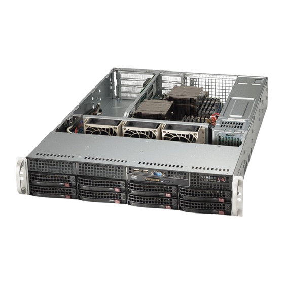
SUPERSERVER 6027R-N3RF/WRF USER'S MANUAL Figure 6-1. Front and Rear Chassis Views 3.5" Drive Bays (2) USB Ports (2) COM Port Slim DVD-ROM Drive (Optional) (Optional) (Optional) Control Panel SATA Drives (8) System Reset Main Power IPMI LAN Keyboard/Mouse Port 4 Standard Size PCI Slots... -
Page 85: Removing The Chassis Cover
Chapter 6: Advanced Chassis Setup Removing the Chassis Cover Removing the Chassis Cover 1. Remove the two screws on each side of the cover, which secure the cover to the chassis. 2. Press the release tabs to remove the cover from the locked position. Press both tabs at the same time. -
Page 86: System Fans
SUPERSERVER 6027R-N3RF/WRF USER'S MANUAL System Fans Three 8-cm heavy duty fans provide cooling for the chassis. These fans circulate air through the chassis as a means of lowering the chassis internal temperature. Figure 6-3: System Fan Release Tab Replacing a System Fan 1. -
Page 87: Installing The Air Shroud
Note that if a 16 DIMM (13.68" x 13") motherboard is used, it is necessary to use the optional MCP-310-82502-0N air shroud. For ordering information, visit the Supermicro website at www.supermicro.com and click on the Where to Buy link. -
Page 88: Drive Bay Installation/Removal
Supermicro's web site for additional inmformation at http://www.supermicro.com/support/manuals/ Warning: Enterprise level hard disk drives are recommended for use in Supermicro chassis and servers. For information on recommended HDDs, visit the Supermicro Web site at http://www.supermicro.com/products/nfo/fi les/ storage/SAS-CompList.pdf... -
Page 89: Sas/Sata Drive Installation
Chapter 6: Advanced Chassis Setup SAS/SATA Drive Installation These drives are mounted in carriers to simplify their installation and removal from the chassis. The carriers also help promote proper airfl ow for the drives. For this reason, even empty carriers without hard drives installed must remain in the chassis. Caution: Use caution when working around the backplane. - Page 90 SUPERSERVER 6027R-N3RF/WRF USER'S MANUAL Installing a Hard Drive to the Hard Drive Carrier 1. Remove the screws securing the dummy drive to the carrier. Figure 6-8: Chassis Drive Carrier Dummy Drive Drive Carrier Figure 6-9: Removing Dummy Drive from Carrier 2.
- Page 91 Chapter 6: Advanced Chassis Setup 4. Secure the hard drive by tightening all six screws. Figure 6-10: Removing the Hard Drive SAS/SATA Hard Drive Drive Carrier 5. Replace the drive carrier into the chassis bay, making sure that the drive carrier handle is completely closed.
-
Page 92: Installing The Motherboard
SUPERSERVER 6027R-N3RF/WRF USER'S MANUAL Installing the Motherboard I/O Shield The I/O shield holds the motherboard ports in place. Install the I/O shield before you install the motherboard. Installing the I/O Shield Installing the I/O Shield 1. Review the documentation that came with your motherboard. Become familiar with component placement, requirements, and precautions. - Page 93 Chapter 6: Advanced Chassis Setup Installing the Motherboard 1. Review the documentation that came with your motherboard. Become familiar with component placement, requirements, precautions, and cable connections. 2. Open the chassis cover. 3. As required by your motherboard, install standoffs in any areas that do not have a permanent standoff.
-
Page 94: Power Supply
SUPERSERVER 6027R-N3RF/WRF USER'S MANUAL Power Supply The SuperServer 6027R-N3RF/WRF has a 740 Watt redundant power supply consisting of two power modules. Each power supply module has an auto-switching capability, which enables it to automatically sense and operate at a 100V - 240V input voltage. -
Page 95: Replacing The Power Distributor
Chapter 6: Advanced Chassis Setup Figure 6-14: Removing the Power Supply Release Tab Replacing the Power Distributor Redundant server chassis that are 2U or greater require a power distributor. The power distributor provides failover and power supply redundancy. In the unlikely event you must replace the power distributor, do following 1. - Page 96 SUPERSERVER 6027R-N3RF/WRF USER'S MANUAL 7. Reconnect all the power cables, replace the power supply, and insert the plug into the wall. Figure 6-15: Replacing the Power Distributor 6-14...
-
Page 97: Chapter 7 Bios
Introduction This chapter describes the AMI BIOS Setup Utility for the SUPERSERVER 6027R-N3RF/WRF. The AMI ROM BIOS is stored in a Flash EEPROM and can be easily updated. This chapter describes the basic navigation of the AMI BIOS Setup Utility setup screens. -
Page 98: System Time/System Date
SUPERSERVER 6027R-N3RF/WRF USER'S MANUAL System Time/System Date You can edit this fi eld to change the system time and date. Highlight System Time or System Date using the <Arrow> keys. Enter new values through the keyboard. Press the <Tab> key or the <Arrow> keys to move between fi elds. The date must be entered in DAY/MM/DD/YYYY format. - Page 99 Chapter 7: BIOS not capture Interrupt 19, and the drives attached to these adaptors will not function as bootable devices. The options are Enabled and Disabled. Power Confi guration Watch Dog Function If enabled, the Watch Dog timer will allow the system to reboot when it is inactive for more than 5 minutes.
- Page 100 SUPERSERVER 6027R-N3RF/WRF USER'S MANUAL CPU Confi guration This submenu displays the information of the CPU as detected by the BIOS. It also allows the user to confi gure the CPU settings. Socket 1 CPU Information/Socket 2 CPU Information This submenu displays the following information regarding the CPUs installed in Socket 1/ Socket 2.
- Page 101 Chapter 7: BIOS Active Processor Cores Set to Enabled to use a processor's second core and above. (Please refer to Intel's website for more information.) The options are All, 1, 2, and 4. Limit CPUID Maximum This feature allows the user to set the maximum CPU ID value. Enable this function to boot the legacy operating systems that cannot support processors with extended CPUID functions.
- Page 102 SUPERSERVER 6027R-N3RF/WRF USER'S MANUAL Intel® Virtualization Technology (Available when supported by the CPU) Select Enabled to support Intel Virtualization Technology, which will allow one platform to run multiple operating systems and applications in independent partitions, creating multiple "virtual" systems in one physical computer. The options are Enabled and Disabled.
- Page 103 Chapter 7: BIOS CPU C6 Report (Available when Power Technology is set to Custom) Select Enabled to allow the BIOS to report the CPU C6 State (ACPI C3) to the operating system. During the CPU C6 State, the power to all cache is turned off.
-
Page 104: North Bridge
SUPERSERVER 6027R-N3RF/WRF USER'S MANUAL Chipset Confi guration North Bridge This feature allows the user to confi gure the settings for the Intel North Bridge. Integrated IO Confi guration Intel VT-d Select Enabled to enable Intel Virtualization Technology support for Direct I/O VT-d by reporting the I/O device assignments to the VWM (Virtual Working Memory) through the DMAR ACPI Tables. - Page 105 Chapter 7: BIOS QPI Confi guration Current QPI Link This item displays the current status of the QPI Link. Current QPI Frequency This item displays the frequency of the QPI Link. Isoc Select Enabled to enable Isochronous support to meet QoS (Quality of Service) requirements.
-
Page 106: Dimm Information
SUPERSERVER 6027R-N3RF/WRF USER'S MANUAL DIMM Information The status of the memory modules specifi ed below will be displayed as detected by the BIOS. CPU Socket 1 DIMM Information P1-DIMMA1/P1-DIMMB1/P1-DIMMC1/P1-DIMMD1/P1-DIMMA2/P1-DIMMB2/ P1-DIMMC2/P1-DIMMD2 CPU Socket 2 DIMM Information P2-DIMME1/P2-DIMMF1/P2-DIMMG1/P2-DIMMH1/P2-DIMME2/P2-DIMMF2/ P2-DIMMG2/P2-DIMMH2 Memory Mode When Independent is selected, all DIMMs are available to the operating system. - Page 107 Chapter 7: BIOS Patrol Scrub Patrol Scrubbing is a process that allows the CPU to correct correctable memory errors detected on a memory module and send the correction to the requestor (the original source). When this item is set to Enabled, the IO hub will read and write back one cache line every 16K cycles, if there is no delay caused by internal processing.
- Page 108 SUPERSERVER 6027R-N3RF/WRF USER'S MANUAL South Bridge Confi guration This feature allows the user to confi gure the settings for the Intel PCH chip. PCH Information This feature displays the following PCH information. Name: This item displays the name of the PCH chip.
- Page 109 Chapter 7: BIOS SATA Confi guration When this submenu is selected, the AMI BIOS automatically detects the presence of IDE or SATA devices and displays the following items. SATA Port0~SATA Port5: The AMI BIOS displays the status of each SATA port as detected by the BIOS. SATA Mode Use this feature to confi...
- Page 110 SUPERSERVER 6027R-N3RF/WRF USER'S MANUAL Port 0~5 Hot Plug Select Enabled to enable hot-plug support for the particular port. The options are Enabled and Disabled. SCU (Storage Control Unit) Confi guration Storage Controller Unit Select Enabled to enable PCH SCU storage devices. The options are Disabled and Enabled.
- Page 111 Chapter 7: BIOS Maximum Payload Select Auto to allow the system BIOS to automatically set the maximum payload value for a PCI-E device to enhance system performance. The options are Auto, 128 Bytes, 256 Bytes, 512 Bytes, 1024 Bytes, 2048 Bytes, and 4096 Bytes. Maximum Read Request Select Auto to allow the system BIOS to automatically set the maximum Read Request size for a PCI-E device to enhance system performance.
- Page 112 SUPERSERVER 6027R-N3RF/WRF USER'S MANUAL Super IO Confi guration Super IO Chip: This item displays the Super IO chip used in the motherboard. Serial Port 1 Confi guration Serial Port Select Enabled to enable a serial port specifi ed by the user. The options are Enabled and Disabled.
-
Page 113: Serial Port Console Redirection
Chapter 7: BIOS Serial Port Console Redirection • COM 1 and SOL/COM 2 These two submenus allow the user to confi gure the following Console Redirection settings for a COM Port selected by the user. Console Redirection Select Enabled to use a COM Port selected by the user for Console Redirection. The options are Enabled and Disabled. - Page 114 SUPERSERVER 6027R-N3RF/WRF USER'S MANUAL Stop Bits A stop bit indicates the end of a serial data packet. Select 1 Stop Bit for standard serial data communication. Select 2 Stop Bits if slower devices are used. The options are 1 and 2.
- Page 115 Chapter 7: BIOS ACPI Setting Use this feature to confi gure Advanced Confi guration and Power Interface (ACPI) power management settings for your system. ACPI Sleep State Use this feature to select the ACPI State when the system is in sleep mode. Select S1 (CPU_Stop_Clock) to erase all CPU caches and stop executing instructions.
-
Page 116: Tpm Enable Status
SUPERSERVER 6027R-N3RF/WRF USER'S MANUAL TPM Enable Status This item displays the status of TPM Support to indicate if TPM is currently enabled or disabled. TPM Active Status This item displays the status of TPM Support to indicate if TPM is currently active or deactivated. -
Page 117: Discard Changes And Exit
Chapter 7: BIOS Intel ME Subsystem Confi guration This feature displays the following ME Subsystem Confi guration settings. • ME BIOS Interface Version • ME Version iSCSI Confi guration: This item displays iSCSI confi guration information: iSCSI Initiation Name: This item displays the name of the iSCSI Initiator, which is a unique name used in the world. -
Page 118: Event Logs
SUPERSERVER 6027R-N3RF/WRF USER'S MANUAL NIC Confi guration Link Speed This item allows the user to set the link speed for your network connections. The Options are AutoNeg (Auto Negotiation), 10 Mbps Half, 10 Mbps Full, 100 Mbps Half, and 10 Mbps Full. - Page 119 Chapter 7: BIOS Runtime Error Logging Support Select Enabled to support Runtime Error Logging. The options are Enabled and Disabled. Memory Correctable Error Threshold This feature allows the user to enter the threshold value for correctable memory errors. The default setting is 10. PCI Error Logging Support Select Enabled to support error event logging for PCI slots.
-
Page 120: Ipmi
SUPERSERVER 6027R-N3RF/WRF USER'S MANUAL View System Event Log This item allows the user to view the event in the system event log. Select this item and press <Enter> to view the status of an event in the log as shown below:... - Page 121 Chapter 7: BIOS Log EFI Status Codes Select Enabled to log EFI (Extensible Firmware Interface) Status Codes, Error Codes or Progress Codes. The options are Enabled and Disabled. Note: After making changes on a setting, be sure to reboot the system for the changes to take effect.
-
Page 122: Boot
SUPERSERVER 6027R-N3RF/WRF USER'S MANUAL Boot This submenu allows the user to confi gure the following boot settings for the system. CSM Support Select Enabled to support the EFI Compatibility Support Module (CSM), which provides compatibility support for traditional legacy BIOS for system boot. The options are Enabled, Disabled and Auto. -
Page 123: Security
Chapter 7: BIOS Security This menu allows the user to confi gure the following security settings for the system. Administrator Password Use this feature to set the Administrator Password which is required to enter the BIOS setup utility. The length of the password should be from 3 characters to 20 characters long. - Page 124 SUPERSERVER 6027R-N3RF/WRF USER'S MANUAL Discard Changes Select this feature and press <Enter> to discard all the changes and return to the BIOS setup. When the dialog box appears, asking you if you want to load previous values, click Yes to load the values previous saved, or click No to keep the changes you've made so far.
-
Page 125: Appendix A Bios Error Beep Codes
Appendix A: BIOS Error Beep Codes Appendix A BIOS Error Beep Codes During the POST (Power-On Self-Test) routines, which are performed each time the system is powered on, errors may occur. Non-fatal errors are those which, in most cases, allow the system to continue the boot-up process. - Page 126 SUPERSERVER 6027R-N3RF/WRF USER'S MANUAL Notes...
-
Page 127: Appendix B System Specifi Cations
Appendix B: System Specifi cations Appendix B System Specifi cations Processors Dual Intel E5-2600 Series series (Socket R LGA2011 type) processors Note: You must install at least two processors for full functions to be supported. Note: Please refer to our web site for a complete listing of supported processors. Chipset One Intel PCH C606 chipset and one Intel PCH C602 Southbridge chipset BIOS... - Page 128 SUPERSERVER 6027R-N3RF/WRF USER'S MANUAL Chassis SC825TQ-R740WB (2U rackmount) Dimensions: (WxHxD) 16.8 x 3.5 x 25.5 in. (427 x 89 x 648 mm) Weight Gross (Bare Bone): 35.5 lbs. (16.1 kg.) System Cooling Three 8-cm system cooling fans System Input Requirements...
- Page 129 Appendix B: System Specifi cations Regulatory Compliance Electromagnetic Emissions: FCC Class A, EN 55022 Class A, EN 61000-3-2/-3- 3, CISPR 22 Class A Electromagnetic Immunity: EN 55024/CISPR 24, (EN 61000-4-2, EN 61000-4-3, EN 61000-4-4, EN 61000-4-5, EN 61000-4-6, EN 61000-4-8, EN 61000-4-11) Safety: CSA/EN/IEC/UL 60950-1 Compliant, UL or CSA Listed (USA and Canada), CE Marking (Europe) California Best Management Practices Regulations for Perchlorate Materials:...
- Page 130 SUPERSERVER 6027R-N3RF/WRF USER'S MANUAL (continued from front) The products sold by Supermicro are not intended for and will not be used in life support systems, medical equipment, nuclear facilities or systems, aircraft, aircraft devices, aircraft/emergency communication devices or other critical systems whose failure to perform be reasonably expected to result in signifi...
Need help?
Do you have a question about the SUPERSERVER 6027R-N3RF and is the answer not in the manual?
Questions and answers