Table of Contents
Advertisement
Quick Links
Advertisement
Table of Contents

Related Manuals for Supero SUPERSERVER 6027R-72RFT+


Summary of Contents for Supero SUPERSERVER 6027R-72RFT+
- Page 1 UPER ® UPER ERVER 6027R-72RFT+ USER’S MANUAL...
- Page 2 This product, including software and docu- mentation, is the property of Supermicro and/or its licensors, and is supplied only under a license. Any use or reproduction of this product is not allowed, except as expressly permitted by the terms of said license.
-
Page 3: About This Manual
Preface Preface About This Manual This manual is written for professional system integrators and PC technicians. It provides information for the installation and use of the SuperServer 6027R-72RFT+. Installation and maintainance should be performed by experienced technicians only. The SuperServer 6027R-72RFT+ is a high-end server based on the SC825TQ- R740LPB 2U rackmountable chassis and the X9DR7-TF+ dual processor serverboard. - Page 4 UPER ERVER 6027R-72RFT+ User's Manual Chapter 5: Advanced Serverboard Setup Chapter 5 provides detailed information on the X9DR7-TF+ serverboard, including the locations and functions of connections, headers and jumpers. Refer to this chapter when adding or removing processors or main memory and when reconfig- uring the serverboard.
- Page 5 Preface Notes...
-
Page 6: Table Of Contents
Server Chassis Features ................1-3 System Power ....................1-3 Hard Drive Subsystem ..................1-3 Front Control Panel ..................1-3 Cooling System ....................1-3 Contacting Supermicro ..................1-5 Chapter 2 Server Installation Overview ......................2-1 Unpacking the System ..................2-1 Preparing for Setup ..................2-1 Choosing a Setup Location ................ - Page 7 Table of Contents Power ......................3-1 Control Panel LEDs ..................3-2 Power Fail ....................... 3-2 Information LED ....................3-2 NIC1 ........................ 3-2 NIC2 ........................ 3-2 HDD ......................... 3-3 Power ......................3-3 Drive Carrier LEDs ..................3-3 Chapter 4 System Safety Electrical Safety Precautions ................
- Page 8 UPER ERVER 6027R-72RFT+ User's Manual SuperDoctor III ....................5-28 Chapter 6 Advanced Chassis Setup Static-Sensitive Devices .................. 6-1 Precautions ..................... 6-1 Control Panel ....................6-2 System Fans ....................6-3 System Fan Failure ..................6-3 Replacing System Fans .................. 6-3 Drive Bay Installation/Removal ............... 6-4 Accessing the Drive Bays ................
-
Page 9: Chapter 1 Introduction
SC825TQ-R740LPB 2U chassis and the X9DR7-TF+ dual processor serverboard. Please refer to our web site for information on operating systems that have been certified for use with the system (www.supermicro.com). In addition to the serverboard and chassis, various hardware components have been included with the 6027R-72RFT+, as listed below: •... -
Page 10: Serverboard Features
The X9DR7-TF+ supports single or dual Intel® Xeon E5-2600 Series processors in LGA 2011 sockets (Socket R). Please refer to the serverboard description pages on our web site for a complete listing of supported processors (www.supermicro.com). Memory The X9DR7-TF+ has 24 DIMM slots that can support up to 768 GB of RDIMM, ECC LRDIMM or ECC/non-ECC UDIMM DDR3-1600/1333/1066/800 type memory. -
Page 11: Rear I/O Ports
Chapter 1: Introduction Rear I/O Ports The color-coded I/O ports include one COM port, a VGA port, four USB 2.0 ports (additional USB headers are included on the serverboard) and two 10 Gb Ethernet ports. A dedicated IPMI LAN port is also included. Server Chassis Features The SC825TQ-R740LPB is an ATX form factor chassis designed to be used in a 2U rackmount configuration. -
Page 12: System Block Diagram
UPER ERVER 6027R-72RFT+ User's Manual Figure 1-1. Intel C600 Chipset: System Block Diagram Note: This is a general block diagram. Please see Chapter 5 for details. CPU REAR Socket 01 U7C1 PROCESSOR U7C1 U6H1 CPU FRONT U6H1 Socket 00 PROCESSOR SYSTEM BIOS SATA... -
Page 13: Contacting Supermicro
Super Micro Computer, Inc. 980 Rock Ave. San Jose, CA 95131 U.S.A. Tel: +1 (408) 503-8000 Fax: +1 (408) 503-8008 Email: marketing@supermicro.com (General Information) support@supermicro.com (Technical Support) Web Site: www.supermicro.com Europe Address: Super Micro Computer B.V. Het Sterrenbeeld 28, 5215 ML... - Page 14 UPER ERVER 6027R-72RFT+ User's Manual Notes...
-
Page 15: Chapter 2 Server Installation
Chapter 2: Server Installation Chapter 2 Server Installation Overview This chapter provides a quick setup checklist to get your SuperServer 6027R- 72RFT+ up and running. Following these steps in the order given should enable you to have the system operational within a minimum amount of time. This quick setup assumes that your system has come to you with the processors and memory preinstalled. -
Page 16: Rack Precautions
UPER ERVER 6027R-72RFT+ User's Manual • This product is for installation only in a Restricted Access Location (dedicated equipment rooms, service closets and the like). • This product is not suitable for use with visual display work place devices acccording to §2 of the the German Ordinance for Work with Visual Display Units. -
Page 17: Rack Mounting Considerations
Chapter 2: Server Installation Rack Mounting Considerations Ambient Operating Temperature If installed in a closed or multi-unit rack assembly, the ambient operating tempera- ture of the rack environment may be greater than the ambient temperature of the room. Therefore, consideration should be given to installing the equipment in an environment compatible with the manufacturer’s maximum rated ambient tempera- ture (Tmra). -
Page 18: Installing The System Into A Rack
UPER ERVER 6027R-72RFT+ User's Manual Installing the System into a Rack This section provides information on installing the SC825 chassis into a rack unit with the quick-release rails provided. There are a variety of rack units on the market, which may mean the assembly procedure will differ slightly. You should also refer to the installation instructions that came with the rack unit you are using. - Page 19 Chapter 2: Server Installation Figure 2-1: Separating the Rack Rails Separating the Inner and Outer Rails Rail Assembly SCREW 1. Locate the rail assembly in the chassis packaging. Extending the Rails 2. Extend the rail assembly by pulling it outward. 3.
-
Page 20: Outer Rack Rails
UPER ERVER 6027R-72RFT+ User's Manual SCREW screw the handles the outer rails for secure purpose if necessary Figure 2-2. Assembling the Outer Rails Outer Rack Rails Outer rails attach to the rack and hold the chassis in place. The outer rails for the SC825 chassis extend between 30 inches and 33 inches. - Page 21 Chapter 2: Server Installation SCREW Figure 2-3. Installing the Rack Rails Installing the Chassis into a Rack 1. Extend the outer rails as illustrated above. 2. Align the inner rails of the chassis with the outer rails on the rack. 3.
- Page 22 UPER ERVER 6027R-72RFT+ User's Manual Notes...
-
Page 23: Chapter 3 System Interface
Chapter 3: System Interface Chapter 3 System Interface Overview There are several LEDs on the control panel as well as others on the drive carriers to keep you constantly informed of the overall status of the system and the activ- ity and health of specific components. -
Page 24: Control Panel Leds
SUPERSERVER 6027R-72RFT+ User's Manual Control Panel LEDs The control panel located on the front of the chassis has several LEDs. These LEDs provide you with critical information related to different parts of the system. This section explains what each LED indicates when illuminated and any corrective action you may need to take. -
Page 25: Hdd
Chapter 3: System Interface On the SuperServer 6027R-72RFT+, this LED indicates hard drive and/or DVD- ROM drive activity when flashing. Power Indicates power is being supplied to the system's power supply units. This LED should normally be illuminated when the system is operating. Drive Carrier LEDs Each drive carrier has two LEDs: SATA Drives... - Page 26 SUPERSERVER 6027R-72RFT+ User's Manual Notes...
-
Page 27: Chapter 4 System Safety
Chapter 4: System Safety Chapter 4 System Safety Electrical Safety Precautions Basic electrical safety precautions should be followed to protect yourself from harm and the SuperServer 6027R-72RFT+ from damage: • Be aware of the locations of the power on/off switch on the chassis as well as the room's emergency power-off switch, disconnection switch or electrical outlet. -
Page 28: General Safety Precautions
UPER ERVER 6027R-72RFT+ User's Manual • Serverboard Battery: CAUTION - There is a danger of explosion if the onboard battery is installed upside down, which will reverse its polarites (see Figure 4-1). This battery must be replaced only with the same or an equivalent type recom- mended by the manufacturer (CR2032). -
Page 29: Esd Precautions
Chapter 4: System Safety • After accessing the inside of the system, close the system back up and secure it to the rack unit with the retention screws after ensuring that all connections have been made. ESD Precautions Electrostatic discharge (ESD) is generated by two objects with different electrical charges coming into contact with each other. -
Page 30: Operating Precautions
UPER ERVER 6027R-72RFT+ User's Manual Operating Precautions Care must be taken to assure that the chassis cover is in place when the 6027R- 72RFT+ is operating to assure proper cooling. Out of warranty damage to the system can occur if this practice is not strictly followed. Figure 4-1. -
Page 31: Chapter 5 Advanced Serverboard Setup
Chapter 5: Advanced Serverboard Setup Chapter 5 Advanced Serverboard Setup This chapter covers the steps required to connect the data and power cables and install add-on cards. All serverboard jumpers and connections are also described. A layout and quick reference chart are included in this chapter for your reference. Remember to completely close the chassis when you have finished working with the serverboard to better cool and protect the system. -
Page 32: Connecting Cables
UPER ERVER 6027R-72RFT+ User's Manual Connecting Cables Now that the serverboard is installed, the next step is to connect the cables to the board. These include the data cables for the peripherals and control panel and the power cables. Connecting Data Cables The cables used to transfer data from the peripheral devices have been carefully routed to prevent them from blocking the flow of cooling air that moves through the system from front to back. -
Page 33: Rear I/O Ports
Chapter 5: Advanced Serverboard Setup Figure 5-1. Control Panel Header Pins Ground x (Key) x (Key) Power On LED 3.3V HDD LED ID/UID/SW/3.3V Stby NIC1 Link LED NIC1 Activity LED NIC2 Link LED NIC2 Activity LED OH/Fan Fail LED Red + (Blue Cathode Power Fail LED 3.3V Ground... -
Page 34: Installing The Processor And Heatsink
CPU socket cap is in place and none of the socket pins are bent; otherwise, contact your retailer immediately. • Refer to the Supermicro web site for updates on CPU support. Installing an LGA 2011 Processor Press down on the lever labeled 'Close 1st' 1. - Page 35 Chapter 5: Advanced Serverboard Setup 3. With the lever labeled 'Close 1st' fully retracted, gently push down on the 'Open 1st' lever to open the load plate. Lift the load plate to open it completely. Gently push 4. Using your thumb and the index down to pop the load plate finger, remove the 'WARNING'...
- Page 36 UPER ERVER 6027R-72RFT+ User's Manual Warning: You can only install the CPU to the socket in one direction. Make sure that the CPU is properly inserted into the socket before closing the load plate. If it doesn't close properly, do not force it as it may damage your CPU.
-
Page 37: Installing A Passive Cpu Heatsink
Chapter 5: Advanced Serverboard Setup Installing a Passive CPU Heatsink 1. Do not apply any thermal grease to the heatsink or the CPU die -- the re- quired amount has already been applied to the heatsink. 2. Place the heatsink on top of the CPU so that the four mounting holes are aligned with those on the Motherboard's and the Heatsink Bracket under- neath. -
Page 38: Removing The Heatsink
UPER ERVER 6027R-72RFT+ User's Manual Removing the Heatsink Warning: We do not recommend that the CPU or the heatsink be removed. However, if you do need to uninstall the heatsink, please follow the instruc- tions below to uninstall the heatsink to prevent damage done to the CPU or the CPU socket. -
Page 39: Installing Memory
Chapter 5: Advanced Serverboard Setup Installing Memory CAUTION! Exercise extreme care when installing or removing DIMM modules to prevent any possible damage. Memory Support The X9DR7-TF+ supports up to 768 GB of ECC registered DDR3-1600/1333/1066/800 SDRAM. Both 1.5V and 1.35V DIMMs are supported. For best performance, install pairs of memory modules of the same type and speed. - Page 40 UPER ERVER 6027R-72RFT+ User's Manual DIMM Module Population Table Follow the tables below when installing memory. Processors and their Corresponding Memory Modules CPU# Corresponding DIMM Modules CPU 1 P1-DIMM CPU2 P2-DIMM Processor and Memory Module Population Number of CPU and Memory Population Configuration Table CPUs+DIMMs (For memory to work properly, please follow the instructions below.) 1 CPU &...
- Page 41 1333 1333 Note: For detailed information on memory support and updates, please refer to the SMC Recommended Memory List posted on our website at http://www.supermicro.com/sup- port/resources/mem.cfm. Populating RDIMM (ECC) Memory Modules Intel E5-2600 Series Processor RDIMM Memory Support-Table Ranks Per...
-
Page 42: Other Important Notes And Restrictions
1066 1333 Note: For detailed information on memory support and updates, please refer to the SMC Recom- mended Memory List posted on our website at http://www.supermicro.com/support/resources/ mem.cfm. Other Important Notes and Restrictions • For the memory modules to work properly, please install DIMM modules of the same type, same speed and same operating frequency on the motherboard. -
Page 43: Adding Pci Add-On Cards
Chapter 5: Advanced Serverboard Setup Adding PCI Add-On Cards The 6027R-72RFT+ can accommodate five low-profile, full-length and one low- profile, half-length add-on (expansion) cards. Installing an Add-on Card 1. Begin by removing the shield for the PCI slot you wish to populate. 2. -
Page 44: Serverboard Details
UPER ERVER 6027R-72RFT+ User's Manual Serverboard Details Figure 5-4. X9DR7-TF+ Layout COM1 USB2&3 USB0&1 JPL1 FAN5 LEM1 CTRL KB/Mouse CTRL IPMI_LAN LAN2 LAN1 CPU2 COM2 X9DR7-TF+ JBT1 Rev. 1.00 Battery JPI2C1 JBAT1 CPU1 JWP1 I-SATA3 JPW3 JPW2 JSD1 CTRL L-SAS 4~7 L-SAS 0~3 JPS1 FAN1... -
Page 45: X9Dr7-Tf+ Quick Reference
Chapter 5: Advanced Serverboard Setup X9DR7-TF+ Quick Reference Jumper Description Default Setting JBT1 Clear CMOS See Section 5-9 JPB1 BMC Enable/Disable Pins 1-2 (Enabled) JPG1 VGA Enable/Disable Pins 1-2 (Enabled) JPL1 GLAN1/GLAN2 Enable/Disable Pins 1-2 (Enabled) JPS1 SAS Enable/Disable Pins 1-2 (Enabled) JWD1 Watch Dog Timer Pins 1-2 (Reset) - Page 46 UPER ERVER 6027R-72RFT+ User's Manual (IPMI) LAN IPMI Dedicated LAN SAS 0~3, 4~7 Serial Attached SCSI Ports Onboard Buzzer (Internal Speaker) USB 0/1 Back Panel USB Ports USB 2/3 Back Panel USB Ports USB 4/5, USB 6/7 Front Panel Accessible USB Headers USB 9 Front Panel Type A USB Ports UID Switch...
-
Page 47: Connector Definitions
Chapter 5: Advanced Serverboard Setup Connector Definitions Power Connectors ATX Power 24-pin Connector Pin Definitions A 24-pin main power supply connec- Pin# Definition Pin # Definition tor (JPW1) and two 8-pin CPU power +3.3V +3.3V connectors (JPW2/3) must be con- nected to the power supply. - Page 48 UPER ERVER 6027R-72RFT+ User's Manual Power Fail LED PWR Fail LED The Power Fail LED connection is Pin Definitions (JF1) located on pins 5 and 6 of JF1. See Pin# Definition p. 5-4 and the table on the right for pin definitions.
- Page 49 Chapter 5: Advanced Serverboard Setup Power On LED Power LED Pin Definitions (JF1) The Power On LED connector is lo- Pin# Definition cated on pins 15 and 16 of JF1 (use 5V Stby JLED for a 3-pin connector). This Control connection is used to provide LED indication of power being supplied to the system.
-
Page 50: Chassis Intrusion
UPER ERVER 6027R-72RFT+ User's Manual Chassis Intrusion Chassis Intrusion Pin Definitions The Chassis Intrusion header is des- Pin# Definition ignated JL1. Attach a chassis intrusion Intrusion Input cable from the chassis to inform you of Ground a chassis intrusion when the chassis is opened Ethernet Ports Two Ethernet ports are located on the... - Page 51 Chapter 5: Advanced Serverboard Setup Type A USB Ports Back Panel USB (USB9) (USB 0/1/2/3) Pin# Definition Pin# Definitions Universal Serial Bus (USB) Data- Four Universal Serial Bus ports (USB Data+ 0/1, USB 2/3) are located on the I/O Ground Ground back panel.
- Page 52 Note: UID can also be triggered via IPMI. For more information on IPMI, please refer to the IPMI User's Guide posted on our Website @http://www.supermicro.com. 5-22...
-
Page 53: Jumper Settings
Chapter 5: Advanced Serverboard Setup Jumper Settings Explanation of Jumpers To modify the operation of the serverboard, jumpers can be used Connector to choose between optional settings. Pins Jumpers create shorts between two pins to change the function of the con- nector. - Page 54 UPER ERVER 6027R-72RFT+ User's Manual LAN Enable/Disable LAN Enable Jumper Settings JPL1 enables or disables the LAN Jumper Setting Definition ports on the motherboard. See the Enabled table on the right for jumper settings. Disabled The default setting is Enabled. SAS Enable SAS Enable Jumper JPS1 allows the user to en-...
-
Page 55: 5-10 Onboard Indicators
X8DT3/i-F/-LN4F Chapter 5: Advanced Serverboard Setup X8DT3-LN4/LN4F 5-10 Onboard Indicators LAN LEDs The Ethernet ports (located beside the LAN Port LEDs VGA port) have two LEDs. On each (Connection Speed Indicator) port, the yellow LED flashes to indi- LED Color 1 Gb Ports 10 Gb Ports cate activity while the other LED may... -
Page 56: 5-11 Sata And Sas Ports
UPER ERVER 6027R-72RFT+ User's Manual 5-11 SATA and SAS Ports Serial ATA Ports SATA Port There are six Serial ATA Ports (I- Pin Definitions SATA0~I-SATA 5) located on the Pin# Definition Definition motherboard, including four SATA2 Ground ports and two SATA3 ports. These Ground ports provide serial-link signal con- nections, which are faster than Paral-... -
Page 57: 5-12 Installing Software
5-12 Installing Software After the hardware has been installed, you should first install the operating system and then the drivers. The necessary drivers are all included on the Supermicro CDs that came packaged with your motherboard. Driver/Tool Installation Display Screen Note: Click the icons showing a hand writing on paper to view the readme files for each item. -
Page 58: Super Server 6027R-72Rft+ User's Manual
UPER ERVER 6027R-72RFT+ User's Manual SuperDoctor III The SuperDoctor ® III program is a Web base management tool that supports remote management capability. It includes Remote and Local Management tools. The local management is called SD III Client. The SuperDoctor III program included on the CD-ROM that came with your motherboard allows you to monitor the environment and operations of your system. -
Page 59: Superdoctor Iii
Chapter 5: Advanced Serverboard Setup Supero Doctor III Interface Display Screen (Remote Control) Note: The SuperDoctor III program and User's Manual can be downloaded from the Supermicro web site at http://www.supermicro.com/products/accessories/software/ SuperDoctorIII.cfm. For Linux, we recommend using SuperDoctor II. 5-29... - Page 60 UPER ERVER 6027R-72RFT+ User's Manual Notes 5-30...
-
Page 61: Chapter 6 Advanced Chassis Setup
Chapter 6: Advanced Chassis Setup Chapter 6 Advanced Chassis Setup This chapter covers the steps required to install components and perform mainte- nance on the SC825TQ-R740LPB chassis. For component installation, follow the steps in the order given to eliminate the most common problems encountered. If some steps are unnecessary, skip ahead to the step that follows. -
Page 62: Control Panel
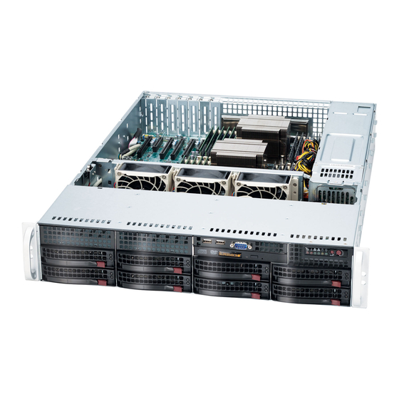
UPER ERVER 6027R-72RFT+ User's Manual Figure 6-1. Front and Rear Chassis Views 3.5" Drive Bays (2) DVD-ROM Drive (optional) USB Ports (2) COM Port Control Panel SAS/SATA Drives (8) System Reset Main Power 6 Low-profile PCI Slots Power Supplies Rear I/O Ports (see Figure 5-2) Control Panel The control panel (located on the front of the chassis) must be connected to the JF1 connector on the serverboard to provide you with system status indications. -
Page 63: System Fans
Installing a New Fan 1. Replace the failed fan with an identical 8-cm, 12 volt fan (available from Supermicro). 2. Position the new fan into the space vacated by the failed fan previously re- moved. A "click" can be heard when the fan is fully installed in place and the power connections are made. -
Page 64: Drive Bay Installation/Removal
SAS/SATA drives. Proceed to the next step for instructions. You must use standard 1" high, SAS/SATA drives in the system. Note: Refer to the following ftp site for setup guidelines: <ftp://ftp.supermicro.com/ driver/SAS/LSI/LSI_SAS_EmbMRAID_SWUG.pdf> and Supermicro's web site for additional inmformation <... -
Page 65: Sas/Sata Drive Installation
Chapter 6: Advanced Chassis Setup SAS/SATA Drive Installation These drives are mounted in carriers to simplify their installation and removal from the chassis. The carriers also help promote proper airflow for the drives. For this reason, even empty carriers without hard drives installed must remain in the chassis. Removing a Drive Carrier 1. -
Page 66: Hard Drive Backplane
UPER ERVER 6027R-72RFT+ User's Manual Figure 6-4. Mounting a Drive in a Carrier Use caution when working around the backplane. Do not touch the back- plane with any metal objects and make sure no ribbon cables touch the backplane or obstruct the holes, which aid in proper airflow. Important: Regardless of how many hard drives are installed, all drive carriers must remain in the drive bays to maintain proper airflow. -
Page 67: Power Supply
The PWR Fail LED will illuminate and remain on until the failed unit has been replaced. Replace- ment units can be ordered directly from Supermicro (see contact information in the Preface). The power supply units have a hot-swap capability, meaning you can replace the failed unit without powering down the system. - Page 68 UPER ERVER 6027R-72RFT+ User's Manual Notes...
-
Page 69: Chapter 7 Bios
Chapter 7: BIOS Chapter 7 BIOS Introduction This chapter describes the AMI BIOS Setup utility for the X9DR7-TF+. It also pro- vides the instructions on how to navigate the AMI BIOS Setup utility screens. The AMI ROM BIOS is stored in a Flash EEPROM and can be easily updated. Starting BIOS Setup Utility To enter the AMI BIOS Setup utility screens, press the <Del>... -
Page 70: How To Change The Configuration Data
<Delete> at the appropriate time during system boot. Note: For AMI UEFI BIOS Recovery, please refer to the UEFI BIOS Recovery User Guide posted @http://www.supermicro.com/support/manuals/. Starting the Setup Utility Normally, the only visible Power-On Self-Test (POST) routine is the memory test. - Page 71 Day MM/DD/YY format. The time is entered in HH:MM:SS format. (Note: The time is in the 24-hour format. For example, 5:30 P.M. appears as 17:30:00.). Supermicro X9DR7-TF+ Version This item displays the SMC version of the BIOS ROM used in this system.
-
Page 72: Advanced Setup Configurations
UPER ERVER 6027R-72RFT+ User's Manual Advanced Setup Configurations Select the Advanced tab to access the following submenu items. Boot Features Quiet Boot This feature allows the user to select bootup screen display between POST mes- sages and the OEM logo. Select Disabled to display the POST messages. Select Enabled to display the OEM logo instead of the normal POST messages. -
Page 73: Power Configuration
Chapter 7: BIOS Interrupt 19 Capture Interrupt 19 is the software interrupt that handles the boot disk function. When this item is set to Enabled, the ROM BIOS of the host adaptors will "capture" Interrupt 19 at bootup and allow the drives that are attached to these host adaptors to function as bootable disks. - Page 74 UPER ERVER 6027R-72RFT+ User's Manual • CPU Stepping • Maximum CPU Speed • Minimum CPU Speed • Processor Cores • Intel HT (Hyper-Threading) Technology • Intel VT-x Technology • Intel SMX Technology • L1 Data Cache • L1 Code Cache •...
- Page 75 Chapter 7: BIOS Active Processor Cores Set to Enabled to use a processor's second core and above. (Please refer to Intel's website for more information.) The options are All, 1, 2, 4 and 6. Limit CPUID Maximum This feature allows the user to set the maximum CPU ID value. Enable this function to boot the legacy operating systems that cannot support processors with extended CPUID functions.
-
Page 76: Cpu Power Management Configuration
UPER ERVER 6027R-72RFT+ User's Manual Intel® Virtualization Technology (Available when supported by the CPU) Select Enabled to support Intel Virtualization Technology, which will allow one platform to run multiple operating systems and applications in independent parti- tions, creating multiple "virtual" systems in one physical computer. The options are Enabled and Disabled. - Page 77 Chapter 7: BIOS CPU C6 Report (Available when Power Technology is set to Custom) Select Enabled to allow the BIOS to report the CPU C6 State (ACPI C3) to the operating system. During the CPU C6 State, the power to all cache is turned off.
-
Page 78: Chipset Configuration
UPER ERVER 6027R-72RFT+ User's Manual Short Duration Power Limit During Turbo Mode, the system may exceed the processors default power setting and exceed the Short Duration Power limit. By increasing this value, the proces- sor can provide better performance for short duration. This item displays the time period during which short duration power is maintained. -
Page 79: Qpi Configuration
Chapter 7: BIOS CPU1 Slot 1 PCI-E 3.0 x8 Link Speed This feature allows the user to set the PCI-Exp bus speed for the slot specified above. The options are Gen1 (Generation 1), Gen2 and Gen3. CPU1 Slot 2 PCI-E 3.0 x8 Link Speed This feature allows the user to set the PCI-Exp bus speed for the slot specified above. -
Page 80: Dimm Configuration
UPER ERVER 6027R-72RFT+ User's Manual QPI Link Frequency Select Use this feature to select the desired QPI frequency. The options are Auto, 6.4 GT/s, 7.2 GT/s, and 8.0 GT/s. DIMM Configuration This section displays the following DIMM information. Current Memory Mode This item displays the current memory mode. - Page 81 Chapter 7: BIOS Memory Energy/Performance Use this feature to determine the parameters for memory module energy con- sumption. Select Performance to maintian optimal functionality or select Energy Saving to reduce power consumption. The options are Performance and Energy Saving. DDR Speed Use this feature to force a DDR3 memory module to run at a frequency other than what is specified in the specification.
-
Page 82: South Bridge Configuration
UPER ERVER 6027R-72RFT+ User's Manual Thermal Throttling Throttling improves reliability and reduces power consumption in the proces- sor via automatic voltage control during processor idle states. The options are Disabled and CLTT (Closed Loop Thermal Throttling). South Bridge Configuration This feature allows the user to configure the settings for the Intel PCH chip. PCH Information This feature displays the following PCH information. -
Page 83: Sata Configuration
Chapter 7: BIOS SATA Configuration When this submenu is selected, the AMI BIOS automatically detects the presence of IDE or SATA devices and displays the following items. SATA Port0~SATA Port5: The AMI BIOS displays the status of each SATA port as detected by the BIOS. - Page 84 UPER ERVER 6027R-72RFT+ User's Manual RAID Mode The following items are displayed when RAID Mode is selected: Port 0~5 Hot Plug Select Enabled to enable hot-plug support for the particular port. The options are Enabled and Disabled. PCIe/PCI/PnP Configuration Launch Storage OpROM Priority In case of multiple Option ROMs (Legacy and UEFI-compatible), this feature speci- fies what ROM to launch.
-
Page 85: Super Io Configuration
Chapter 7: BIOS Warning: Enabling ASPM support may cause some PCI-E devices to fail! Above 4G Decoding (Available if the system supports 64-bit PCI decoding) Select Enabled to decode a PCI device that supports 64-bit in the space above 4G Address. -
Page 86: Serial Port 1 Configuration
UPER ERVER 6027R-72RFT+ User's Manual Serial Port 1 Configuration Serial Port Select Enabled to enable a serial port specified by the user. The options are En- abled and Disabled. Device Settings This item displays the settings of Serial Port 1. Change Settings This option specifies the base I/O port address and the Interrupt Request address of Serial Port 1 (COM). -
Page 87: Serial Port Console Redirection
Chapter 7: BIOS Device Mode Use this feature to select the desired mode for a serial port specified. The options are Normal and High Speed. Serial Port 2 Attribute Use this feature to select the attribute for this serial port. The options are SOL (Serial Over LAN), and COM. - Page 88 UPER ERVER 6027R-72RFT+ User's Manual Parity A parity bit can be sent along with regular data bits to detect data transmission errors. Select Even if the parity bit is set to 0, and the number of 1's in data bits is even.
- Page 89 Chapter 7: BIOS Serial Port for Out-of-Band Management/Windows Emergency Management Services (EMS) The submenu allows the user to configure Console Redirection settings to support Out-of-Band Serial Port management. Console Redirection (for EMS) Select Enabled to use a COM Port selected by the user for Console Redirection. The options are Enabled and Disabled.
-
Page 90: Acpi Settings
UPER ERVER 6027R-72RFT+ User's Manual ACPI Settings Use this feature to configure Advanced Configuration and Power Interface (ACPI) power management settings for your system. ACPI Sleep State Use this feature to select the ACPI State when the system is in sleep mode. Select S1 (CPU Stop Clock) to erase all CPU caches and stop executing instructions. - Page 91 Chapter 7: BIOS Pending Operation Use this item to schedule an operation for the security device. The options are None, Enable Take Ownership, Disable Take Ownership, and TPM Clear. Note: During restart, the computer will reboot in order to execute the pend- ing operation and change the state of the security device.
-
Page 92: Nic Configuration
UPER ERVER 6027R-72RFT+ User's Manual Intel TXT (LT-SX) Dependencies This feature displays the features that need to be enabled for the Intel Trusted Execution Technology to work properly in the system. VT-d Support: Intel Virtualization Technology with Direct I/O support VT Support: Intel Virtualization Technology support TPM Support: Trusted Platform support TPM State: Trusted Platform state... - Page 93 Chapter 7: BIOS Wake on LAN Wake on LAN is currently not supported for the 10 Gigabit LAN. Blink LEDs This feature allows the user to specify the duration for LEDs to blink. The range is from 0 ~ 15 seconds. The default setting is 0. PORT CONFIGURATION INFORMATION This section displays the following port information: •...
-
Page 94: Event Logs
UPER ERVER 6027R-72RFT+ User's Manual Event Logs Select the Event Logs tab to access the following submenu items. Change SMBIOS Event Log Settings This feature allows the user to configure SMBIOS Event settings. Enabling/Disabling Options SMBIOS Event Log Select Enabled to enable SMBIOS (System Management BIOS) Event Logging during system boot. - Page 95 Chapter 7: BIOS Erasing Settings Erase Event Log Select Enabled to erase the SMBIOS (System Management BIOS) Event Log, which is completed before a event logging is initialized upon system reboot. The options are No, Yes, Next reset, and Yes, Every reset. When Log is Full Select Erase Immediately to immediately erase SMBIOS error event logs that ex- ceed the limit when the SMBIOS event log is full.
-
Page 96: Ipmi
UPER ERVER 6027R-72RFT+ User's Manual IPMI Select the IPMI (Intelligent Platform Management Interface) tab to access the fol- lowing submenu items. IPMI Firmware Revision This item indicates the IPMI firmware revision used in your system. IPMI Status This item indicates the status of the IPMI firmware installed in your system. System Event Log ... -
Page 97: Bmc Network Configuration
Chapter 7: BIOS When SEL is Full This feature allows the user to decide what the BIOS should do when the system event log is full. Select Erase Immediately to erase all events in the log when the system event log is full. The options are Do Nothing and Erase Immediately. Custom EFI Logging Options Log EFI Status Codes Select Enabled to log EFI (Extensible Firmware Interface) Status Codes, Error... -
Page 98: Boot
UPER ERVER 6027R-72RFT+ User's Manual Gateway IP Address This item displays the Gateway IP address for this computer. This should be in decimal and in dotted quad form (i.e., 192.168.10.253). Boot This submenu allows the user to configure the following boot settings for the system. -
Page 99: Security
Chapter 7: BIOS Security This menu allows the user to configure the following security settings for the system. Password Check Use this feature to determine when a password entry is required. Select Setup to require the password only when entering setup. Select Always to require the pass- word when entering setup and on each boot. -
Page 100: Save & Exit
UPER ERVER 6027R-72RFT+ User's Manual Save & Exit This submenu allows the user to configure the Save and Exit settings for the system. Discard Changes and Exit Select this option to quit the BIOS Setup without making any permanent changes to the system configuration, and reboot the computer. - Page 101 Chapter 7: BIOS Discard Changes Select this feature and press <Enter> to discard all the changes and return to the BIOS setup. When the dialog box appears, asking you if you want to load previ- ous values, select Yes to load the values previous saved, or select No to keep the changes you've made so far.
- Page 102 UPER ERVER 6027R-72RFT+ User's Manual Notes 7-34...
-
Page 103: Appendix A Bios Error Beep Codes
Appendix A: BIOS Error Beep Codes Appendix A BIOS Error Beep Codes During the POST (Power-On Self-Test) routines, which are performed each time the system is powered on, errors may occur. Non-fatal errors are those which, in most cases, allow the system to continue the boot-up process. - Page 104 UPER ERVER 6027R-72RFT+ User's Manual Notes...
-
Page 105: Appendix B System Specifications
Appendix B: System Specifications Appendix B System Specifications Processors Single or dual Intel® Xeon E5-2600 Series processors Note: Please refer to our web site for a complete listing of supported processors. Chipset Intel C600 chipset BIOS 16 Mb AMI® SPI Flash ROM Memory Capacity Twenty-four DIMM sockets supporting up to 768 GB RDIMM, ECC LRDIMM or ECC/non-ECC UDIMM DDR3-1600/1333/1066/800 type memory... -
Page 106: System Cooling
UPER ERVER 6027R-72RFT+ User's Manual System Cooling Three 8-cm system cooling fans System Input Requirements AC Input Voltage: 100 - 240V AC auto-range Rated Input Current: 13 - 4A max Rated Input Frequency: 50 to 60 Hz Power Supply Rated Output Power: 740W (Part# PWS-741P-1R) Rated Output Voltages: +12V (61.7A), +5Vsb (4A) Operating Environment Operating Temperature: 10º... - Page 107 Appendix B: System Specifications Notes...
- Page 108 ERVER 6027R-72RFT+ User's Manual (continued from front) The products sold by Supermicro are not intended for and will not be used in life support systems, medical equipment, nuclear facilities or systems, aircraft, aircraft devices, aircraft/emergency com- munication devices or other critical systems whose failure to perform be reasonably expected to result in significant injury or loss of life or catastrophic property damage.
Need help?
Do you have a question about the SUPERSERVER 6027R-72RFT+ and is the answer not in the manual?
Questions and answers