
Related Manuals for Kramer 20-04400030


Summary of Contents for Kramer 20-04400030
- Page 1 USER MANUAL MODEL: VS-44UHDA 4x4 UHD Matrix Switcher P/N: 2900-300641 Rev 1 www.kramerAV.com...
-
Page 2: Table Of Contents
Managing Web Page Security Setting the Timeout Setting Switching Modes Setting Step-in Devices Managing the EDID Viewing the About Us Page Technical Specifications Default Communication Parameters Default Parameters Protocol 3000 Understanding Protocol 3000 Kramer Protocol 3000 Syntax Protocol 3000 Commands VS-44UHDA - Contents... -
Page 3: Introduction
Kramer Electronics Ltd. Introduction Welcome to Kramer Electronics! Since 1981, Kramer Electronics has been providing a world of unique, creative, and affordable solutions to the vast range of problems that confront the video, audio, presentation, and broadcasting professional on a daily basis. In recent years, we have... -
Page 4: Overview
European Advanced Recycling Network (EARN) and will cover any costs of treatment, recycling and recovery of waste Kramer Electronics branded equipment on arrival at the EARN facility. For details of Kramer’s recycling arrangements in your particular country go to our recycling pages at www.kramerav.com/support/recycling. -
Page 5: Typical Applications
Selectable switching speed. • Lock button to prevent tampering. • Kramer protocol 3000 support. • Firmware upgrade via mini USB, Ethernet or the RS-232 port. • Control Options – RS-232 serial commands transmitted by a PC, touch screen system or other serial controller, Ethernet port via LAN. -
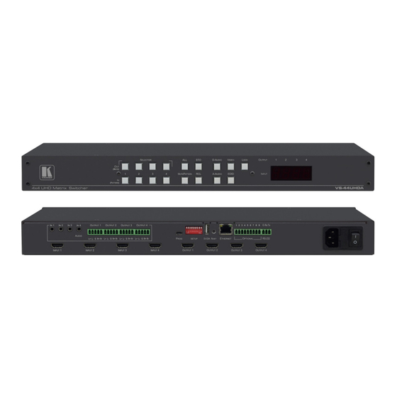
Page 6: Defining The Vs-44Uhda 4X4 Uhd Matrix Switcher
Kramer Electronics Ltd. Defining the VS-44UHDA 4x4 UHD Matrix Switcher This section defines the VS-44UHDA. Figure 1: VS-44UHDA 4x4 UHD Matrix Switcher Front Panel Feature Function The behavior of the front panel buttons and the 7-segment display changes along with the operation modes. - Page 7 Kramer Electronics Ltd. Figure 2: VS-44UHDA 4x4 UHD Matrix Switcher Rear Panel Feature Function AUDIO IN on 3.5 Mini Jack Connect to unbalanced stereo analog audio sources (from 1 to 4). Connectors INPUT HDMI Connector Connect to the HDMI source (from 1 to 4).
-
Page 8: Installing In A Rack
• If you are using a Kramer rack adapter kit (for a machine that is not 19"), see the Rack Adapters user manual for installation instructions available from our Web site www.kramerav.com/downloads/VS-44UHDA. -
Page 9: Connecting The Vs-44Uhda
Kramer Electronics Ltd. Connecting the VS-44UHDA Always switch off the power to each device before connecting it to your VS-44UHDA. After connecting your VS-44UHDA, connect its power and then switch on the power to each device. Although this connecting example shows only several inputs and outputs that are connected, you can connect all the inputs and outputs simultaneously. -
Page 10: Connecting Balanced/Unbalanced Stereo Audio Output
Kramer Electronics Ltd. Figure 3: Connecting to the VS-44UHDA Rear Panel Connecting Balanced/Unbalanced Stereo Audio Output The following are the pinouts for connecting to balanced or unbalanced stereo audio sources: Figure 5: Connecting an Unbalanced Stereo Figure 4: Connecting to a Balanced... -
Page 11: Connecting Vs-44Uhda Via The Ethernet Port
Kramer Electronics Ltd. Connecting VS-44UHDA via the ETHERNET Port You can connect to the VS-44UHDA via Ethernet using either of the following methods: • Directly to the PC using a crossover cable (see Connecting the Ethernet Port Directly to a on page 9). - Page 12 Kramer Electronics Ltd. 5. Click Properties. The Internet Protocol Properties window relevant to your IT system appears as shown in Figure 7 Figure Figure 7: Internet Protocol Version 4 Properties Window Figure 8: Internet Protocol Version 6 Properties Window 6. Select Use the following IP Address for static IP addressing and fill in the details as...
- Page 13 Kramer Electronics Ltd. Figure 9: Internet Protocol Properties Window 7. Click OK. 8. Click Close. Connecting the Ethernet Port via a Network Hub or Switch VS-44UHDA You can connect the Ethernet port of the to the Ethernet port on a network hub or using a straight-through cable with RJ-45 connectors.
-
Page 14: Operating Vs-44Uhda Via Front Panel Buttons
Kramer Electronics Ltd. Operating VS-44UHDA via Front Panel Buttons Press the power switch to power the device. During the 10-second initialization process, the: • 7-segment display LEDs are on. • All the front panel buttons illuminate. • The FPGA/EPLD version (P), the firmware version (F) and the build version (b) appear in succession. - Page 15 Kramer Electronics Ltd. Switching the Video Signal The VIDEO button on the VS-44UHDA front panel enables video routing. To switch a video input to an output: 1. Press VIDEO The button illuminates and the 7-segment display shows the current IN-OUT video status.
- Page 16 Kramer Electronics Ltd. Routing an Analog Audio Input to HDMI and Analog Audio Outputs The A-AUDIO button on the VS-44UHDA front panel enables to route the analog audio input signals to the balanced stereo analog audio outputs and the HDMI outputs...
- Page 17 Kramer Electronics Ltd. Routing a Digital Audio Input to HDMI and Analog Outputs The D-AUDIO VS-44UHDA button on the front panel enables to route the HDMI embedded audio input signals to the balanced stereo audio outputs and the HDMI outputs Generally, digital routing is enabled by pressing D-AUDIO: •...
- Page 18 Kramer Electronics Ltd. Switching the Video and the Audio Signal Simultaneously You can select the analog or the digital audio signal to switch to the output together with the video signal. To switch the digital audio and video signals together to an output: 1.
- Page 19 Kramer Electronics Ltd. Muting/Unmuting an Output You can mute/unmute an audio signal and a video signal separately. To mute/unmute an audio signal: 1. Press A-AUDIO or D-AUDIO. The buttons illuminate. 2. Press an OUT (MUTE) button (1 to 4). Press ALL (instead of an output button) to mute/unmute all the outputs.
- Page 20 Kramer Electronics Ltd. Routing a Pattern to the Output VS-44UHDA generates 8 embedded patterns. These patterns can be routed at a resolution of 480p to any of the outputs. Once a pattern is selected, that same pattern is routed to all the selected outputs.
- Page 21 Kramer Electronics Ltd. Operating in ARC Mode ARC (Audio Return Channel) can be set via the front panel buttons or the embedded webpages (see Switching Audio in Breakaway Mode on page Setting Input Parameters on page 32). VS-44UHDA features three types of audio return channels (ARC): •...
- Page 22 Kramer Electronics Ltd. To route an HDMI OUT ARC to a balanced stereo audio output port: 1. Press D-AUDIO and A-AUDIO simultaneously. Both buttons illuminate and the device enters the ARC routing mode (for example, HDMI OUT 1, 2, 3 and 4 are enabled).
- Page 23 Kramer Electronics Ltd. 2. Press one or more output buttons: • If the selected button flashes, that output to set to ARC mode. • If the selected button stops flashing, ARC mode is disabled for that output. The LOCK button flashes.
- Page 24 Kramer Electronics Ltd. Routing Analog Audio Inputs to HDMI Input Ports To route an analog audio input to an HDMI input, enable ARC on the HDMI input ports and then route them. To set an HDMI input to ARC mode: ARC can be enabled or disabled at any time, regardless of whether an amplifier is connected to the HDMI input or not.
-
Page 25: Storing And Recalling A Setup
Kramer Electronics Ltd. On the 7-segment display: • “.” under an output number indicates that arc is enabled on the corresponding output (outputs 1 to 4 in this example). • “A” under an output number indicates that an analog audio input is routed to that output. -
Page 26: Setting The Switching Mode
Kramer Electronics Ltd. To recall a setup: 1. Press RCL The RCL button illuminates. 2. Press an IN or OUT button to recall the setup stored in that IN/OUT. The selected button flashes. If a setup is stored in the selected setup button, the corresponding 7-segment display LED flashes. -
Page 27: Setting The Switching Speed
Kramer Electronics Ltd. Setting the Switching Speed Set the following switching speed modes separately for each output: Ex-Fast switch speed (IN 1). • • Fast switch speed (IN 2). • Normal switch speed (IN 3). To select the switching speed: 1. -
Page 28: Copying The Edid
Kramer Electronics Ltd. Copying the EDID You can copy the EDID to an input from a connected output or use the default EDID. To copy the EDID from a connected output: 1. Press and hold EDID and STO until both buttons illuminate. -
Page 29: Firmware Upgrade
The Ethernet, using embedded Web pages. • By USB or RS-232 using Kramer K-UPLOAD tool. The latest firmware version and the latest version of K-UPLOAD and installation instructions can be downloaded from the Kramer Web site at www.kramerav.com/downloads/VS-44UHDA VS-44UHDA - Firmware Upgrade... -
Page 30: Using The Embedded Web Pages
Kramer Electronics Ltd. Using the Embedded Web Pages The Web pages let you control the VS-44UHDA via the Ethernet. The Web pages include all the OSD items and more, and are accessed using a Web browser and an Ethernet connection. - Page 31 Kramer Electronics Ltd. To browse the VS-44UHDA Web pages: 1. Open your Internet browser. 2. Type the IP address of the device in the address bar of your browser. For example, the default IP address: The Authentication window appears (if set, security is enabled): Figure 12: Using the Embedded Web Pages –...
-
Page 32: Switching And Setting The Ports
Kramer Electronics Ltd. Switching and Setting the Ports The Switching Web page enables performing the following functions: • Viewing and Adjusting the Output Settings on page 30. • Viewing and Adjusting the Input Settings on page 32. • Switching an Input to an Output on page 34. - Page 33 Kramer Electronics Ltd. Figure 15: Switching Page – Editing the Output Button Settings 4. If required, type the label name in the Label text box and click Figure 16: Switching Page – Changing the Output Label 5. Click switch speed dropdown box to set the switching speed (normal, fast or extra-fast).
- Page 34 Kramer Electronics Ltd. Viewing and Adjusting the Input Settings VS-44UHDA Each of the input buttons lets you view and adjust the status of that input/output. Figure 17: Switching Page – Input Button Each input button displays the: • Input signal HDCP status – supports HDCP ( ) or does not support HDCP ( •...
- Page 35 Kramer Electronics Ltd. 7. In ARC mode click the settings button ( The input ARC Settings window appears: Figure 19: Switching Page – Input ARC Settings Window 8. Select an ARC source for input 1: either from analog inputs IN 1 to IN 4, or from HDMI outputs 1 to 4.
- Page 36 Kramer Electronics Ltd. Switching an Input to an Output To switch an input to an output: 1. In the Navigation pane, click Switching. The Switching page appears. 2. Click the AFV tab. Figure 20: Switching Page – AFV Tab 3. Click an output button or check the Outputs box. The button turns purple.
- Page 37 Kramer Electronics Ltd. Switching a Pattern to an Output To switch a pattern to an output: 1. In the Navigation pane, click Switching. The Switching page appears. 2. Click the AFV tab. Verify that Patterns (and not Inputs) is selected.
- Page 38 Kramer Electronics Ltd. Switching Audio in Breakaway Mode In breakaway mode, the HDMI embedded audio is switched separately from the video signal. The audio breakaway mode is enabled only when Auto Switch Setting is set to Manual mode. Set the volume and balance of each analog output using the appropriate sliders or mute/unmute the audio signal of an output: Figure 22: Switching Page –...
- Page 39 Kramer Electronics Ltd. input and can be switched to any analog output. Once an output is set to the ARC mode, the Inputs ARC button (on the right) is enabled and changes from gray to white. Figure 23: Switching Page – Output 1 Set to ARC Mode 4.
-
Page 40: Changing Device Settings And Upgrading The Firmware
Kramer Electronics Ltd. Changing Device Settings and Upgrading the Firmware The Device Settings Web page shows the device details, such as name, MAC address and firmware version and also enables performing the following functions: Changing the Ethernet Settings on page 38. -
Page 41: Managing Web Page Security
Kramer Electronics Ltd. Performing a Factory Reset To reset the device to its factory default values: 1. In the Navigation pane, click Device Settings. The Device Settings page appears (Figure 24). 2. Click Reset. The following window appears: Figure 25: Device Settings Page – Factory Reset 3. - Page 42 Kramer Electronics Ltd. 2. Set Activate Security to OFF. The following message appears: Figure 27: Password Settings Page – Deactivating the Security 3. Click OK. The Web page reloads. To access Web pages using the password: 1. Check the current security status.
- Page 43 Kramer Electronics Ltd. 4. Type the User Name (Admin, by default) and Password (left empty by default). Figure 31: Password Settings Page – Password Protection 5. Click Log In. 6. Select Password from the Navigation pane. Figure 32: Password Settings Page – Setting the Admin Password 7.
-
Page 44: Setting The Timeout
Kramer Electronics Ltd. 9. Click OK. The page is reloaded and can be accessed by entering the password. The top right side of the Web page displays the security icon: Figure 35: Password Settings Page – Admin Icon Setting the Timeout Use the Timeout Settings Web page to set the time delay to shut down if no input signal is detected for each output and also to set the auto switching time. -
Page 45: Setting Switching Modes
Kramer Electronics Ltd. ON – The audio signal routed to the output remains active when the video source • (coming from a different input) is deactivated. • OFF – The audio signal routed to the output is deactivated together with the deactivation of the video source (coming from a different input). -
Page 46: Setting Step-In Devices
Figure 39: Auto Switch Settings Page – Last Connected Mode Setting Step-in Devices Use the Step-In Settings page to manage Step-in devices (for example, Kramer DIP-31). If a step-in device is not connected to VS-44UHDA, the following page appears: VS-44UHDA - Using the Embedded Web Pages... - Page 47 Kramer Electronics Ltd. Figure 40: Step-In Settings Page (Step-in Device is not Connected) To manage a step-in device: 1. Connect the HDMI output of a step-in device (for example, DIP-31) to an HDMI input on the VS-44UHDA. 2. In the Navigation pane, click Step-In Settings. The Step-In Settings page appears and the input button/s to which the step-in device/s is connected appears purple.
-
Page 48: Managing The Edid
Kramer Electronics Ltd. 5. Press the STEP-IN button on DIP-31. The selected step-in button is routed to all the checked outputs. Any time the output Step-in configuration changes, press the STEP-IN button on the Step-In device to update the configuration. - Page 49 Kramer Electronics Ltd. Figure 42: EDID Management Page – Select an EDID Source VS-44UHDA - Using the Embedded Web Pages...
- Page 50 Kramer Electronics Ltd. 2. Select the EDID source: a connected output. When reading from an output, make sure that the output is connected to an acceptor. Figure 43: EDID Management Page – Select an EDID output 3. Select an input (or all the inputs) to which the EDID is copied.
- Page 51 Kramer Electronics Ltd. 4. Click COPY. The EDID message appears. Figure 45: EDID Page –EDID Copy Message 5. Click OK. The following message appears: Figure 46: EDID Management Page – Loading the EDID from Output to Input 6. Click OK.
- Page 52 Kramer Electronics Ltd. To read the EDID from an input to another input/s: 1. In the Navigation pane, click EDID Management. The EDID Management page appears. 2. Select an input from the list (on the left). 3. If required, check the options under Inputs Capabilities.
- Page 53 Kramer Electronics Ltd. To read the EDID from a file: 1. In the Navigation pane, click EDID Management. The EDID Management page appears. 2. Click File BROWSE and open the EDID file. Figure 48: EDID Management Page – EDID Selected from a File 3.
-
Page 54: Viewing The About Us Page
When viewing the 7-segment display in the EDID mode, the input with EDID read from a file will display “L” Viewing the About Us Page VS-44UHDA About Us page lets you view the Web page version and Kramer Electronics Ltd details. Figure 51: About Page VS-44UHDA - Using the Embedded Web Pages... -
Page 55: Technical Specifications
Kramer Electronics Ltd. Technical Specifications Inputs 4 HDMI On female HDMI connectors 4 Stereo Analog Unbalanced Audio On 3.5mm mini jacks Outputs 4 HDMI On female HDMI connectors 4 Stereo Balanced Audio On 5-pin terminal blocks (+4dBu nominal) Ports 1 USB... -
Page 56: Default Parameters
Auto Switching settings All video inputs are routed to each of the video outputs Default switching mode - manual/auto Manual, IN1 to OUT1,etcc for 2,3,4 Default EDID Kramer default EDID with "monitor name"= VS-44UHDA " " Lock EDID state Not locked... -
Page 57: Protocol 3000
PC to the serial or Ethernet port on the VS-44UHDA. To enter CR press the Enter key (LF is also sent but is ignored by the command parser). Commands sent from various non-Kramer controllers (e.g., Crestron) may require special coding for some characters (such as, /X##). For more information, refer to your controller’s documentation. -
Page 58: Understanding Protocol 3000
Kramer Electronics Ltd. For more information about Protocol 3000 commands, see: • Understanding Protocol 3000 on page • Kramer Protocol 3000 Syntax on page • Protocol 3000 Commands on page Understanding Protocol 3000 Protocol 3000 commands are structured according to the following: Command –... -
Page 59: Kramer Protocol 3000 Syntax
Kramer Electronics Ltd. Kramer Protocol 3000 Syntax The Kramer Protocol 3000 syntax uses the following delimiters: • CR = Carriage return (ASCII 13 = 0x0D) LF = Line feed (ASCII 10 = 0x0A) • • SP = Space (ASCII 32 = 0x20) Some commands have short name syntax in addition to long name syntax to enable faster typing. -
Page 60: Protocol 3000 Commands
Kramer Electronics Ltd. Protocol 3000 Commands This section includes the following commands: • Common Commands on page System Commands on page • • Authentication Commands on page • EDID Handling Commands on page • Switch Commands on page • Switching Commands on page •... - Page 61 Kramer Electronics Ltd. BUILD-DATE Functions Permission Transparency Set: BUILD-DATE? Get: End User Public Description Syntax Set: #BUILD-DATE?CR Get: Get device build date Response ~nn@BUILD-DATESPdateSPtimeCR LF Parameters date – Format: YYYY/MM/DD where YYYY = Year, MM = Month, DD = Day time –...
- Page 62 Kramer Electronics Ltd. MODEL Functions Permission Transparency Set: MODEL? Get: End User Public Description Syntax Set: Get: Get device model #MODEL?CR Response ~nn@MODELSPmodel_nameCR LF Parameters model_name – String of up to 19 printable ASCII chars Notes This command identifies equipment connected to Step-in master products and notifies of identity changes to the connected equipment.
- Page 63 Kramer Electronics Ltd. Functions Permission Transparency Set: Get: End User Public Description Syntax Set: #SN?CR Get: Get device serial number Response ~nn@SNSPserial_numberCR LF Parameters serial_number – 11 decimal digits, factory assigned Notes This device has a 14 digit serial number, only the last 11 digits are displayed.
- Page 64 Kramer Electronics Ltd. LOCK-FP Functions Permission Transparency LOCK-FP Set: End User Public LOCK-FP? End User Public Description Syntax #LOCK-FPSPlock_modeCR Set: Lock front panel #LOCK-FP? Get: Get front panel lock state Response ~nn@LOCK-FPSPlock_modeSPOKCR LF Parameters lock_mode – 0 (Off, unlock the front panel buttons), 1 (On, lock the front panel buttons)
- Page 65 Kramer Electronics Ltd. System Commands Command Description SIGNAL Get input signal lock status PRST-VID? Get video connections from saved preset PRST-STO Store current connections to preset PRST-RCL Recall saved preset list BAUD Set/get protocol serial port baud rate HDCP-STAT? Get HDCP signal status...
- Page 66 Kramer Electronics Ltd. PRST-VID? Functions Permission Transparency Set: PRST-VID? Get: End User Public Description Syntax Set: #PRST-VID?SPpreset,outCR Get: Get video connections from saved preset #PRST-VID?SPpreset,*CR Response ~nn@PRST-VIDSPpreset,in>outCR LF ~nn@PRST-VIDSPpreset,in>1,in>2,in>3,…CR LF Parameters preset – preset number in – input number or '0' if output disconnected >...
- Page 67 Kramer Electronics Ltd. PRST-RCL Functions Permission Transparency PRST-RCL Set: End User Public Description Syntax #PRST-RCLSPpresetCR Set: Recall saved preset list Get: Response ~nn@PRST-RCLSPpresetCR LF Parameters preset – preset number: 1(OUT 1)… 4(OUT 84); 5(IN 1)…8(IN 4) K-Config Example Recall preset 1: “#PRST-RCL 1”,0x0D...
- Page 68 Kramer Electronics Ltd. HDCP-STAT Functions Permission Transparency Set: HDCP-STAT? End User Public Description Syntax Set: None #HDCP-STAT?SPstage,stage_idCR Get: Get HDCP signal status Response ~nn@HDCP-STATSPstage,stage_id,statusCR LF Parameters stage – 0 (input), 1 (output) stage_id – for input stage: 1 (IN 1), 2 (IN 2), 3 (IN 3), 4 (IN 4), 0 (output disconnected), for output stage 1 (OUT 1), 2 (OUT 2), 3 (OUT 3), 4 (OUT 4), * (all outputs) status –...
- Page 69 Kramer Electronics Ltd. FPGA-VER Functions Permission Transparency Set: FPGA-VER? End User Public Description Syntax Set: #FPGA-VER?SPidCR Get: Get current FPGA version Response ~nn@FPGA-VERSPid,expected_ver,actual_verCR LF Parameters id – FPGA ID expected_ver – expected FPGA version for current firmware actual_ver – actual FPGA version...
- Page 70 Kramer Electronics Ltd. LOGOUT Functions Permission Transparency LOGOUT Set: Not Secure Public Get: Description Syntax #LOGOUTCR Set: Cancel current permission level Get: Response ~nn@LOGOUTSPOKCR LF Notes Logs out from User or Administrator permission levels. K-Config Example “#LOGOUT”,0x0D PASS Functions Permission...
- Page 71 Kramer Electronics Ltd. EDID Handling Commands Additional EDID data functions can be performed via a compatible EDID management application, such as Kramer EDID Designer (see www.kramerav.com/product/EDID%20Designer). Command Description CPEDID Copy EDID data from the output to the input EEPROM CPEDID...
- Page 72 Kramer Electronics Ltd. Switch Commands Command Description Switch audio and video Set video switch state VID-PATTERN Select output pattern Switch audio only DISPLAY? Read if output is valid INFO-IO? Get number of inputs/outputs in the unit INFO-PRST Get maximum number of video/audio presets in the unit...
- Page 73 Kramer Electronics Ltd. VID-PATTERN Functions Permission Transparency VID-PATTERN Set: End User Public VID-PATTERN? End User Public Description Syntax #VID-PATTERNSPout,pattern_idCR Set: Select output pattern #VID-PATTERN?SPoutCR Get: Get current pattern selected Response Set:~nn@VID-PATTERNSPout,pattern_idCR LF Get:~nn@VID-PATTERNSPout,pattern_idCR LF Parameters out – output number: 1 (OUT 1), 2 (OUT 2), 3 (OUT 3), 4 (OUT 4) >...
- Page 74 Kramer Electronics Ltd. DISPLAY Functions Permission Transparency Set: DISPLAY? End User Public Description Syntax Set: #DISPLAY?SPout_idCR Get: Get output HPD status Response ~nn@DISPLAYSPout_id,statusCR LF Parameters out_id – 1 (Output 1), 2 (Output 2) status – HPD status according to signal validation : 0 (Off), 1 (On), 2 (On and all parameters are stable...
- Page 75 Kramer Electronics Ltd. INFO-PRST Functions Permission Transparency Set: INFO-PRST? Get: End User Public Description Syntax Set: #INFO-PRST?CR Get: Get maximum preset count Response ~nn@INFO-PRSTSPVIDSPpreset_video_count,AUDSPpreset_audio_countCR LF Parameters preset_video_count – maximum number of video presets in the unit preset_audio_count – maximum number of audio presets in the unit...
- Page 76 Kramer Electronics Ltd. Switching Commands Command Description MTX-MODE Set/get to auto-switch mode VMUTE Set/get video on output status ROUTE Set/get layer routing MTX-MODE Functions Permission Transparency MTX-MODE Set: End User Public MTX-MODE? Get: End User Public Description Syntax #MTX-MODESPoutput_id,modeCR Set:...
- Page 77 Kramer Electronics Ltd. ROUTE Functions Permission Transparency ROUTE Set: End User Public ROUTE? Get: End User Public Description Syntax #ROUTESPlayer,dest,srcCR Set: Set layer routing #ROUTE?SPlayer,destCR Get: Get layer routing Response ROUTESPlayer,dest,srcCR LF Parameters layer – 1 (video), 2 (audio) dest – 1 (HDMI OUT 1), 2 (HDMI OUT 2), 3 (HDMI OUT 3), 4 (HDMI OUT 4), 5 (Analog OUT 1), 6 (Analog OUT 2), 7 (Analog OUT 3), 8 (Analog OUT 4), * (all outputs) src –...
- Page 78 ~nn@BALANCESPchannel,balance_levelCR LF Parameters channel – output number: 1 (OUT 1), 2 (OUT 2), 3 (OUT 3), 4 (OUT 4) balance level – audio parameter in Kramer units, minus sign precedes negative values ++ increase current value -- decrease current value...
- Page 79 Kramer Electronics Ltd. AUD-LVL Functions Permission Transparency AUD-LVL Set: End User Public AUD-LVL? Get: End User Public Description Syntax #AUD-LVLSPstage,channel,volumeCR Set: Set volume for specific amplifier output #AUD-LVL?SPstage,channelCR Get: Get volume for specific amplifier output Response ~nn@AUD-LVLSPstage,channel,volumeCR LF Parameters stage – 2 (audio output) channel –...
- Page 80 Kramer Electronics Ltd. Communication Commands Command Description ETH-PORT Set/get Ethernet port protocol NET-DHCP Set/get DHCP mode NET-GATE Set/get gateway IP NET-IP Set/get IP address NET-MAC Get MAC address NET-MASK Set/get subnet mask ETH-PORT Functions Permission Transparency ETH-PORT Set: Administrator Public...
- Page 81 Kramer Electronics Ltd. NET-GATE Functions Permission Transparency NET-GATE Set: Administrator Public NET-GATE? Get: End User Public Description Syntax #NET-GATESPip_addressCR Set: Set gateway IP #NET-GATE?CR Get: Get gateway IP Response ~nn@NET-GATESPip_addressCR LF Parameters ip_address – gateway IP address, in the following format: xxx.xxx.xxx.xxx Notes A network gateway connects the device via another network, possibly over the Internet.
- Page 82 Kramer Electronics Ltd. NET-MASK Functions Permission Transparency NET-MASK Set: Administrator Public NET-MASK? Get: End User Public Description Syntax #NET-MASKSPnet_maskCR Set: Set subnet mask #NET-MASK?CR Get: Get subnet mask Response ~nn@NET-MASKSPnet_maskCR LF Parameters net_mask – format: xxx.xxx.xxx.xxx Response Triggers The subnet mask limits the Ethernet connection within the local network...
- Page 83 What Kramer Electronics Will Do Kramer Electronics will, at its sole option, provide one of the following three remedies to whatever extent it shall deem necessary to satisfy a proper claim under this limited warranty: Elect to repair or facilitate the repair of any defective parts within a reasonable period of time, free of any charge for the necessary parts and labor to complete the repair and restore this product to its proper operating condition.
- Page 84 SAFETY WARNING Disconnect the unit from the power supply before opening and servicing For the latest information on our products and a list of Kramer distributors, visit our Web site where updates to this user manual may be found. We welcome your questions, comments, and feedback.
Need help?
Do you have a question about the 20-04400030 and is the answer not in the manual?
Questions and answers