Table of Contents
Advertisement
Quick Links
FOUNDATION SERIES - PIER
Co-linear Direct Vent Gas Fireplaces
Installation and Operating Manual
Natural Gas
FDN-4-PIER
FDN-5-PIER
FDN-6-PIER
FDN-7-PIER
WARNING: If the information in these instructions are not followed exactly, a fire or explosion may result
causing property damage, personal injury or loss of life.
— Do not store or use gasoline or other flammable vapors and liquids in the vicinity of this or any other
appliance.
WHAT TO DO IF YOU SMELL GAS
—
•
Do not try to light any appliance.
•
Do not touch any electrical switch; do not use any phone in your building.
•
Immediately call your gas supplier from a neighbor's phone. Follow the gas supplier's instructions.
•
If you cannot reach your gas supplier, call the fire department.
— Installation and service must be performed by a qualified installer, service agency or the gas supplier.
Please contact your Heat & Glo dealer with any questions or concerns.
Heat & Glo • FDN-4-PIER, FDN-5-PIER, FDN-6-PIER, FDN-7-PIER Installation Manual • 16400-9803 Rev. o • 4/21
Heat & Glo, a brand of Hearth & Home Technologies
7571 215
Street West, Lakeville, MN 55044
th
www.heatnglo.com
For the location of your nearest Heat & Glo dealer,
please visit www.heatnglo.com.
Installer:
Leave this manual with the appliance.
Consumer: Retain this manual for future reference.
1
Advertisement
Table of Contents

Related Manuals for Heat&Glo FOUNDATION FDN-4-PIER


Summary of Contents for Heat&Glo FOUNDATION FDN-4-PIER
- Page 1 FOUNDATION SERIES - PIER Co-linear Direct Vent Gas Fireplaces Installation and Operating Manual Natural Gas FDN-4-PIER FDN-5-PIER FDN-6-PIER FDN-7-PIER Installer: Leave this manual with the appliance. Consumer: Retain this manual for future reference. WARNING: If the information in these instructions are not followed exactly, a fire or explosion may result causing property damage, personal injury or loss of life. — Do not store or use gasoline or other flammable vapors and liquids in the vicinity of this or any other appliance.
-
Page 2: Table Of Contents
TABLE OF CONTENTS Safety Information Electrical 35-41 A. Safety Icon Designations A. Field Wiring (At Install) B. Important Safety Considerations B. Field Wiring - Service and Troubleshooting C. Requirements for the Commonwealth of C.1 Terminals 1 & 2 - LED Lights Massachusetts C.2 Terminals 3 &... -
Page 3: Safety Information
1 - SAFETY INFORMATION This fireplace complies with ANSI Z21.50-2016·CSA 2.22-2016 “VENTED DECORATIVE GAS APPLIANCES”. Installation must conform with local building codes or in the absence of local building codes, with the National Fuel Gas Code, ANSI Z223.1/NFPA 54 - Current Edition, or the Natural or Propane Installation Code, CSA B149.1 A. SAFETY ICON DESIGNATIONS Various safety icons appear throughout this installation manual. Please familiarize yourself with the icons making sure you understand the serious consequences that may occur if ignored or if the products are handled inappropriately. IMPORTANT NOTE HOT GLASS WARNING This indicates additional instructions that you should consider... -
Page 4: Requirements For The Commonwealth Of Massachusetts
Inspection Note: The following requirements reference various The state or local gas inspector of the side wall horizon- Massachusetts and national codes not contained in this tally vented gas fueled equipment shall not approve the document. installation unless, upon inspection, the inspector ob- serves carbon monoxide detectors and signage installed C. Requirements for the Commonwealth of in accordance with the provisions of 248 CMR 5.08(2)(a)1... -
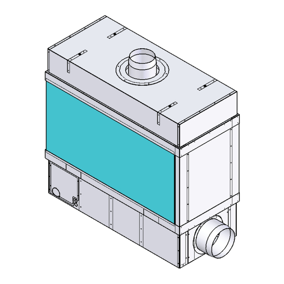
Page 5: Fireplace Specifications
2 - FIREPLACE SPECIFICATIONS A. PIER DIMENSIONS FLUE B-VENT [305] 2X 1/2 1 25/32 [13] 2X 1/2 [45] [13] [76] [76] [381] ACCESS PANEL 2X 5/8 6 1/8 ACCESS PANEL [156] [16] FRONT AND REAR [16] 6 21/32 INTAKE COLLAR [169] [305] SPECIFICATIONS DIMENSIONS B-VENT OUTSIDE... -
Page 6: Clearances
2 - FIREPLACE SPECIFICATIONS SPECIFICATIONS TABLE PROPANE MODEL # DESCRIPTION B-VENT REG PV IN-LINE PV BTU'S NG ORIFICE ORIFICE FDN-4-PIER 4X2 PIER 8” 10” PVK-45 PVI-45 60,000 (3X) #43 (3X) #55 FDN-5-PIER 5X2 PIER 8” 10” PVK-45 PVI-45 80,000 (4X) #43 (4X) #55 FDN-6-PIER 6X2 PIER 10”... - Page 7 B. CLEARANCES From unit left & right sides 1" 25mm To flooring under fireplace Unit top to ceiling 48" 122cm Unit side to adjacent sidewall 1" 25mm From appliance front* CLEARANCES SHOWN ARE MINIMUM TO COMBUSTIBLES Figure 2B NON-COMBUSTIBLE FRAMING AND FINISHING MATERIALS ALLOWED RIGHT UP TO THE FIREPLACE. 1/2”...
-
Page 8: Installation Overview
2 - FIREPLACE SPECIFICATIONS NOTE: The qualified installer should follow the procedure best suited for the installation. C. INSTALLATION OVERVIEW Framing should be built after the fireplace is installed or extra clearance must be planned for at the intake collar. Framing must allow for vent installation. If masonry (optional) will be used, prepare foundation for the masonry load. A lintel is required to support the added weight above the fireplace. Install hearth if desired. -
Page 9: Prepare The Fireplace
3 - PREPARE THE FIREPLACE CAUTION: FIREPLACE IS NOT LOAD-BEARING. NOTE: OTHER CLEARANCES APPLY. ALL CLEARANCES MUST BE MAINTAINED. A. STANDOFF INSTALLATION LOOSEN SCREW LOOSEN SCREW AND FOLD EACH AND FOLD EACH STANDOFF STANDOFF LOOSENED SCREW LOOSENED SCREW REMOVE REMOVE SECOND SCREW SECOND SCREW PIVOT FOLDED STANDOFF PIVOT FOLDED STANDOFF AND SECURE... - Page 10 Brace Removal Instructions NAILING FLANGES 1. Remove the shipping brace from the open end of the The Pier fireplace has a quantity of four (4) nailing appliance as highlighted in Figure 2. The brace is flanges that are secured with two (2) screws each on the retained with four sheet metal screws.
-
Page 11: Nailing Tab Installation
3 - PREPARE THE FIREPLACE B. NAILING TAB INSTALLATION Figure 3B.1 Figure 3B.2 Figure 3B.3 STEP 1: Refer to Figure 3B.1 STEP 2: Refer to Figure 3B.2 STEP 3: Refer to Figure 3B.3 & Figure 3B.4 The four (4) nailing flanges will be shipped in Bend the two (2) small tabs out on each Set each nailing flange in place and secure a flat state placed on the firebox back. nailing flange at the perforated lines. -
Page 12: Framing
4 - FRAMING NOTE: Framing dimensions should allow for wall covering thickness and fireplace facing materials. When using a hearth, adjust rough opening size as necessary to maintain at least minimum clearance requirements. CAUTION: Install fireplace on metal, concrete or hard wood surface extending the full width and depth of fireplace. CAUTION: Vent cap location must be in compliance with guidelines in Section 8 of this manual. CAUTION: FIREPLACE IS NOT LOAD-BEARING. If masonry is to be used (optional), prepare the necessary foundation for the masonry load. When masonry construction is being used, a lintel must be used over top of fireplace to support the added weight. Build hearth to desired size and height. If a hearth extension is desired, combustible material may be used. -
Page 13: Pier Framing Dimensions
4 - FRAMING A. PIER Framing Dimensions IMPORTANT: FIREPLACE IS NOT LOAD-BEARING. Refer to Section 5A for information on the 1/2" standoffs. Refer to Section 4B for information regarding supporting the fireplace hood with 1/4-20 threaded rods. MINIMUM NON-COMBUSTIBLE ZONE 6 IN. [152 mm] 1/2” Standoffs 1/2” Standoffs NOTE: Fireplace MUST be square in both directions prior to finishing or the glass will not fit properly. IMPORTANT FRAMING NOTES: PIER FRAMING SHOULD BE BUILT AFTER THE FIREPLACE IS INSTALLED OR EXTRA CLEARANCE MUST... -
Page 14: Fireplace Support
4 - FRAMING B. Fireplace Support Threaded Rods The hood must be supported using .250-.20 UNC threaded rods at the locations noted as "Required" in Figure 4B.1. Additional threaded rods can be installed in the locations noted as "Optional" in Figure 4B.1. The hood shall be supported at specific locations using .250-20 UNC threaded rods. - Page 15 4 - FRAMING Threaded Rod Installation There are several different ways to support the fireplace top and one option is to use a Unistrut installed over the fireplace that is secured to structurally sound framing. Refer to Figure 4B.3 or 4B.4. For each threaded rod installation you may need: Qty 1 Qty 1...
-
Page 16: Mantel Requirements
5 - MANTEL REQUIREMENTS A. NON-COMBUSTIBLE ZONE - USING THE PROVIDED 1/2" STANDOFFS The fireplace has standoffs installed on the front of the fireplace standard from the factory. They are located on the upper left, center and right front of the fireplace and are to ensure that the 1/2" [12.7mm] required clearance to combustibles on the surface of the fireplace is maintained. -
Page 17: Non-Combustible Zone - Not Using The Provided
5 - MANTEL REQUIREMENTS B. NON-COMBUSTIBLE ZONE - NOT USING THE PROVIDED 1/2" STANDOFFS The fireplace has standoffs installed on the front of the fireplace standard from the factory. They are located on the left, center and right front hood of the fireplace and are to ensure that the 1/2" [12.7mm] required clearance to combustibles on the surface of the fireplace is maintained. -
Page 18: Glass Frame Assembly
6 - GLASS FRAME ASSEMBLY A. GLASS FRAME ASSEMBLY IDENTIFICATION GLASS UPPER GROOVE LOWER FILLER STRIP SITS OVER GLASS CLIPS QUALITY SUCTION CUP LOWER GROOVE GLASS CLIP Figure 6B.1 Figure 6A CAUTION: TO PREVENT GLASS FRAME ASSEMBLY FROM FALLING FROM FIREPLACE AND BECOMING DAMAGED, FOLLOW THE INSTRUCTIONS EXACTLY WHEN REMOVING AND INSTALLING GLASS FRAME ASSEMBLY. STOP: DO NOT OPERATE THIS FIREPLACE WITH THE GLASS REMOVED, CRACKED OR BROKEN. REPLACEMENT OF GLASS ASSEMBLY SHOULD BE DONE BY A LICENSED OR QUALIFIED SERVICE PERSON. -
Page 19: Install Glass Frame Assembly
6 - GLASS FRAME ASSEMBLY Refer to Glass Frame Assembly Identification Figures 6A & 6B.1 when installing and removing the glass frame assembly. B. INSTALL GLASS FRAME ASSEMBLY IMPORTANT: PLASTIC EDGE PROTECTORS The fireplace is shipped with plastic edge protectors on the outer panes of glass only. If the edge protectors on the outer panes of glass are not U-Shaped installed, the glass may rattle during operation. -
Page 20: Gas Line Specifications & Access
7 - GAS LINE SPECIFICATIONS & ACCESS This fireplace is manufactured for use with Natural Gas or Propane. CAUTION: Installation of the gas line must only be done by a qualified person in accordance with local building codes, if any. If not, follow ANSI Z223.1. NOTE: The appliance and its individual shutoff valve must be disconnected from the gas supply piping system during any pressure testing of that system at pressures in excess of ½ psi. NOTE: The appliance must be isolated from the gas supply piping system by closing its individual manual shut-off valve during any pressure testing of the gas line at test pressures equal to or less than ½ psi (3.5 kPa). NOTE: For high altitude installations above 2000 feet, fireplace does not need to be derated. A. GAS LINE CONNECTION GAS LINE CONNECTION Propane Natural Gas 11.0 inches W.C. 7.0 inches W.C. MINIMUM INLET GAS PRESSURE (recommended) (recommended) MAXIMUM INLET GAS PRESSURE 14.0 inches W.C. 10.0 inches W.C. MANIFOLD PRESSURE (HI) 10.0 inches W.C. -
Page 21: Gas And Electrical Access Panels
7 - GAS LINE SPECIFICATIONS & ACCESS B. GAS AND ELECTRICAL ACCESS PANELS Each fireplace will have four points of access for installation and service. There are access panels on the pilot side of the fireplace front, side and rear of the fireplace. Plan in advance of the installation which access location will be used and accommodate for it in the finish work to allow for easy access to service later. -
Page 22: Venting
8 - VENTING CAUTION: Consult the local and national installation codes to assure adequate combustion and ventilation air is available. NOTE: Flame height and appearance will vary depending upon venting configuration and type of fuel used. Venting requirements apply to both Natural and Propane gas. STOP: MAINTAIN ALL CLEARANCES AS STATED IN THIS INSTALLATION MANUAL. A. APPROVED VENTING IN-LINE Model # B-VENT INTAKE AIR POWER VENT POWER VENT FDN-4-PIER 4X2 PIER 8" 10" PVK-45 PVI-45 FDN-5-PIER 5X2 PIER 8” 10” PVK-45 PVI-45 FDN-6-PIER 6X2 PIER 10”... - Page 23 Available Power Venting A power vent (PVK-45 or PVK-67) is approved for use with this appliance. It is crucial that all B-Vent pipe and elbow joints, and the longitudinal seam are sealed using a high temperature RTV Silicone and/or foil tape. NOTE: All pipe and elbow joints must be sealed. This includes the longitudinal seam on the pipe. High Temp RTV Silicone and/or foil tape MUST be used on each joint/seam.
- Page 24 Available In-Line Power Venting An in-line power vent (PVI-45 or PVI-67) is approved for use with this appliance. It is crucial that all B-Vent pipe and elbow joints, and the longitudinal seam are sealed using a high temperature RTV Silicone and/or foil tape. NOTE: All pipe and elbow joints must be sealed. This includes the longitudinal seam on the pipe.
- Page 25 IN-LINE POWERVENT PREPARATION - PVI-67 Perform the following steps when installing the PVI-67 on six foot and seven foot models. 1. Attach the provided 10 inch B-Vent collar to the intake side of the powervent. The intake side is located opposite the fan motor as shown in Figure 8A.6.
-
Page 26: Pitot Tube Information
B. PITOT TUBE INFORMATION There is a 1/4" pitot tube mounted in the center of the flue collar and is Figure 8B connected to the pressure switch (Figure 8B). This monitors the pressure in the flue and is necessary for proper operation. Take care to keep the end of the tube clean. -
Page 27: Vertical Terminations
8 - VENTING E. VERTICAL TERMINATIONS • The Foundation Series fireplace must terminate with the included approved powered termination cap. • NO SUBSTITUTION IS ACCEPTABLE. Carefully follow the instructions included with the approved powered termination cap. • • DO NOT use an additional speed control on this powervent. • You must use the included Capacitor. • All pipe seams must be sealed with aluminum tape or high temperature silicone (minimum 300 ºF). F. HORIZONTAL TERMINATION VENT CAP LOCATION & CLEARANCES This gas appliance must not be connected to a chimney serving any other appliance. • Terminations against vinyl siding must use a vinyl siding protector. Follow instructions included. • DO NOT RECESS TERMINATION KIT INTO OUTSIDE BUILDING MATERIALS - i.e.: brick, stone, siding, etc. If necessary, extend framing so that termination kit will be exposed once building materials are installed. - Page 28 8 - VENTING F. HORIZONTAL TERMINATION VENT CAP LOCATION & CLEARANCES Note: For horizontal terminations, it is advised that the hinges on the powervent be positioned to the left or right, rather than top or bottom, for safer maintenance. Inside Corner Outside Corner Recessed Location G = Combustible 24” (609.6mm) F = Combustible 6”...
-
Page 29: Powervent And Air-Intake Placement Clearances
8 - VENTING G. POWERVENT AND AIR-INTAKE PLACEMENT CLEARANCES RS SERIES POWERVENT IN-LINE POWERVENT (LOUVER 8/10) X = Intake X = Intake PV = Vent PV = Vent 0” P.V. 0” 0” 36” 24” 9” 9” 9” Minimum Clearance Using an RS Series Powervent Minimum Clearance Using an In-Line Powervent Intake Placed Above Vent = 36 Inches Intake Placed Below Vent = 24 Inches Intake Placed to Left Side, Right Side or Below Vent = 9 Inches... -
Page 30: Vertical Termination Vent Cap Location & Clearances
8 - VENTING H. VERTICAL TERMINATION VENT CAP LOCATION AND CLEARANCES ROOF PITCH H (Min.) Ft. H (Min.) M FLAT TO 6/12 1.0* 0.30 OVER 6/12 TO 7/12 1.25* 0.38 OVER 7/12 TO 8/12 1.5* 0.46 OVER 8/12 TO 9/12 2.0* 0.61 OVER 9/12 TO 10/12 2.5* 0.76 OVER 10/12 TO 11/12 3.25 0.99 OVER 11/12 TO 12/12 1.22 OVER 12/12 TO 14/12 1.52 OVER 14/12 TO 16/12 1.83 OVER 16/12 TO 18/12 2.13 * = 3 foot minimum in OVER 18/12 TO 20/12 2.27 snowy regions... -
Page 31: Roof Termination Cap Installation With And Without
8 - VENTING I. ROOF TERMINATION CAP INSTALLATION - WITH AND WITHOUT DAMPER Roof Termination With Optional Mechanical Damper POWERVENT MOUNTING BRACKETS OR DRILL MOUNTING HOLES TO MATCH BASE INSULATION PAD MUST BE CUT IN CENTER TO ACCOMMODATE VENT SIZE. MECHANICAL OPTIONAL FLUE DAMPER Note: Access to all mechanical components must be maintained for service and maintenance. -
Page 32: Wall Termination Cap Installation With And Without
8 - VENTING J. WALL TERMINATION CAP INSTALLATION - WITH AND WITHOUT DAMPER Wall Termination With Optional Mechanical Damper OPTIONAL MECHANICAL FLUE DAMPER DRILL 1/4” HOLES TO MATCH POWER VENT BASE INSULATION PAD MUST BE CUT IN CENTER TO ACCOMMODATE VENT SIZE. USE APPROPRIATE HEAVY DUTY FASTENERS TO SECURE POWER VENT ACCESS PANEL NEEDED FOR DAMPER MOTOR SERVICE... -
Page 33: Intake Air
K. INTAKE AIR This fireplace has the options of air intake connections on the side or the bottom of the fireplace. This fireplace is approved for use with 10 inch rigid metal pipe or UL approved 10 inch Class 0 or Class 1 flex for intake air. Use Table 8K.1 for venting requirements if using UL approved 10 inch flex for intake air. -
Page 34: Optional Universal Exhaust In Air-Intake Louver
8 - VENTING M. OPTIONAL UNIVERSAL EXHAUST IN AIR-INTAKE LOUVER MODEL UNITS LOUVER-8 4 ft, 5 ft Exhaust and Air-Intake LOUVER-10 6 ft., 7 ft Exhaust and Air-Intake This kit is an optional method of terminating the fresh air and/or exhaust for the appliance. Exhaust terminations must be installed with an inline powervent. -
Page 35: Electrical
9 - ELECTRICAL A. FIELD WIRING (AT INSTALL) See Terminal Details in Section 9B and 9C. Figure 9A Cap shown is from the PVK Series VAC AMP HP PVK-45 JUNCTION BOX WITH CAPACITOR PVK-67 PVI-45 TO FAN PVI-67 5.3 13/16 GREEN Insulation Pad BLACK BLACK BLACK (Must be cut in center to accomodate vent size.) BLACK WHITE Optional Mechanical Damper... -
Page 36: Field Wiring - Service And Troubleshooting
9 - ELECTRICAL B. FIELD WIRING (SERVICE & TROUBLESHOOTING) Figure 9B Note: The entire electrical system (including powervent) must be grounded for proper operation. Heat & Glo • FDN-4-PIER, FDN-5-PIER, FDN-6-PIER, FDN-7-PIER Installation Manual • 16400-9803 Rev. o • 4/21... -
Page 37: Terminals 1 & 2 - Led Lights
9 - ELECTRICAL C.1 TERMINALS 1 & 2 - LED Lights Figure 9C.1 Terminals 1 & 2 C.2 TERMINALS 3 & 4 - Main Flame Figure 9C.2 Terminals 3 & 4 Heat & Glo • FDN-4-PIER, FDN-5-PIER, FDN-6-PIER, FDN-7-PIER Installation Manual • 16400-9803 Rev. o • 4/21... -
Page 38: Terminals 5 & 6 - Fireplace Power
9 - ELECTRICAL C.3 TERMINALS 5 & 6 - Fireplace Power Figure 9C.3 Terminals 5 & 6 C.4 TERMINALS 7 & 8 - Powervent Connection 120VAC POWERVENT / IN-LINE POWERVENT NEUTRAL POWERVENT / IN-LINE POWERVENT Figure 9C.4 Terminals 7 & 8 Heat & Glo • FDN-4-PIER, FDN-5-PIER, FDN-6-PIER, FDN-7-PIER Installation Manual • 16400-9803 Rev. o • 4/21... -
Page 39: Terminals 9 & 10 - Flue Damper Connection
9 - ELECTRICAL C.5 TERMINALS 9 & 10 - Flue Damper Connection NOTE: OPTIONAL IF A DAMPER IS NOT USED DO NOT CONNECT ANYTHING TO TERMINALS 9 & 10 Figure 9C.5 Terminals 9 & 10 Heat & Glo • FDN-4-PIER, FDN-5-PIER, FDN-6-PIER, FDN-7-PIER Installation Manual • 16400-9803 Rev. o • 4/21... -
Page 40: Terminals 11 & 12 - Flue Damper Prove
9 - ELECTRICAL C.6 TERMINALS 11 & 12 - Flue Damper Prove (24 VAC) SEE NOTE NOTE: OPTIONAL IF A DAMPER IS NOT USED TERMINALS 11 AND 12 HAVE A JUMPER ACROSS THEM Figure 9C.6 Terminals 11 & 12 Heat & Glo • FDN-4-PIER, FDN-5-PIER, FDN-6-PIER, FDN-7-PIER Installation Manual • 16400-9803 Rev. o • 4/21... -
Page 41: Finishing The Wall
10 - FINISHING A. FINISHING THE WALL - USING THE PROVIDED 1/2" STANDOFFS NOTE: REFER TO DIMENSIONS SECTION FOR ALLOWABLE FINISHING DIMENSIONS REQUIRED TO FIT THE GLASS PANELS INTO THE FIREPLACE. FINISHING MATERIALS MUST NOT OVERLAP THE FRAMING DIMENSIONS HIGHLIGHTED IN SECTION 2.A. NEVER COVER THE GLASS WITH FINISHING MATERIALS. NOTE: DO NOT PIERCE ANY OF THE BLACK PAINTED SURFACES WITH SCREWS, RIVETS, ETC. THIS INCLUDES THE 3" BLACK TOP AND BOTTOM GLASS TRIM AND ANY PAINTED SIDES ADJACENT TO THE GLASS. NOTE: REFER TO MANTEL REQUIREMENTS: NON-COMBUSTIBLE ZONE USING PROVIDED 1/2" STANDOFFS FOR MORE INFORMATION (SECTION 5A). WARNING! Risk of Fire! DO NOT apply combustible materials beyond the minimum clearances. Figure 10A.1 Comply with all minimum clearances to combustibles as specified in this manual. -
Page 42: Finishing The Wall -Not Using The Provided 1/2" Standoffs
10 - FINISHING B. FINISHING THE WALL - NOT USING THE PROVIDED 1/2" STANDOFFS NOTE: REFER TO DIMENSIONS SECTION FOR ALLOWABLE FINISHING DIMENSIONS REQUIRED TO FIT THE GLASS PANELS INTO THE FIREPLACE. FINISHING MATERIALS MUST NOT OVERLAP THE FRAMING DIMENSIONS HIGHLIGHTED IN SECTION 2.A. NEVER COVER THE GLASS WITH FINISHING MATERIALS. NOTE: DO NOT PIERCE ANY OF THE BLACK PAINTED SURFACES WITH SCREWS, RIVETS, ETC. THIS INCLUDES THE 3" BLACK TOP AND BOTTOM GLASS TRIM AND ANY PAINTED SIDES ADJACENT TO THE GLASS. NOTE: REFER TO MANTEL REQUIREMENTS: NON-COMBUSTIBLE ZONE NOT USING PROVIDED 1/2" STANDOFFS FOR MORE INFORMATION (SECTION 5B). -
Page 43: Lighting & Shutdown
11 - LIGHTING & SHUTDOWN FOR YOUR SAFETY - READ BEFORE LIGHTING STOP: IF YOU DO NOT FOLLOW THESE INSTRUCTIONS EXACTLY, A FIRE OR EXPLOSION MAY RESULT, CAUSING PROPERTY DAMAGE, PERSONAL INJURY OR LOSS OF LIFE. UE TO HIGH SURFACE TEMPERATURES, KEEP CHILDREN, CLOTHING AND FURNITURE AWAY. This appliance needs fresh air for safe operation and must be installed so there are provisions for adequate combustion and ventilation air. It is important to make sure the termination cap remains unobstructed at all times from snow, ice, leaves or other debris. •... -
Page 44: If The Fireplace Does Not Light
11 - LIGHTING & SHUTDOWN STOP! Read safety information on previous page and front cover of this manual before continuing. NOTE: This fireplace is equipped with an ignition device which automatically lights the pilot. DO NOT try to light the pilot by hand. B. IF THE FIREPLACE DOES NOT LIGHT Turn off the fireplace at switch. Turn off all electrical power to fireplace. Wait five (5) minutes to allow any gas that may have accumulated inside firebox to escape. If you then smell gas, STOP! Follow safety information on front cover and on previous page of the installation manual. -
Page 45: Pressure Testing
12 - PRESSURE TESTING NOTE: The appliance and its individual shutoff valve must be disconnected from the gas supply piping system during any pressure testing of that system at pressures in excess of ½ psi. NOTE: The appliance must be isolated from the gas supply piping system by closing its individual manual shut-off valve during any pressure testing of the gas line at test pressures equal to or less than ½ psi (3.5 kPa). INLET PRESSURE TEST The valve has an allen plug on the inlet and outlet. Install a barb fitting on the tap you want to measure. Light the fireplace, check the pressure. Turn off fireplace; reinstall plug. Check for leaks. -
Page 46: Maintenance
14 - MAINTENANCE The appliance is required to be inspected at least once a year by a professional service person. The compartment below firebox (behind lower access panel) must be cleaned at least once a year, more frequent cleaning may be required due to excessive lint from carpeting, bedding materials, or other fibrous materials. It is imperative that the burner be cleaned once a year. VALVE AND ELECTRICAL ACCESS There is an access panel in the floor of the firebox should more extensive service be needed. Using the suction cups (provided with the appliance) remove the inner and outer glass panels. Remove the glass media or natural stones on the end with the pilot. Remove the screws on the mesh screen and remove the mesh screen. Remove the Phillips head screws on the LED “U” shaped metal tray and gently fold metal tray over the burners. Remove the 6 screws on the solid access panel and remove panel. NOTE: INSTALLATION AND REPAIR SHOULD BE DONE ONLY BY QUALIFIED SERVICE PERSON. THE APPLIANCE SHOULD BE INSPECTED BEFORE USE AND ANNUALLY BY A QUALIFIED SERVICE PERSON. MORE FREQUENT CLEANING MAY BE REQUIRED DUE TO EXCESSIVE LINT FROM CARPETING, BEDDING MATERIALS, ETC. IT IS IMPERATIVE THAT CONTROL COMPARTMENTS, BURNERS AND CIRCULATION AIR PASSAGEWAYS OF THE APPLIANCE BE KEPT CLEAN. -
Page 47: Replacement Parts List
C. REPLACEMENT PARTS LIST PART PART NUMBER PART PART NUMBER Gas Valve SV9501 End Service Glass GLA-P-IN (INNER) (All Sizes - Inner) Pilot (Natural Gas / Propane) 112-5000-NG / 112-5000-LP End Service Glass Pilot Tube 16400-2851 GLA-P-OUT (OUTER) (All Sizes - Outer) Vacuum Switch 112-5003 Transformer, 24 VAC 112-5002 NOTE: All appliances utilize two pieces of side ser- Orifice, NG #43 16400-2043 vice glass. The Outer pane of glass has the plastic Orifice, Propane #55 16400-2055 U-Channel on the top and bottom. - Page 48 C. REPLACEMENT PARTS LIST PART PART NUMBER PART PART 8 Inch Exhaust Collar 16400-1450 8 Inch / 10 Inch Chimney Collar 8 Inch Exhaust Collar 10 Inch Intake/Exhaust Collar 16400-1550 8 IN. DIA. Transformer, 12 VDC 16400-1900 6 IN. LED Controller 16400-1901 LED Remote Control 16400-1901R Switch, 15 Amp Toggle 16400-3013 117-001 = 8 IN. DIAMETER 16400-1450 2-Gang Electrical Box 16400-3014 117-002 = 10 IN. DIAMETER 10 Inch Intake/Exhaust Collar White Nylon 2-Gang Plate 16400-3015...
-
Page 49: Hht Limited Lifetime Warranty
Limited Lifetime Warranty Hearth & Home Technologies LLC LIMITED LIFETIME WARRANTY Hearth & Home Technologies LLC (“HHT”) extends the following warranty for HHT gas, wood, pellet and electric hearth appliances (each a “Product” and collectively, the “Product(s)”) and certain component parts set forth in the table below (“Component Part(s)”) that are purchased from a HHT authorized dealer or distributor. - Page 50 Limited Lifetime Warranty (continued) WARRANTY CONDITIONS: • Because HHT cannot control the quality of any Products sold by unauthorized sellers, this Warranty only covers Products that are purchased through an HHT authorized dealer or distributor unless otherwise prohibited by law; a list of HHT authorized dealers is available on the HHT branded websites.
Need help?
Do you have a question about the FOUNDATION FDN-4-PIER and is the answer not in the manual?
Questions and answers