Table of Contents
Advertisement
Quick Links
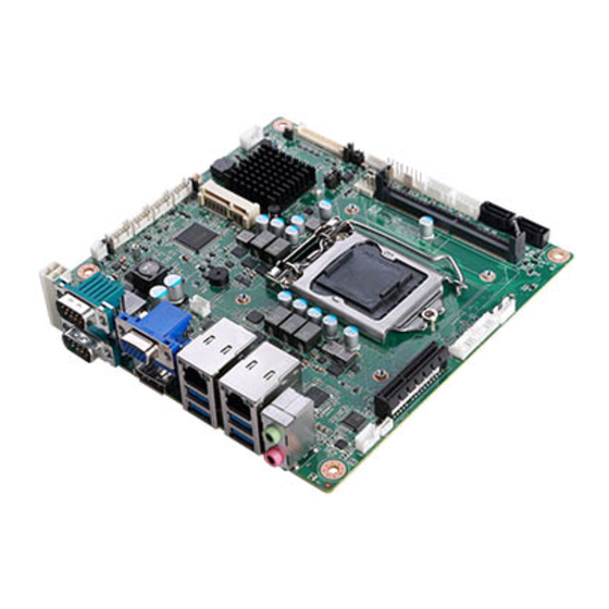
PPC-MB-8260AE Mini-ITX Motherboard with Intel®
Core™ i7/i5/i3/Pentium®/Celeron® LGA 1151 CPU, DP/
VGA, 5 COM, 6 USB, Dual LAN, PCIe x4, and Mini PCIe
Startup Manual
Packing List
Before card installation, please ensure that the following
items have been included in your shipment:
1. 1 x PPC-MB-8260AE mini-ITX motherboard
2. 4 x COM cables (2 x 5-pin cables)
3. 1 x SATA cable
4. 1 x PPC-MB-8260AE startup manual
5. 1 x Warranty card
6. 1 x Thermal grease
7. 14 x COM port screws
8. 1 x Mini PCIe packet screws
If any of these items are missing or damaged, contact your
distributor or sales representative immediately.
Note 1:
For detailed PPC-MB-8260AE specifications,
refer to the latest product information provided
on the Advantech website (PPC-61X1C model).
Note 2:
Acrobat Reader is required to view PDF files.The
Acrobat Reader software can be downloaded
from www.adobe.com/Products/acrobat/read-
step2.html (Acrobat is a trademark of Adobe).
For more information about this or other Advantech
products, visit our website at
http://www.advantech.com
For technical support and service, visit our support
website at
http://support.advantech.com
This manual is for PPC-MB-8260AE, Rev. A1.
Part No. 2003826002
Printed in China
Edition 3
December 2018
Specifications
Selected
PPC-MB-8260AE
M/B
KBL
i7-7700
CPU
SKL
i7-6700TE
Core #
Quad Core
3.6 GHz
KBL
(up to 4.2
GHz)
CPU
Max.
Speed
2.4 GHz
SKL
(up to 3.4
GHz)
KBL
L3
8M
Cache
SKL
KBL
65W
TDP
SKL
35W
Chipset
Intel® H110
1 x 260-pin SODIMM DDR4, 2133 MHz (up to
Memory
16 GB)
Network
2 x 10/100/1000 Mbps Ethernet, 2 x Intel® I211
(LAN)
1 x RS232/422/485,1 x RS232
1 x DP
I/O Port
1 x VGA
4 x USB 3.0
1 x Line-Out,1 x Mic-In
3 x RS232
1 x GPIO (8 channels)
1 x Speaker connector
Internal
1 x LED connector
Connector
2 x USB 2.0
1 x LVDS connector
1 x Touch connector
2 x SATA connector
Watchdog
255 timer intervals, configurable using software
Timer
Expansion
1 x Full-size mSATA or mini PCIe, 1 x PCIe x4 slot
Dimensions 170 x 170 mm (6.69 x 6.69")
Operating
Microsoft® Windows 7 (32/64 bit),
System
Windows 8.1 (64 bit), Windows 10 (64 bit*)
*Kaby lake processers only support Windows10 (64 bit)
PPC-MB-8260AE Startup Manual 1
i3-
i5-7500
/
/
7101E
Pen-
Cel-
i3-
tium
eron
i5-6500TE
6100TE
G4400
G3900
TE
TE
Dual
Dual
Dual
Quad Core
Core
Core
Core
3.4 GHz
3.9
(up to 3.8
/
/
GHz
GHz
2.3 GHz
2.7
2.4
2.3
(up to 3.3
GHz
GHz
GHz
GHz)
4M
/
/
6M
3M
3M
2M
65W
54W
/
/
35W
35W
35W
35W
Advertisement
Table of Contents

Related Manuals for Advantech PPC-MB-8260


Summary of Contents for Advantech PPC-MB-8260
- Page 1 3 x RS232 1 x GPIO (8 channels) 1 x Speaker connector Internal 1 x LED connector For more information about this or other Advantech Connector 2 x USB 2.0 products, visit our website at 1 x LVDS connector 1 x Touch connector http://www.advantech.com...
-
Page 2: Jumpers And Connectors
Jumpers and Connectors Jumpers and Connectors (Cont.) The PPC-MB-8260AE motherboard features a number of ATX_5Vsb1: ATX 5VSB Power Supply Connector jumpers that allow users to configure the system according to specific applications. The functions of each jumper and Definition connector are listed in the table below. +V5SB Connectors and Headers Connectors and Headers List... -
Page 3: Jumper Settings
Jumpers and Connectors (Cont.) Jumpers and Connectors (Cont.) GPIO5 CN4: Power LED Connector Definition GPIO1 +V5_DUAL GPIO6 GPIO2 GPIO7 GPIO3 AMP1: Audio Amplifier Output Connector Definition CN16: Touch Connector SPK L- Definition SPK L+ SPK R+ SPK R- SENSE Jumper Settings Jumpers List Sysfan 1 ~ 2: System Fan Power Connector Jumper... - Page 4 Jumpers and Connectors (Cont.) Jumpers and Connectors (Cont.) RTC Select (Jcmos1) LVDS PWM Power Select (JP5) (1-2) P3 Normal (default) (1-2) P11 (2-3) P4 Clear CMOS (2-3) P12 +V3.3 (default) Touch Power Select (JP2) COM Ring Select (JP6) (1-2) P5 +V3.3_DUAL (default) (1-3)/(2-4) COM 2/1 ring (default)
-
Page 5: Board Layout: Jumper And Connector Locations
Board Layout: Jumper and Connector Locations Installation Guide 1. Insert the memory module into the memory slot at a 45 2. Once inserted, gently press the memory module into degree angle, as shown below. Ensure that the gold the slot until the tabs snap into place, securing the fingers of the module are fully inserted into the slot. -
Page 6: Bios Setup Program
BIOS Setup Program BIOS Setup Program (Cont.) 1.1 Entering the BIOS Setup Utility 3. Select the “RS485” option. Autoflow and termination resistors can be enabled or disabled. When the power is turned on, press the <Del> button to enter the BIOS setup screen. After a setting is configured, press <F4>... -
Page 7: Graphics Configuration
BIOS Setup Program (Cont.) BIOS Setup Program (Cont.) 1.6 Graphics Configuration 2. Select the “Enabled” option for the “Network Stack” item. 1. Access the “System Agent (SA) Configuration” item from the “Chipset” tab. 1.5 Boot Option Filter 2. Click on the “Graphics Configuration” item. 1. - Page 8 BIOS Setup Program (Cont.) BIOS Setup Program (Cont.) 1.7 Wake-On-LAN and Ring 4. The Primary IGFX Boot Display item can be configured as “VBIOS Default”, “DP”, “LVDS”, or “CRT”. 1. In the “Chipset” tab click the “PCH-IO Configuration” item to access “PCIE Wake” configuration. Select the “Enabled”...
Need help?
Do you have a question about the PPC-MB-8260 and is the answer not in the manual?
Questions and answers