Advertisement
PPC-MB-620 Mini-ITX Motherboard with Intel® Core™ i9/
i7/i5/i3/Celeron® Processor, DP/HDMI, 5 x COM, 6 x USB,
3 x LAN, PCIe x16, and M.2 (M Key, B key and E Key)
Startup Manual
Packing List
Before installation, check to ensure that the following items
are included in the shipment:
1. 1 x PPC-MB-620 mini-ITX motherboard
2. 1 x COM cable (1-to-4 DB9)
3. 1 x SATA cable
4. 1 x PPC-MB-620 startup manual
5. 1 x Warranty card
6. 1 x Thermal grease
7. 14 x COM port screws
8. 2 x M.2 packet screws
If any of these items are missing or damaged, contact your
distributor or sales representative immediately.
Note 1: For detailed PPC-MB-620 specifications, refer
to the latest product information provided on the
Advantech website (PPC-600 model).
Note 2: Acrobat Reader is required to view PDF files.
This software can be downloaded from www.
adobe.com/Products/acrobat/readstep2.html
(Acrobat is a trademark of Adobe).
For more information about this or other Advantech
products, visit our website at
http://www.advantech.com
For technical support and service, visit our support
website at
http://support.advantech.com
This manual is for PPC-MB-620, Rev. A1.
Part No. 2044062000
Printed in China
Installation Guide
1. Insert the memory module into the memory slot at a 45
2. Once inserted, gently press the memory module into
Edition 1
March 2023
degree angle, as shown below. Ensure that the gold
fingers of the module are fully inserted into the slot.
the slot until the tabs snap into place, securing the
module in position.
PPC-MB-620 Startup Manual 1
45°
Advertisement
Table of Contents

Related Manuals for Advantech PPC-MB-620


Summary of Contents for Advantech PPC-MB-620
- Page 1 PPC-MB-620 Mini-ITX Motherboard with Intel® Core™ i9/ i7/i5/i3/Celeron® Processor, DP/HDMI, 5 x COM, 6 x USB, 3 x LAN, PCIe x16, and M.2 (M Key, B key and E Key) Startup Manual Packing List Installation Guide Before installation, check to ensure that the following items 1.
-
Page 2: Specifications
1 x slot (3042 & 3052 B key) supports PCIE & USB2.0 USB3.1 & USB2.0 PCIe x16 1 x slot (Gen5) Watchdog Timer 255 timer intervals, configurable using software Dimensions (W x H) 170 mm x 170 mm (6.69" x 6.69") OS support Microsoft® Win 10 IOT LTSC(64-bit)/Win 11, Linux 2 PPC-MB-620 Startup Manual... -
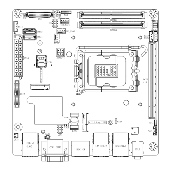
Page 3: Board Layout: Jumper And Connector Locations
Board Layout: Jumper and Connector Locations PPC-MB-620 Startup Manual 3... -
Page 4: Jumpers And Connectors
Jumpers and Connectors Jumpers and Connectors (Cont.) The PPC-MB-620 motherboard features a number of COM12: COM 2 Connector jumpers that allow users to configure the system according to specific applications. The functions of each jumper and Definition Definition Definition connector are listed in the table below. (RS-232) (RS-422) (RS-485) Connector and Headers TX RX- Connectors and Headers List... -
Page 5: Jumper Settings
CPUFAN1: CPU Fan Power Connector Definition POWER SPEED RTC Select (Jcmos1) (1-2) P3 Normal (default) (2-3) P4 Clear CMOS CN4: Power LED Connector Definition +V5_DUAL AMP1: Audio Amplifier Output Connector Definition SPK L- SPK L+ SPK R+ SPK R- PPC-MB-620 Startup Manual 5... - Page 6 (1-2) P5 Connect resistive touchscreen (default) (7-9)/(8-10) NC P6 Disconnect resistive touchscreen COM 2/1 12V P17/P18 LCD Power Select (JP3) (1-2) P7 (2-3) P8 +V3.3 (default) Enable Power Select (JP4) (1-2) P9 (2-3) P10 +V3.3 (default) 6 PPC-MB-620 Startup Manual...
Need help?
Do you have a question about the PPC-MB-620 and is the answer not in the manual?
Questions and answers