
Related Manuals for Advantech PCA-6781


Summary of Contents for Advantech PCA-6781
- Page 1 User Manual PCA-6781 ISA Celeron® M Half-sized SBC with VGA/LCD/LVDS/10/100 Ethernet/USB 2.0 and SSD...
- Page 2 No part of this manual may be reproduced, copied, translated or transmitted in any form or by any means without the prior written permission of Advantech Co., Ltd. Information provided in this manual is intended to be accurate and reliable. How- ever, Advantech Co., Ltd.
-
Page 3: Packing List
If any of these items are missing or damaged, contact your distributor or sales repre- sentative immediately. Additional Information and Assistance Visit the Advantech website at www.advantech.com where you can find the lat- est information about the product. Contact your distributor, sales representative, or Advantech's customer service center for technical support if you need additional assistance. -
Page 4: Declaration Of Conformity
Caution! There is a danger of a new battery exploding if it is incorrectly installed. Do not attempt to recharge, force open, or heat the battery. Replace the battery only with the same or equivalent type recommended by the man- ufacturer. Discard used batteries according to the manufacturer’s instructions. PCA-6781 User Manual... - Page 5 Intel Celeron M 600MHz (512KB L2) Intel 82551QM PCA-6781VE-S0A1E Intel Celeron M 1.0GHz (0 L2) Intel 82551QM PCA-6781LV-M0A1E Intel Celeron M 600MHz (512KB L2) PCA-6781 Memory Compatibility Table Advante Model Size Speed Type ECC Vendor PN Memory ch PN 128MB DDR266 DDR SODIMM N 77.10920.110...
- Page 6 PCA-6781 User Manual...
-
Page 7: Table Of Contents
2.12.2 LVDS LCD panel Connector (CN8) ..........16 2.12.3 LCD Inverter Connector (CN6) ........... 16 2.13 USB Connectors (CN9,CN11)..............16 2.14 Ethernet configuration ................16 2.14.1 LAN Connector (CN13)............... 16 2.14.2 Network boot................16 2.15 HDD LED/Reset/Power Button (CN1)............. 17 PCA-6781 User Manual... - Page 8 HDD LED/Reset/Power Button (CN1) ........46 Table B.1: HDD LED/Reset/Power Button (CN1) ...... 46 B.1.2 Primary IDE Connector (CN4) ............ 46 Table B.2: Primary IDE Connector (CN4)........46 B.1.3 Floppy Connector(CN2).............. 47 Table B.3: Floppy Connector (CN2) .......... 47 PCA-6781 User Manual viii...
- Page 9 System I/O Ports ..................54 Table C.1: System I/O Ports ............54 1st MB Memory Map ................55 Table C.2: 1st MB Memory Map ..........55 DMA Channel Assignments ..............55 Table C.3: DMA Channel Assignments........55 PCA-6781 User Manual...
- Page 10 Interrupt Assignments ................56 Table C.4: Interrupt Assignments ..........56 PCA-6781 User Manual...
-
Page 11: Chapter 1 General Information
Chapter General Information This chapter gives background information on the PCA-6781. Sections include: ! Introduction ! Features ! Specifications ! Board layout and Dimensions... -
Page 12: Introduction
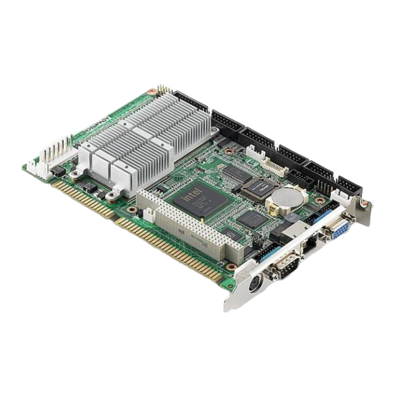
Introduction The PCA-6781 series is a half-sized ISA bus CPU card designed with powerful Intel Celeron M processor, with Intel 852GM and ICH4 chipset, which supports Dynamic Video Memory Technology. For maximum performance, PCA-6781 also supports one 200 Pin SODIMM socket and DDR memory up to 1 GB. These chipsets provide an optimized on-board integrated graphics solution. -
Page 13: Specifications
Display modes: – CRT Modes: 1600 X 1200 at 85 Hz; – LCD Modes: up to UXGA panel resolution with frequency range from 25 MHz to 112 MHz 1.3.3 Solid State disk Supports CompactFlash Card Type I/II PCA-6781 User Manual... -
Page 14: Ethernet Interface
Operating humidity: 0% ~ 90% Relative Humidity, non-condensing Note! If your power supply doesn’t have +12 V output (+5 V only), PCA-6781 needs to go T-part number to add the components for the 5 V to 12 V converting circuit, but LVDS and PC104 also cannot be used within +5 V only. -
Page 15: Board Layout: Dimensions
Board layout: dimensions Figure 1.1 Board Layout: Dimensions (Component Side) PCA-6781 User Manual... -
Page 16: Figure 1.2 Board Layout: Dimensions (Solder Side)
Figure 1.2 Board Layout: Dimensions (Solder Side) PCA-6781 User Manual... -
Page 17: Chapter 2 Installation
Chapter Installation This chapter explains the setup procedures of PCA-6781 hard- ware, including instructions on setting jumpers and connecting peripherals, switches and indica- tors. Be sure to read all safety pre- cautions before you begin the installation procedure. -
Page 18: Jumpers
Jumpers The PCA-6781 has a number of jumpers that allow you to configure your system to suit your application. The table below lists the functions of the various jumpers. Table 2.1: Jumpers Label Function LVDS Voltage choose AT/ATX Power choose jumper... -
Page 19: Locating Connectors (Component Side)
Locating Connectors (component side) CN27 CN26 CN6 CN8 CN7 CN10 CN11 CN13 CN14 CN15 CN25 CN16 CN18 CN19 CN22 CN17 CN12 CN21 CN23 Figure 2.1 Jumper & Connector Locations Locating Connectors (solder side) CN24 DIMM1 Figure 2.2 Connectors (Component Side) PCA-6781 User Manual... -
Page 20: Setting Jumpers
A pair of needle-nose pliers may be helpful when working with jumpers. If you have any doubts about the best hardware configuration for your application, contact your local distributor or sales representative before you make any changes. Generally, you simply need a standard cable to make most connections. PCA-6781 User Manual... -
Page 21: Front Panel (Cn1)
Suspend LED Reset 9-10 Power Button 2.5.2 LVDS Panel Power Select (J1) Table 2.4: LVDS Panel Power Select Function 1-2 (default) +3.3 V +5 V 2.5.3 LVDS VBR Select (J2) Table 2.5: LVDS VBR Select Function High PCA-6781 User Manual... -
Page 22: At/Atx Power Choose Jumper(J3)
2. Short pins 2 and 3 for a few seconds. 3. Return jumper to pins 1 and 2. 3. Turn on the system. The BIOS is now reset to its default setting. Table 2.7: Clear CMOS Function 1-2 (default) Normal Clear CMOS PCA-6781 User Manual... -
Page 23: Com2 Rs-232/422/485 Select (J5)
Gently push the SODIMM into a perpendicular position until the clips on the ends of the SODIMM sockets snap into place. Check to ensure that the SODIMM is correctly seated and all connector contacts touch. The SODIMM should not move around in its socket. PCA-6781 User Manual... -
Page 24: Main Power Connector (Cn16)
Main Power Connector (CN16) Supplies main power (+5 V and +12 V) to PCA-6781, and it is a 7 pins power connec- tor. Important! Make sure that the ATX power supply can take at least a 10 mA load on the 5 V standby lead (5 VSB). -
Page 25: Connecting The Floppy Drive
2.11 IDE Connector (CN4) The PCA-6781 provides one IDE channels to which you can attach up to two Enhanced Integrated Device Electronics hard disk drives or CDROM to the PCA- 6781’s internal controller. The PCA-6781's IDE controller uses a PCI interface. This advanced IDE controller supports faster data transfer, PIO Mode 3 or Mode 4, UDMA 33/66/100 mode. -
Page 26: Vga/Lvds Interface Connections
2.12.2 LVDS LCD panel Connector (CN8) PCA-6781 uses the Intel 852GM to supports single or dual-channel LVDS panels up to UXGA panel resolution with frequency range from 25MHz to 112MHz. The display mode can be 2 channels (2 x 18 bits) LVDS LCD panel displays Users can connect to either an 18, 24 or 36 bits LVDS LCD with CN8. -
Page 27: Hdd Led/Reset/Power Button (Cn1)
2.15 HDD LED/Reset/Power Button (CN1) Next, you may want to install external switches to monitor and control the PCA-6781. These features are optional: install them only if you need them. CN1 is an 2 x 5 pin header, 180 degree, male. It provides connections for reset and power & hard disk indicator. -
Page 28: External Keyboard Connector (Cn18)
2.18 External Keyboard Connector (CN18) In addition to the Mini keyboard connector on the PCA-6781’s rear plate, there is an additional onboard external keyboard connector, allowing for greater flexibility in sys- tem design. 2.19 Audio Interface Connector (CN7) The Audio Interface link is a 10 pin connector, the PCA-6781 can support Audio with the addition of optional PCM-231A-00A1. -
Page 29: Atx Suspend Power Connector(Cn23)
2.27 Hardware Fail LED (CN27) The PCA-6781 is equipped with 2-pin hardware fail pin header to connector with LED. If you connect CN27 with LED, LED will light when buzzer on PCA-6781 has a warning noise. PCA-6781 User Manual... - Page 30 PCA-6781 User Manual...
-
Page 31: Bios Operation
Chapter BIOS Operation This chapter describes how to set BIOS configuration data. Sections include: ! BIOS Introduction ! BIOS Setup... -
Page 32: Bios Introduction
CPUs from 386 through Pentium and AMD Geode, K7 and K8 (including multiple processor platforms), and VIA Eden C3 and C7 CPU. You can use Advantech’s utilities to select and install features to suit your designs as needed. BIOS Setup The PCA-6781 system has built-in Award BIOS with a CMOS SETUP utility which allows user to configure required settings or to activate certain system features. -
Page 33: Main Menu
Set Password Establish, change or disable password. Save & Exit Setup Save CMOS value settings to CMOS and exit BIOS setup. Exit Without Saving Abandon all CMOS value changes and exit BIOS setup. PCA-6781 User Manual... -
Page 34: Standard Cmos Features
5.25 inch AT-type high-density drive; 1.2 M byte capacity 720K, 3.5" 3.5 inch double-sided drive; 720 K byte capacity 1.44M, 3.5" 3.5 inch double-sided drive; 1.4 4M byte capacity 2.88M, 3.5" 3.5 inch double-sided drive; 2.88 M byte capacity. PCA-6781 User Manual... - Page 35 Extended Memory The POST of the BIOS will determine the amount of extended memory (above 1MB in CPU’s memory address map) installed in the system. Total Memory This item displays the total system memory size. PCA-6781 User Manual...
-
Page 36: Advanced Bios Features
3.2.3 Advanced BIOS Features Blank Boot [Disabled] (* Advantech feature enhancement) This item allows system only displays blank screen during BIOS Post stage. POST Beep [Enabled] (* Advantech feature enhancement) This item allows system send out Beep sound during BIOS Post stage. - Page 37 Show full screen logo during post stage, and the Logo picture can be customi- zation. Small Logo (EPA) Show [Enabled] Show EPA logo during system post stage. Summary Screen Show [Enabled] Show system status in Summary screen page. PCA-6781 User Manual...
-
Page 38: Advanced Chipset Features
This item enables users to set the operation speed of internal Graphic Chip FSB and DRAM, system default is setting to “Auto Max 266 MHz” to reference value. System BIOS Cacheable [Enabled] This item allows the system BIOS to be cached to allow faster execution and better performance. PCA-6781 User Manual... - Page 39 This Item enables users to set Initial display device of system boot up, system default is setting to “VBIOS Default” to reference value. Panel Number [640 X 480] This item enables users to set the Resolution of Panel Type, system default is setting to “640 X 480” to reference value. PCA-6781 User Manual...
-
Page 40: Integrated Peripherals
This item enables users to set the Onboard device status, includes enable USB, AC97, MC97 and LAN devices. Super IO Device This item enables users to set the Super IO device status, includes enable Floppy, COM, LPT, IR and control GPIO and Power fail status. PCA-6781 User Manual... -
Page 41: Power Management Setup
Initial display power management signaling. Video Off In Suspend [Yes] This item allows user to turn off Video during system enter suspend mode. Suspend Type [Stop Grant] This item allows user to determine the suspend type. Modem use IRQ[3] PCA-6781 User Manual... - Page 42 This item allows user to enable and key in Date/time to power on system. Disabled Disable this function. Enabled Enable alarm function to power on system. Data (of month) Alarm1-31 Time (HH:MM:SS) Alarm(0-23) : (0-59) : 0-59) PCA-6781 User Manual...
-
Page 43: Pnp/Pci Configurations
The item is designed to solve problems caused by some non-standard VGA cards. A built-in VGA system does not need this function. INT Pin 1~8 Assignment [Auto] The interrupt request (IRQ) line assigned to a device connected to the PCI inter- face on your system. PCA-6781 User Manual... -
Page 44: Pc Health Status
Current System/CPU Temp [Show Only] This item displays current system and CPU temperature. 3.3 V / 1.05 V / 2.5 V / 5 V / 12 V [Show Only] This item displays current CPU and system Voltage. PCA-6781 User Manual... -
Page 45: Frequency/Voltage Control
Spread Spectrum [Disabled] This item enables users to set the spread spectrum modulation. CPU Host/SRC/PCI Clock [Default] This item enables users to set the CPU Host and PCI clock by system auto- matic detection or by manual. PCA-6781 User Manual... -
Page 46: Load Optimized Defaults
Load Optimized Defaults loads the default system values directly from ROM. If the stored record created by the Setup program should ever become corrupted (and therefore unusable). These defaults will load automatically when you turn the PCA-6781 system on. 3.2.11 Set Password... - Page 47 Select Set Password again, and at the “Enter Password” prompt, please don’t enter anything; just press <Enter>. At the “Confirm Password” prompt, again, don’t type in anything; just press <Enter>. Select Save to CMOS and EXIT, type <Y>, then <Enter>. PCA-6781 User Manual...
-
Page 48: Save & Exit Setup
Typing "Y" will quit the BIOS Setup Utility and save user setup value to CMOS. Typing "N" will return to BIOS Setup Utility. 3.2.13 Quit Without Saving Note! Typing "Y" will quit the BIOS Setup Utility without saving to CMOS. Typing "N" will return to BIOS Setup Utility. PCA-6781 User Manual... -
Page 49: Driver Installation
Chapter Driver Installation This chapter gives you the driver installation information on the PCA-6781 Half-size CPU card. Sections include: ! Driver Introduction ! Driver Installation... -
Page 50: Driver Introduction
Driver Introduction The CD shipped with PCA-6781 should contain the drivers below; please follow this sequence to complete the driver installation. Install Intel INF Update Driver for Windows XP/2000. Install Intel Graphic Driver for Windows XP/2000. Install Intel 82551QM Ethernet Driver for Windows XP/2000. -
Page 51: Appendix A Watchdog Timer
Appendix Watchdog Timer The board is equipped with a watchdog timer that resets the CPU or generates an interrupt if processing comes to a standstill for any reason. This feature ensures system reliability in industrial standalone or unmanned environments. -
Page 52: Watchdog Programming
;65H ;bit [1:0]=Reserved ;bit [6:2]Reserve=00000 ;bit [7] WDT time-out Value Units Select ;Minutes=0 (default) Seconds=1 ;==================================================== mov dx,SCH3114_IO + 65h ; mov al,080h out dx,al ;==================================================== ;66H ;WDT timer time-out value ;bit[7:0]=0~255 ;==================================================== mov dx,SCH3114_IO + 66h PCA-6781 User Manual... - Page 53 ;==================================================== ;bit[0] status bit R/W ;WD timeout occurred =1 ;WD timer counting = 0 ;==================================================== mov dx,SCH3114_IO + 68h mov al,01h out dx,al .exit PCA-6781 User Manual...
- Page 54 PCA-6781 User Manual...
-
Page 55: Appendix B Pin Assignments
Appendix Pin Assignments This appendix contains informa- tion of a detailed or specialized nature. -
Page 56: Connectors
Table B.1: HDD LED/Reset/Power Button (CN1) Signal Signal +5 V HDD_LED PWR_LED SUSPEND +V3.3SB RESET 5 VSB PWR_Button B.1.2 Primary IDE Connector (CN4) Table B.2: Primary IDE Connector (CN4) Signal Signal IDE Reset IORDY Cable Select DACK IRQ14 DIAG# CS#1 CS#3 Active PCA-6781 User Manual... -
Page 57: Floppy Connector(Cn2)
Table B.3: Floppy Connector (CN2) Signal Signal RWC# INDEX# MOA# DSA# DIR# STEP# TRAK0# RDATA# HEAD# DSKCHG# B.1.4 Printer Port Connector (CN3) Table B.4: Printer Port Connector (CN3) Signal Signal STB# AFD# ERR# INIT# SLIN ACK# BUSY SLCT PCA-6781 User Manual... -
Page 58: Ir Connector (Cn5)
Data out ACRST +5 V SPKR B.1.8 LVDS Connector (CN8) Table B.8: LVDS Connector (CN8) Signal Signal LVDS0_D0+ LVDS1_D0+ LVDS0_D0- LVDS1_D0- VDS0_D1+ LVDS1_D1+ LVDS0_D1- LVDS1_D1- LVDS0_D2+ LVDS1_D2+ LVDS0_D2- LVDS1_D2- LVDS0_CLK+ LVDS1_CLK+ LVDS0_CLK- LVDS1_CLK- LVDS power LVDS power PCA-6781 User Manual... -
Page 59: Usb Port 1, 2 Connector (Cn9)
USB port 3,4 Connector (CN11) Table B.11: USB port 3,4 Connector (CN11) Signal Signal +5 V +5 V USB2- USB3- USB2+ USB3+ B.1.12PC 104 Connector B.1.13LAN RJ45 Connector (CN13) Table B.12: LAN RJ45 Connector (CN13) Signal Signal LILED VCC_LAN ACTLED VCC_LAN PCA-6781 User Manual... -
Page 60: Com Port 1 (Rs-232)(Cn15)
Signal TXD485+ TXD485- RXD485+ RXD485 B.1.16ATX Power Connector (CN16) Table B.15: ATX Power Connector (CN16) Signal Signal +5 V +12 V +5 V B.1.17KB/MS Connector (CN19) Table B.16: KB/MS Connector (CN19) Signal Signal KBDATA MSDATA KBCLK MSCLK PCA-6781 User Manual... -
Page 61: External Kb/Mouse Connector (Cn18)
Default value is set CN23 to short pin1-2. B.1.21Negative Power Input (CN17) Table B.19: Negative Power Input (CN17) Signal Signal -5 V -12 V B.1.22CF Connector (CN24) B.1.23+12V FAN connector(CN22) Table B.20: +12 V FAN connector (CN22) Signal Signal FAN_PWM +12 V FAN-SPD PCA-6781 User Manual... -
Page 62: System Fan Connector (Cn25)
Table B.24: LVDS Voltage Choose (JP1) Signal Signal +3.3V B.2.2 Clear CMOS (J1) Table B.25: CLEAR CMOS (J1) Signal Signal Normal Clear CMOS B.2.3 232/422/485 SEL (J2) Table B.26: 232/422/485 SEL (J2) Signal Signal RS232 * RS422 RS485 PCA-6781 User Manual... -
Page 63: Appendix C System Assignments
Appendix System Assignments This appendix contains informa- tion of a detailed nature. Sections include: ! System I/O ports ! 1st MB memory map ! DMA channel assignments ! Interrupt assignments... -
Page 64: System I/O Ports
PCI Configuration Data D00-FFFF -available for system use- 200-20F Game Port 2F8-2FF COM2 378-37F Printer Port (Standard & AFF) 3F0-3F1 Configuration Index/Data 3F0-3F7 Floppy Controller 3F8-3FF COM1 778-77A Printer Port (ECP Extensions) (Port 378+400) 800h~87fh Super I/O runtime reg PCA-6781 User Manual... -
Page 65: 1St Mb Memory Map
Function Available Available (audio) Floppy disk (8-bit transfer) Available (printer port) Cascade for DMA controller 1 Available Available Available * Audio DMA select 1, 3, or 5 ** Printer port DMA select 1 (LPT2) or 3 (LPT1) PCA-6781 User Manual... - Page 66 IRQ 12 PS/2 mouse IRQ 13 INT from co-processor IRQ 14 Primary IDE IRQ 15 Secondary IDE for CFC * Ethernet interface IRQ select: 5, 9, 10, 11 * PNP USB IRQ select: 5, 9, 10, 11 PCA-6781 User Manual...
- Page 67 PCA-6781 User Manual...
- Page 68 No part of this publication may be reproduced in any form or by any means, electronic, photocopying, recording or otherwise, without prior written permis- sion of the publisher. All brand and product names are trademarks or registered trademarks of their respective companies. © Advantech Co., Ltd. 2009...
Need help?
Do you have a question about the PCA-6781 and is the answer not in the manual?
Questions and answers