
Related Manuals for Advantech PCA-6029


Summary of Contents for Advantech PCA-6029
- Page 1 User Manual PCA-6029 Intel® Core™i7/i5/i3/Pentium® PICMG 1.0 Single Host Board with VGA/ DVI-D/ DDR4 /SATA3.0 / USB3.0 / Dual GbE...
- Page 2 No part of this manual may be reproduced, copied, translated, or transmitted in any form or by any means without the prior written permission of Advantech Co., Ltd. The information provided in this manual is intended to be accurate and reliable.
- Page 3 Whether your new Advantech equipment is destined for the labo- ratory or the factory floor, you can be assured that your product will provide the reliability and ease of operation for which the name Advantech has come to be known.
- Page 4 It should be free of marks and scratches and in perfect working order upon receipt. As you unpack the PCA-6029, check it for signs of ship- ping damage. (For example, damaged box, scratches, dents, etc.) If it is damaged or it fails to meet the specifications, notify our service department or your local sales representative immediately.
- Page 5 PCA-6029 User Manual...
- Page 6 PCA-6029 User Manual...
-
Page 7: Table Of Contents
Table 1.2: Connectors ..............5 Board Layout: Jumper and Connector Locations........6 Figure 1.1 Jumper and connector locations......... 6 Block Diagram................... 7 Figure 1.2 PCA-6029 Block Diagram........... 7 Safety Precautions ..................8 Jumper Settings ..................8 1.8.1 How to set jumpers ............... 8 1.8.2... - Page 8 Figure 3.38GateA20 setup screen..........52 Figure 3.39Option ROM Message setup screen ......52 Figure 3.40INT19 Trap Response setup screen ......53 Figure 3.41Boot option filter setup screen........53 Figure 3.42Network setup screen..........54 Figure 3.43Storage setup screen ..........54 PCA-6029 User Manual viii...
- Page 9 Figure 3.92Restore User Defaults setup screen......82 Figure 3.93UEFI setup screen............ 82 Figure 3.94Launch EFI Shell from file system setup screen ..83 Chapter Value-Added Software Services..85 Value-Added Software Services ............. 86 4.1.1 Software API ................86 4.1.2 Software Utility ................86 PCA-6029 User Manual...
- Page 10 External Keyboard Connector (KBMS2) ..........109 Table B.7: External keyboard connector (KBMS2) ....109 CPU Fan Power Connector (CPUFAN1) ..........109 Table B.8: CPU fan power connector (CPUFAN1) ....109 Power LED and Keyboard Lock Connector (JFP3 / PWR_LED & KEY PCA-6029 User Manual...
- Page 11 Table B.21:1 MB memory map ..........115 B.22 PCI Bus Map ..................115 Table B.22:PCI Bus Map ............115 Appendix C Programming the GPIO....117 Supported GPIO Register ..............118 GPIO Registers ..................118 GPIO Example Program-1 ..............118 PCA-6029 User Manual...
- Page 12 PCA-6029 User Manual...
-
Page 13: Chapter 1 Hardware Configuration
Chapter Hardware Configuration... -
Page 14: Introduction
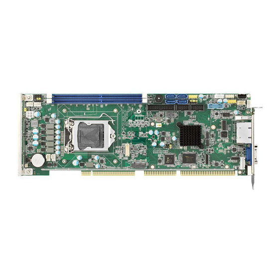
Introduction PCA-6029 is a PICMG 1.0 form-factor single host board which is designed with Intel® H110 PCH for industrial applications that need high computing power and strong I/O capability.PCA-6029 supports 22nm manufacturing technology, LGA1151 socket Intel® Core™ i7/i5/i3 and Pentium® processors that integrate memory and graphic controllers and support DDR4 2133/2400 MHz SDRAM up to 32 GB. -
Page 15: Specifications
PCA-6029 does NOT support PATA (IDE) interface. 1.3.2 Memory RAM: – PCA-6029: Up to 32 GB in two 240-pin DIMM sockets. Supports dual-chan- nel DDR4 2133/2400 MHz SDRAM WITHOUT ECC function. 1.3.3 Input/Output ISA bus: HISA (ISA high driver). ... -
Page 16: Industrial Features
Test Environment: i7-6700 CPU, 32G 2Rx8 DDR4 3200U*2, SEAGATE 500GB*1 Voltage: +V12, +V5, +V5_SB, +V12_4P Current: 0.13A, 0.94A, 0.08A, 1.33A Board size: 338.58 mm (L) x 126.39 mm (W) (13.3" x 4.98") Board weight: 0.5 kg PCA-6029 User Manual... -
Page 17: Jumpers And Connectors
Jumpers and Connectors Connectors on the PCA-6029 single host board link it to external devices such as hard disk drives and a keyboard. In addition, the board has a number of jumpers used to configure your system for your application. -
Page 18: Board Layout: Jumper And Connector Locations
GPIO pin header (SMD pitch-2.0 mm) LPC1 COM port module expansion pin-header DVI1 DVI connector MINIPCIE1 mSATA connector SMBUS1 SMBus connector ATX12V1 12V connector ATXF1 ATX power connector Board Layout: Jumper and Connector Locations Figure 1.1 Jumper and connector locations PCA-6029 User Manual... -
Page 19: Block Diagram
6 Pin Header 8 bit GPIO USB 2.0 X 7 USB 2.0 1 Int Type A BOX Header Fintek SPI BIOS (SKT) PICMG 1.0 SPI Bus F85226AF-I 128M-bit 23 x 23 mm Gold Finger_ISA Figure 1.2 PCA-6029 Block Diagram PCA-6029 User Manual... -
Page 20: Safety Precautions
1, 2 and 3. In this case you connect either pins 1 and 2, or 2 and 3. A pair of needle-nose pliers may be useful when set- ting jumpers. PCA-6029 User Manual... -
Page 21: Bios Cmos (Jcmos1)
1.8.3 Watchdog timer output (JWDT1) The PCA-6029 contains a watchdog timer that will reset the CPU in the event the CPU stops processing. This feature means the PCA-6029 will recover from a soft- ware failure or an EMI problem. The JWDT1 jumper settings control what the com- puter will do in the event the watchdog timer is tripped. -
Page 22: System Memory
1.11 Cache Memory CPUs supported by PCA-6029 have 8 MB, 6 MB, 3 MB L3 cache memory sizes. Note! Please refer to Intel CPU data sheet for detail information. 1.12... - Page 23 Remove the socket protection cap. Align the cuts on the processor with the edges of the socket. Replace the socket cap; lower the retainer bar and clip it shut. PCA-6029 User Manual...
-
Page 24: Processor Cooler Installation
Advantech offers a specially designed CPU cooler for PCA-6029 for better heat dissi- pation efficiency and enhancing rigidity of CPU card, part number 1960047831N001. Buy it for PCA-6029 CPU card since it is NOT compatible with other brand CPU cool- ers (neither is it compatible with Intel boxed CPU cooler). -
Page 25: Chapter 2 Connecting Peripherals
Chapter Connecting Peripherals... -
Page 26: Introduction
Parallel Port (LPT1) LPT1 The parallel port is normally used to connect the motherboard to a printer. The PCA- 6029 includes an onboard parallel port, accessed through a 26-pin flat-cable connec- tor, LPT1. PCA-6029 User Manual... -
Page 27: Usb Ports (Usb01Usb23,Usb45,Usb8,Usb9,Usb1011)
USB Ports (USB01USB23,USB45,USB8,USB9,USB1011) The PCA-6029 provides up to 10 USB (Universal Serial Bus) on-board ports with complete Plug & Play and hot swap support for up to 127 external devices. These USB ports comply with USB Specification 2.0 and 3.0, support transfer rates up to 480 Mbps (USB2.0) and 5 Gbps (USB3.0). -
Page 28: Serial Ports (Com1 & Com2)
COM1 COM2 The PCA-6029 offers two serial ports. These ports can connect to serial devices, such as a mouse or a printer, or to a communications network. The IRQ and address ranges for both ports are fixed. However, if you want to disable the port or change these parameters later, you can do this in the system BIOS setup. -
Page 29: Cpu Fan Connector (Cpufan1)
This fan connector support 3-pin or 4-pin fan cooler and smart fan function. Note! Fan speed is controlled by voltage. CPUFAN1 Front Panel Connectors (JFP1, JFP2 & JFP3) There are several external switches to monitor and control the PCA-6029. JFP3 JFP1+JFP2 PCA-6029 User Manual... -
Page 30: Power Led And Keyboard Lock (Jfp3)
PWR_LED & Key Lock 2.8.2 External speaker (JFP2) JFP2 is a 4-pin connector for an external speaker. The PCA-6029 provides an onboard buzzer as an alternative to an external speaker. To enable the buzzer, set pins 3 and 4 as closed. -
Page 31: Atx Soft Power Switch (Jfp1)
Open: Disables OBS Alarm 2.9.2 Watchdog timer (JWDT1) This is for setting action trigger by watchdog timer. 1-2 Pin Close: No Action 2-3 Pin Close: System Reset 2.9.3 Infrared interface (JIR1) This is a 5-pin header for an infrared device. PCA-6029 User Manual... -
Page 32: Lan Ports (Lan1 & Lan2)
LAN Ports (LAN1 & LAN2) LAN2 LAN1 The PCA-6029 is equipped with one or two high-performance 1000 Mbps Ethernet LANs. They are supported by all major network operating systems. The RJ-45 jacks on the rear plate provides convenient connectivity. Table 2.2: LAN LED Indicators... - Page 33 2.11 High Definition Audio Module Interface (HDAUD1) JDAUD1 This HDAUD1 pin header is the connection interface to Advantech's high definition audio module. Note! Advantech high definition audio module ordering information. P/N: PCA-AUDIO-HDB1E 2.12 GPIO Header (GPIO1) GPIO1 Provides 10-Pin pin header for 8-bit Digital I/O usage. Refer to Appendix B for detailed information on the pin assignments and programming guide in Appendix C.
- Page 34 2.13 Case Open Connector (JCASE1) JCASE1 The 2-pin case open connector is for chassis with a case open sensor. When the case is open, the buzzer on motherboard will beep. PCA-6029 User Manual...
- Page 35 LED2 1000Mbps Link On Green On 1000Mbps Active Green on Flash 1000Mbps Link Off 100Mbps Link On Orange On 100Mbps Active Orange On Flash 100Mbps Link Off 10Mbps Link On 10Mbps Active Flash 10Mbps Link Off LANLED1 PCA-6029 User Manual...
- Page 36 2.15 Serial ATA Interface (SATA0~SATA3) SATA 0~3 The PCA-6029 features high performance serial ATA interface (2* 600MB/s and 1* 300MB/s) which eases cabling to hard drivers or CD/DVD drivers with long cables. Note! When you install Linux OS, we recommend you to set AHCI mode in BIOS setting.
- Page 37 2.17 LPC Extension Interface (LPC1) LPC1 LPC1 is a 14-pin female pin header for adopting Advantech LPC module. PCA-6029 User Manual...
- Page 38 PCA-6029 User Manual...
- Page 39 Chapter AMI BIOS Setup...
- Page 40 The Setup program uses a number of menus for making changes and turning the special features on or off. This chapter describes the basic navigation of the PCA-6029 setup screens. Figure 3.1 Setup program initial screen...
- Page 41 System Date using the <Arrow> keys. Enter new values through the keyboard. Press the <Tab> key or the <Arrow> keys to move between fields. The date must be entered in MM/DD/YY format. The time must be entered in HH:MM:SS format. PCA-6029 User Manual...
- Page 42 3.2.2 Advanced BIOS Features Setup Select the Advanced tab from the PCA-6029 setup screen to enter the Advanced BIOS Setup screen. You can select any of the items in the left frame of the screen, such as CPU Configuration, to go to the sub menu for that item. You can display an Advanced BIOS Setup option by highlighting it using the <Arrow>...
- Page 43 3.2.2.1 Platform Misc Configuration Figure 3.4 Native PCIE Enable setup screen Figure 3.5 Native ASPM setup screen PCA-6029 User Manual...
- Page 44 3 - PCIe Advanced Error Reporting control 4 – PCIe Capability Structure control 5 – Latency Tolerance Reporting control Native ASPM Enabled – OS controlled ASPM Disabled – BIOS controlled ASPM 3.2.2.2 CPU Configuration Figure 3.6 Hardware Prefetcher setup screen PCA-6029 User Manual...
- Page 45 Figure 3.7 Adjacent Catch Line Prefetch setup screen Figure 3.8 Intel (VMX) Virtualization Technology setup screen PCA-6029 User Manual...
- Page 46 Figure 3.9 Active Processor Cores setup screen Figure 3.10 AES setup screen PCA-6029 User Manual...
- Page 47 Number of cores to enable in each processor package. Enable/Disable AES (Advanced Encryption Standard) Intel Trusted Execution Technology Enables utilization of additional hardware capabilities provided by Intel (R) Trusted Execution Technology. Changes require a full power reboot to take effect. PCA-6029 User Manual...
- Page 48 Power & Performance Figure 3.12 CPU - Power Management Control setup screen Figure 3.13 Firmware Update Configuration setup screen CPU – Power Management Control CPU – Power Management Control Firmware Update Configuration Configure Management Engine Technology Parameters PCA-6029 User Manual...
- Page 49 3.2.2.4 Configuration Figure 3.14 Security Device Support setup screen Security Device Support Enables or Disables BIOS support for security device. OS will not show Security Device. TCG EFI protocol and INT1A Interface will not be available. PCA-6029 User Manual...
- Page 50 3.2.2.5 ACPI Settings Figure 3.15 Enable ACPI Auto Configuration setup screen Figure 3.16 Enable Hibernation setup screen PCA-6029 User Manual...
- Page 51 Figure 3.17 Lock Legacy Resources setup screen Figure 3.18 PowerOn by Modem setup screen PCA-6029 User Manual...
- Page 52 Lock Legacy Resources Enables or Disables Lock of Legacy Resources. PowerOn by Modem Enables or Disables Lock of Legacy Resources. SMART Settings Run SMART Self Test on all HDDs during POST. PCA-6029 User Manual...
- Page 53 3.2.2.6 Super IO Configuration Figure 3.20 Serial Port 1 Configuration setup screen Figure 3.21 Serial Port 2 Configuration setup screen PCA-6029 User Manual...
- Page 54 Figure 3.22 Parallel Port Configuration setup screen Serial Port 1 Configuration Set Parameters of Serial Port 1 (COMA). Serial Port 2 Configuration Set Parameters of Serial Port 2 (COMB). Parallel Port1 Configuration Set Parameters of Parallel Port (LPT/LPTE). PCA-6029 User Manual...
- Page 55 3.2.2.7 PC Health Status Figure 3.23 Case Open Warning setup screen Figure 3.24 CPU Warning Temperature setup screen PCA-6029 User Manual...
- Page 56 Figure 3.25 ACPI Shutdown Temperature setup screen Figure 3.26 CPUFAN1 smartfan setting setup screen PCA-6029 User Manual...
- Page 57 Figure 3.27 SYSFAN1 smartfan setting setup screen Figure 3.28 SYSFAN2 smartfan setting setup screen Case Open Warning Set ACPI Shutdown Temperature. CPU Warning Temperature Set CPU Warning Temperature. PCA-6029 User Manual...
- Page 58 Figure 3.29 Wake system from S5 setup screen Wake from S5 Enable or disable system wake on alarm event. Select FixedTime, system will wake on the hr:min:spec specified. Select DynamicTime, system will wake on the current time +increase in minutes. PCA-6029 User Manual...
- Page 59 Figure 3.30 Console Redirection setup screen Figure 3.31 Legacy Console Redirection Settings setup screen PCA-6029 User Manual...
- Page 60 Figure 3.32 Console Redirection setup screen Console Redirection Console Redirection Enable or Disable Legacy Console Redirection Settings Legacy console Redirection Settings Console Redirection Console Redirection Enable or Disable PCA-6029 User Manual...
- Page 61 3.2.2.8 PCI Bus Driver Versions Figure 3.33 PCI Latency Timer setup screen Figure 3.34 VGA Palette Snoop setup screen PCA-6029 User Manual...
- Page 62 Value to be programmed into PCI Latency Timer Register VGA Palette Snoop Enable or Disables VGA Palette Registers Snooping SR-IOV Support If system has SR-IOV capable PCIe Devices, this option Enables or Disables Single Root IO Virtualization Support. PCA-6029 User Manual...
- Page 63 3.2.2.9 Network Stack Figure 3.36 Network Stack setup screen Enable/Disable UEFI Network Stack 3.2.2.10 Compatibility Support Module Configuration Figure 3.37 CSM Support setup screen PCA-6029 User Manual...
- Page 64 Figure 3.38 GateA20 setup screen Figure 3.39 Option ROM Message setup screen PCA-6029 User Manual...
- Page 65 Figure 3.40 INT19 Trap Response setup screen Figure 3.41 Boot option filter setup screen PCA-6029 User Manual...
- Page 66 Figure 3.42 Network setup screen Figure 3.43 Storage setup screen PCA-6029 User Manual...
- Page 67 Figure 3.44 Video setup screen Figure 3.45 Other PCI devices setup screen CSM support Enable/ disable CSM support PCA-6029 User Manual...
- Page 68 Controls the execution of UEFI and Legacy Video OpROM. Other PCI devices Determines OpROM execution policy for devices other than Network, Storage, or Video. 3.2.2.11 NVMe controller and Drive information Figure 3.46 NVME controller and Driver information PCA-6029 User Manual...
- Page 69 Figure 3.47 Legacy USB Support setup screen Figure 3.48 XHCI Hand-off setup screen PCA-6029 User Manual...
- Page 70 Figure 3.49 USB Mass Storage Driver Support setup screen Figure 3.50 USB transfer time-out setup screen PCA-6029 User Manual...
- Page 71 Figure 3.51 Device reset time-out setup screen Figure 3.52 Device power-up delay setup screen PCA-6029 User Manual...
- Page 72 Figure 3.53 Mass Storage Devices setup screen 3.2.2.12 Super IO Configuration Figure 3.54 Serial Port 1 Configuration setup screen PCA-6029 User Manual...
- Page 73 Figure 3.55 Serial Port setup screen-1 Figure 3.56 Serial Port setup screen-2 PCA-6029 User Manual...
- Page 74 Figure 3.57 Serial Port setup screen-3 Serial Port 1 -2 configuration Enable or disable serial ports. Parallel Port configuration Enable or disable parallel port. PCA-6029 User Manual...
- Page 75 Use this to set the ACPI shutdown temperature threshold. When the system reaches the shutdown temperature, it will be automatically shut down by ACPI OS to protect the system from overheating damage. CPUFAN1 Mode Enable or disable the smart fan. PCA-6029 User Manual...
- Page 76 3.2.3 Chipset Figure 3.59 System Agent (SA) Configuration setup screen 3.2.3.1 VT-d Figure 3.60 VT-d setup screen PCA-6029 User Manual...
- Page 77 Figure 3.61 Above 4GB MMIO BIOS assignment setup screen Figure 3.62 Graphics Configuration setup screen PCA-6029 User Manual...
- Page 78 VT-d capability Above 4GB MMIO BIOS assignment Enable/Disable above 4GB MemoryMappedIO BIOS assignment. This is dis- abled automatically when Aperture Size is set to 2048MB. Graphics Configuration Graphics Configuration Memory Configuration Memory Configuration Parameters PCA-6029 User Manual...
- Page 79 3.2.3.2 PCH-IO Configuration Figure 3.64 PCH-IO Configuration setup screen Figure 3.65 SATA Configuration setup screen PCA-6029 User Manual...
- Page 80 Figure 3.66 USB Configuration setup screen Figure 3.67 HD Audio Configuration setup screen PCA-6029 User Manual...
- Page 81 Figure 3.68 LAN1 Controller setup screen Figure 3.69 LAN1 Option-ROM setup screen PCA-6029 User Manual...
- Page 82 Figure 3.70 Wake on LAN Enable setup screen Figure 3.71 LAN2 Controller setup screen PCA-6029 User Manual...
- Page 83 Figure 3.72 LAN2 Option-ROM setup screen Figure 3.73 PCIE Wake setup screen PCA-6029 User Manual...
- Page 84 Figure 3.74 High Precision Timer setup screen Figure 3.75 Restore AC Power loss setup screen PCA-6029 User Manual...
- Page 85 Enable or disable PCIE to wake the system from S5. High Precision Timer Enable or Disable the High Precision Event Timer. Restore AC Power Loss Specify what state to go to when power is re-applied after a power failure (G3 state). PCA-6029 User Manual...
- Page 86 PCIE Device Initial Delay The PCIE device initial delay 0~30 second. 3.2.3.3 Password Description Figure 3.77 Administrator Password setup screen Figure 3.78 User Password setup screen Administrator Password Set Administrator Password. PCA-6029 User Manual...
- Page 87 User Password Set User Password. 3.2.3.4 Boot Configuration Figure 3.79 Bootup Numlock State setup screen Figure 3.80 Quiet setup screen PCA-6029 User Manual...
- Page 88 Figure 3.81 Boot Option #1 setup screen Figure 3.82 Boot Option #2 setup screen PCA-6029 User Manual...
- Page 89 Enables or disables Quiet Boot option. Boot Option #1 Sets the system boot order. Boot Option #2 Sets the system boot order. Hard Drive BBS Priorities Set the order of the legacy devices in this group. PCA-6029 User Manual...
- Page 90 3.2.3.5 Save Options Figure 3.84 Save Changes and Exit setup screen Figure 3.85 Discard Changes and Exit setup screen PCA-6029 User Manual...
- Page 91 Figure 3.86 Save Changes and Reset setup screen Figure 3.87 Discard Changes and Reset setup screen PCA-6029 User Manual...
- Page 92 Figure 3.88 Save Changes setup screen Figure 3.89 Discard Changes setup screen PCA-6029 User Manual...
- Page 93 Figure 3.90 Restore setup screen Figure 3.91 Save as User Defaults setup screen PCA-6029 User Manual...
- Page 94 Figure 3.92 Restore User Defaults setup screen Figure 3.93 UEFI setup screen PCA-6029 User Manual...
- Page 95 Save the changes done so far as User Defaults. Restore User Defaults Restore the User Defaults to all the setup options. Launch EFI Shell from filesystem device Attempts to Launch EFI Shell application (Shell.efi) from one of the available filesystem devices. PCA-6029 User Manual...
- Page 96 PCA-6029 User Manual...
- Page 97 Chapter Value-Added Software Services...
- Page 98 Advantech platforms. API plays the role of catalyst between developer and solution, and make Advantech embedded platforms easier and simpler to adopt and operate with customer applications.
- Page 99 Chapter Chipset Software Installation Utility...
- Page 100 Before You Begin To facilitate the installation of the enhanced display drivers and utility software, read the instructions in this chapter carefully. The drivers for the PCA-6029 are located on the official websites. Before you begin, it is important to note that most display drivers need to have the relevant software application already installed in the system prior to installing the enhanced display drivers.
- Page 101 Chapter Integrated Graphic Device Setup...
- Page 102 3D support deliver an inten- sive and realistic visual experience. Win7/Win8/Win10 Driver Setup Please download graphic driver by clicking "Download". PCA-6029 User Manual...
- Page 103 Chapter LAN Configuration...
- Page 104 Introduction The PCA-6029 has dual Gigabit Ethernet LANs via dedicated PCI Express x1 lanes (Intel I219-V (LAN1) and I211-AT (LAN2 in G2)) that offer bandwidth of up to 500 MB/ sec, eliminating the bottleneck of network data flow and incorporating Gigabit Ether- net at 1000 Mbps.
- Page 105 Chapter Intel ME...
- Page 106 Please download ME driver by clicking "Download". Note! If the Intel® Management Engine (Intel® ME) driver has not been suc- cessfully installed, you may see an error on a "PCI Simple Communica- tions Controller" in Device Manager. PCA-6029 User Manual...
- Page 107 Chapter Intel USB 3.0...
- Page 108 Introduction PCA-6029 provides Intel® USB 3.0 and the data transfer rates of USB 3.0 (5 Gbps) which is 10 times faster that USB 2.0 (480Mbps). Installation Please download USB driver by clicking Download. Note! The Intel® USB 3.0 eXtensible Host Controller Driver is not supported on Windows* XP and Windows* Vista.
- Page 109 Appendix Programming the Watchdog Timer...
- Page 110 Introduction The PCA-6029’s watchdog timer can be used to monitor system software operation and take corrective action if the software fails to function within the programmed period. This section describes the operation of the watchdog timer and how to pro- gram it.
- Page 111 Write 1 to bit 4: Watchdog timer count mode is 1000 times faster. If bit 3 is 0, the count mode is 1/1000 seconds mode. If bit 3 is 1, the count mode is 1/1000 minutes mode. PCA-6029 User Manual...
- Page 112 ; Enable the function of watchdog timer al,30h dx,al al,dx al,01h dx,al ;----------------------------------------------------------- Dec dx ; Set second as counting unit al,0f5h dx,al al,dx And al,not 08h dx,al ;----------------------------------------------------------- Dec dx ; Set timeout interval as 10 seconds and start counting al,0f6h PCA-6029 User Manual...
- Page 113 ;----------------------------------------------------------- Dec dx ; Set minute as counting unit al,0f5h dx,al al,dx al,08h dx,al ;----------------------------------------------------------- Dec dx ; Set timeout interval as 5 minutes and start counting al,0f6h dx,al al,5 ; 5 minutes dx,al ;----------------------------------------------------------- PCA-6029 User Manual...
- Page 114 ;----------------------------------------------------------- Dec dx ; Lock NCT6776D al,0aah dx,al Enable watchdog timer to be reset by keyboard ;----------------------------------------------------------- Mov dx,2eh ; Unlock NCT6776D Mov al,87h Out dx,al Out dx,al ;----------------------------------------------------------- Mov al,07h ; Select registers of watchdog timer PCA-6029 User Manual...
- Page 115 Out dx,al Out dx,al ;----------------------------------------------------------- Mov al,07h ; Select registers of watchdog timer dx,al al,08h dx,al ;----------------------------------------------------------- Dec dx ; Enable the function of watchdog timer al,30h dx,al al,01h dx,al ;----------------------------------------------------------- Dec dx ; Generate a time-out signal PCA-6029 User Manual...
- Page 116 ;Write 1 to bit 5 of F7 register al,dx Or al,20h dx,al ;----------------------------------------------------------- Dec dx ; Lock NCT6776D al,0aah dx,al PCA-6029 User Manual...
- Page 117 Appendix I/O Pin Assignments...
- Page 118 Parallel Port Connector (LPT1) Table B.1: Parallel port connector (LPT1) Signal Signal STROBE* AUTOFD* INIT* SLCTINI* ACK* BUSY SLCT * low active VGA Connector (VGA1) Table B.2: VGA connector (VGA1) Signal Signal GREEN BLUE H-SYNC V-SYNC PCA-6029 User Manual...
- Page 119 RS 232 Serial Port (COM12) Table B.3: RS-232 serial port (COM2) Signal SOUT USB 2.0 Header (USB56 & 910) Table B.4: USB Header (USB56 & 910) Signal Signal USB1_VCC5 USB2_D+ USB2_VCC5 USB1_D- USB2_D- USB1_D+ PCA-6029 User Manual...
- Page 120 Table B.5: USB 3.0 Header (USB12) Signal Signal USB1_VCC5 USB_P+_P2 USB3.0_RXN_P1 USB_P-_P2 USB3.0_RXP_P1 USB3.0_TXP_P2 USB3.0_TXN_P1 USB3.0_TXN_P2 USB3.0_TXP_P1 USB3.0_RXP_P2 USB_P-_P1 USB3.0_RXN_P2 USB_P+_P1 USB2_VCC5 Reserve PS/2 Keyboard/Mouse Connector (KBMS1) Table B.6: PS/2 keyboard/mouse connector (KBMS1) Signal KB DATA MS DATA KB CLOCK MS CLOCK PCA-6029 User Manual...
- Page 121 Table B.8: CPU fan power connector (CPUFAN1) Signal +12V Detect Power LED and Keyboard Lock Connector (JFP3 / PWR_LED & KEY LOCK) Table B.9: Power LED and keyboard lock connector (JFP3 / PWR_LED & KEY LOCK) Signal LED power (+3.3 V) KEYLOCK# PCA-6029 User Manual...
- Page 122 HDD LED (JFP2 / HDDLED) Table B.12: HDD LED (JFP2 / HDDLED) Signal HDD LED SATA LED B.13 ATX Soft Power Switch (JFP1 / PWR_SW) Table B.13: ATX soft power switch (JFP1 / PWR_SW) Signal 3.3 VSB PWR-BTN PCA-6029 User Manual...
- Page 123 SM Bus Connector (JFP2 / SNMP) Table B.15: SM bus connector (JFP2 / SNMP) Signal SMB_DATA SMB_CLK B.16 LAN1 and LAN2 LED Connector (LANLED1) Table B.16: LAN1 and LAN2 LED connector (LANLED1) Signal #LAN1_ACT #LAN2_ACT V33_AUX V33_AUX #LAN1_LINK1000 #LAN2_LINK1000 #LAN1_LINK100 #LAN2_LINK100 V33_AUX PCA-6029 User Manual...
- Page 124 RESERVED Timer/Counter 4Eh–4Fh LPC SIO LPC SIO Forwarded to LPC 50h–52h Timer/Counter Timer/Counter RESERVED Timer/Counter Microcontroller Microcontroller Forwarded to LPC NMI Controller NMI Controller Processor I/F Microcontroller Microcontroller Forwarded to LPC NMI Controller NMI Controller Processor I/F PCA-6029 User Manual...
- Page 125 Gameport Low Forwarded to LPC 208h–20Fh Gameport High Gameport High Forwarded to LPC SATA Controller, PCI, SATA Controller, PCI, or 376h SATA or PCIe PCIe SATA Controller, PCI, SATA Controller, PCI, or 3F6h SATA or PCIe PCIe PCA-6029 User Manual...
- Page 126 Communication port (COM8-11) for PCA-COM485 module IRQ7 Available IRQ8 System COMS/Real-time clock IRQ9 Available IRQ10 Intel 8/C220 series SMBus Controller IRQ11 Communication port (COM3-6) for PCA-COM232 module IRQ12 PS/2 mouse IRQ13 Numeric data processor IRQ14 Available IRQ15 Available PCA-6029 User Manual...
- Page 127 PCI Slot 2 AD30 INT C, D, A, B GNT B REQ B PCI Slot 3 AD29 INT D, A, B, C GNT C REQ C PCI Slot 4 AD28 INT A, B, C, D GNT D REQ D PCA-6029 User Manual...
- Page 128 PCA-6029 User Manual...
- Page 129 Appendix Programming the GPIO...
- Page 130 MOV AL,87H OUT DX,AL OUT DX,AL --------------------------------------------------------------- Configure logical device, configuration register CRE0,CRE1,CRE2 --------------------------------------------------------------- MOV DX,2EH MOV AL,09H OUT DX,AC DEC DX MOV AL,30H OUT DX,AL INC DX IN AL,DX OR AL,10000000B DEC DX MOV AL,07H OUT DX,AL PCA-6029 User Manual...
- Page 131 ;Set GPIO is normal not inverter OUT DX,AL; DEC DX MOV AL,E1H OUT DX,AL INC DX MOV AL,??H ; Put the output value into AL OUT DX,AL ------------------------------------------ Exit extended function mode | ------------------------------------------ MOV DX,2EH MOV AL,AAH OUT DX,AL PCA-6029 User Manual...
- Page 132 No part of this publication may be reproduced in any form or by any means, electronic, photocopying, recording or otherwise, without prior written permis- sion of the publisher. All brand and product names are trademarks or registered trademarks of their respective companies. © Advantech Co., Ltd. 2021...
Need help?
Do you have a question about the PCA-6029 and is the answer not in the manual?
Questions and answers