Advantech PCA-6743 User Manual
Dm&p vortex86dx-800mhz soc, isa half-size sbc, ttl, 10/100 ethernet, cfc,
on board memory
Hide thumbs
Also See for PCA-6743:
- Startup manual (4 pages) ,
- Startup manual (4 pages) ,
- Startup manual (3 pages)
Table of Contents
Advertisement
Quick Links
Our company network supports you worldwide with offices in Germany, Austria,
Switzerland, Great Britain and the USA. For more information please contact:
FORTEC Elektronik AG
Hauptniederlassung
Lechwiesenstr. 9
86899 Landsberg am Lech
Telefon:
+49 (0) 8191 91172-0
Telefax:
+49 (0) 8191 21770
E-Mail:
sales@fortecag.de
Internet:
www.fortecag.de
FORTEC Elektronik AG
Büro Wien
Nuschinggasse 12
A-1230 Wien
Telefon:
+43 1 8673492-0
Telefax:
+43 1 8673492-26
E-Mail:
office@fortec.at
Internet:
www.fortec.at
The information contained in this document has been carefully researched and is, to the best
of our knowledge, accurate. However, we assume no liability for any product failures or
damages, immediate or consequential, resulting from the use of the information provided
herein. Our products are not intended for use in systems in which failures of product could
result in personal injury. All trademarks mentioned herein are property of their respective
owners. All specifications are subject to change without notice.
Manual
PCA-6743
Advantech
FORTEC Elektronik AG
Büro West
Hohenstaufenring 55
50674 Köln
Telefon:
Telefax:
E-Mail:
Internet:
ALTRAC AG
(Tochter der FORTEC):
Bahnhofstraße 3
CH-5436 Würenlos
Telefon:
Telefax:
E-Mail:
Internet:
+49 (0) 221 272 273-0
+49 (0) 221 272 273-10
west@fortecag.de
www.fortecag.de
+41 (0) 44 7446111
+41 (0) 44 7446161
info@altrac.ch
www.altrac.ch
Advertisement
Table of Contents

Related Manuals for Advantech PCA-6743


Summary of Contents for Advantech PCA-6743
- Page 1 Manual PCA-6743 Advantech Our company network supports you worldwide with offices in Germany, Austria, Switzerland, Great Britain and the USA. For more information please contact: FORTEC Elektronik AG FORTEC Elektronik AG Hauptniederlassung Büro West Lechwiesenstr. 9 Hohenstaufenring 55 86899 Landsberg am Lech 50674 Köln...
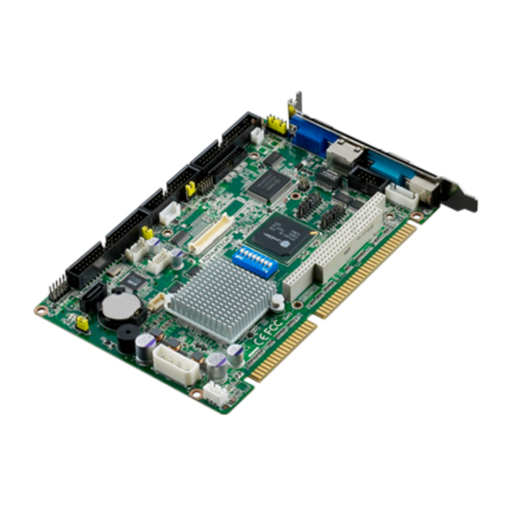
- Page 2 User Manual PCA-6743 DM&P Vortex86DX-800MHz SOC, ISA Half-size SBC, TTL, 10/100 Ethernet, CFC, On board memory...
- Page 3 The documentation and the software included with this product are copyrighted 2010 by Advantech Co., Ltd. All rights are reserved. Advantech Co., Ltd. reserves the right to make improvements in the products described in this manual at any time without notice.
-
Page 4: Declaration Of Conformity
Because of Advantech’s high quality-control standards and rigorous testing, most of our customers never need to use our repair service. If an Advantech product is defec- tive, it will be repaired or replaced at no charge during the warranty period. For out- of-warranty repairs, you will be billed according to the cost of replacement materials, service time and freight. -
Page 5: Packing List
Technical Support and Assistance Visit the Advantech web site at www.advantech.com/support where you can find the latest information about the product. Contact your distributor, sales representative, or Advantech's customer service center for technical support if you need additional assistance. Please have the following information ready before you call: –... -
Page 6: Table Of Contents
2.18.2 LVDS TFT LCD connector (LVDS1) (Optional) ......24 2.19 Panel Inverter Power (INV1) ..............25 2.20 Low Pin Count Header (LPC1)..............25 Table 2.10: LPC Module.............. 25 2.21 Serial ATA Interface (SATA1) ..............26 2.22 PC/104 connector (PC104) ..............26 PCA-6743 User Manual... - Page 7 Assignments......53 System I/O ports ..................54 Table C.1: System I/O ports............54 DMA Channel assignments ..............55 Table C.2: DMA Channel assignments........55 Interrupt assignments ................55 Table C.3: Interrupt assignments..........55 1st MB Memory map................56 PCA-6743 User Manual...
- Page 8 Table C.4: 1st MB Memory map ..........56 Appendix D Installing PC/104 Modules ....57 Introduction ..................... 58 Figure D.1 PC/104 module mounting diagram ......58 Figure D.2 PC/104 module dimensions (mm) (± 0.1)....59 PCA-6743 User Manual...
- Page 9 PCA-6743 User Manual viii...
-
Page 10: Chapter 1 General Information
Chapter General Information This chapter gives background information on the PCA-6743 ISA Half-size CPU Card. -
Page 11: Introduction
SVGA/LCD display controller (LCD and CRT displays) allows LCD screen resolutions up to 1024 x768 @ 18/24 bit LVDS/TTL (Optional) and CRT resolutions up to 1024 x 768 @ 24 bit true color. If you need any additional functions, PCA-6743 also supports a PC/104 connector for future upgrades. -
Page 12: Vga/Flat Panel Interface
Power supply voltage: Typical: +5V @ (4.75V~5.25V), 12V Power requirement: Max: 5V@1.44A,12V @0.04A Operating temperature: 0 ~ 60°C (32 ~ 140° F) Operating humidity: 0% ~ 90% relative humidity, non-condensing Weight: 0.27 Kg (0.59 lb) PCA-6743 User Manual... - Page 13 PCA-6743 User Manual...
-
Page 14: Chapter 2 H/W Installation
Chapter H/W Installation This chapter explains the setup procedures of the PCA-6743 hard- ware, including instructions on setting jumpers and connecting peripherals, switches, indicators and mechanical drawings. Be sure to read all safety precautions before you begin the installation procedure. -
Page 15: Jumper And Connector Locations
Jumper and Connector locations Figure 2.1 Jumper and Connector Locations (component side) Figure 2.2 Jumper and Connector Locations (solder side) PCA-6743 User Manual... -
Page 16: Jumpers And Connectors
JWDT1 Watchdog timer output selection JOBS1 HW Monitor Alarm JLVDS1 LVDS voltage selection JBK1 Backlight control selection LCD settings The following table lists the connectors on the PCA-6743. Table 2.2: Connectors Label Function JFP1(1-2) HDD LED JFP1(3-4) Power LED JFP1(5-6) -
Page 17: Setting Jumpers
A pair of needle-nose pliers may be helpful when working with jumpers. If you have any doubts about the best hardware configuration for your application, contact your local distributor or sales representative before you make any changes. Generally, you simply need a standard cable to make most connections. PCA-6743 User Manual... -
Page 18: Setting Details
2.3.1 Setting details Table 2.3: CMOS1 CMOSW Clear Setting Function 1-2 (Default) Normal operation Clear CMOS PCA-6743 User Manual... -
Page 19: Jsetcom2 Com2 Function Selection
Table 2.4: JSETCOM1 COM1 function selection JSETCOM2 COM2 function selection (Default) PCA-6743 User Manual... -
Page 20: Table 2.5: Jwdt1 Watchdog Timer Output Selection
3-5 closed (Default) System reset Table 2.6: JOBS1: HW Monitor Alarm Setting Function 7-9 closed (Default) Eable OBS alarm 7-9 open Diable OBS alarm Table 2.7: IR connector Setting Function Connecting 2-10 Connecting to external IR module PCA-6743 User Manual... -
Page 21: Table 2.8: Jlvds1 Lvds Voltage Selection
Table 2.8: JLVDS1 LVDS voltage selection Setting Function 1-2 Close (Default) +V_LCD voltage = 3.3V 2-3 Close +V_LCD voltage = 5V PCA-6743 User Manual... -
Page 22: Table 2.9: Jbk1 Backlight Control Selection
CPU card. Modern electronic devices are very sensitive to static electric charges. Use a grounding wrist strap at all times. Place all electronic components on a static-dissipative surface or in a static-shielded bag when they are not in the chassis. PCA-6743 User Manual... -
Page 23: Front Panel Connectors (Jfp1)
Front Panel Connectors (JFP1) There are several external switches to monitor and control the PCA-6743. IR Connector (JIR1) This connector supports the optional wireless infrared transmitting and receiving module. This module mounts on the system case. You must configure the setting through BIOS setup. -
Page 24: Ide Connector (Ide1)
If you install two drives, you will need to set one as the master and one as the slave by using jumpers on the drives. If you install only one drive, set it as the master. PCA-6743 User Manual... -
Page 25: Compact Flash Card Socket (Cf1)
Compact Flash card Socket (CF1) The board provides a CompactFlash card type I/II socket. The CompactFlash card shares a primary IDE channel. PCA-6743 User Manual... -
Page 26: Parallel Port Connector (Lpt1)
The parallel port is designated as LPT1, and is normally used to connect the CPU card to a printer. The PCA-6743 includes an onboard parallel port, accessed through a 26-pin flat-cable connector. The card comes with an adapter cable which lets you use a traditional DB-25 connector. -
Page 27: Usb Ports (Usb12 & Usb34)
USB Ports (USB12 & USB34) The PCA-6743 provides up to four ports of USB (Universal Serial Bus) interface, which gives complete Plug & Play and hot swapping for up to 127 external devices. The USB interface complies with USB Specification Rev. 2.0 support transmission rate up to 480 Mbps and is fuse-protected. -
Page 28: Serial Ports (Com1 & Com2 & Com34)
2.10 Serial Ports (COM1 & COM2 & COM34) The PCA-6743 offers four serial ports, COMD1 as COM1 (RS-232 (VE SKU)/ RS- 232/RS-422/RS-485 (F SKU) on real I/O) and COM2 as COM2 (RS-232(VE SKU)/ RS-232/RS-422/RS-485 (F SKU) on one 2.54mm pitch wafer box) and COM34 as COM3, COM4 (2*RS-232 (F SKU) on one 2.0mm pitch wafer box). -
Page 29: Ps/2 Keyboard / Mouse Connector (Kbms1 & 2)
2.12 VGA connector (VGA1) The PCA-6743 includes a VGA interface that can drive conventional CRT displays. VGA1 is a 12-pin, dual-inline header used for conventional CRT displays. A simple one-to-one adapter can be used to match VGA1 to a standard 15-pin D-SUB connec- tor commonly used for VGA. -
Page 30: Ethernet Connector (Lan1)
2.14 Front Panel LAN Indicate connector (LANLED1) This LED is active for LAN connects; PCA-6743 provides an external LAN LED Pin header for connecting to the front side of the chassis. With this convenient design users may know whether the LAN port is acting or not easily. Refer to Appendix A for detailed information on the pin assignments. -
Page 31: System Fan Connector (Sysfan1)
If fan is used, this connector supports cooling fans of 500mA (6W) or less. 2.16 Power connector (PWR1) If you prefer not to acquire power through the PCA-6743 backplane via the gold H- connectors, the big 4P power connector (PWR1) also provides power input connec- tors for +5 V, and +12 V. -
Page 32: Gpio Header (Gpio1)
The board supports 8-bit GPIO through GPIO connector. The 8 digital in- and out- puts can be programmed to read or control devices, with input or out- put defined. This GPIO is CMOS level. PCA-6743 User Manual... -
Page 33: Flat Panel Display Connector (Lcd1 & Lvds1)
LVDS (optional) and TTL can support resolutions of 640X480, 800X480, 800X600 and 1024X768. 2.18.1 TTL TFT LCD connector (LCD1) For PCA-6743, LCD1 consists of a 40-pin connector which can support 1024 x 768 @ 18/24-bit TTL TFT LCD panel. 2.18.2 LVDS TFT LCD connector (LVDS1) (Optional) For PCA-6743, LVDS1 consists of a 20-pin connector which can support 1024 x768 @ 18/24-bit LVDS TFT LCD panel for optional. -
Page 34: Panel Inverter Power (Inv1)
V power to the LCD display. 2.20 Low Pin Count Header (LPC1) PCA-6743 provides 14-Pins pin header for LPC module. Refer to Appendix A for detailed information on the pin assignments. Here are the LPC modules that you can choose as accessory. -
Page 35: Serial Ata Interface (Sata1)
2.21 Serial ATA Interface (SATA1) PCA-6743 (only F SKU) features a high performance one serial ATA interface (up to 150 MB/s) which eases cabling to hard drives with thin and long cables. Note! We found compatibility issue on Hitachi HDT721010SLA360, Seagate ST9320320AS and Seagate ST31500341AS, please notice! 2.22... -
Page 36: Bios Operation
Chapter BIOS Operation This chapter describes how to set BIOS configuration data. -
Page 37: Bios Introduction
CPUs from 386 through Pentium and AMD Geode, K7 and K8 (including multiple pro- cessor platforms), and VIA Eden C3 and C7 CPU. You can use Advantech’s utilities to select and install features to suit your designs for customers need. -
Page 38: Main Menu
Set Password Establish, change or disable password. Save & Exit Setup Save CMOS value settings to CMOS and exit BIOS setup. Exit Without Saving Abandon all CMOS value changes and exit BIOS setup. PCA-6743 User Manual... -
Page 39: Standard Cmos Features
Extended Memory The POST of the BIOS will determine the amount of extended memory (above 1MB in CPU’s memory address map) installed in the system. Total Memory This item displays the total system memory size. PCA-6743 User Manual... -
Page 40: Advanced Bios Feature
This item allows a user to enable / disable HDD with smart function support. Summary Screen Show [Disabled] Show all Mother Board information on POST. Boot Other Device The item allows user to boot up from other devices. PCA-6743 User Manual... -
Page 41: Advanced Chipset Features
This item allows a user to set VGA related features. – VGA monitor[CRT] This item allows to choose display on CRT, LCD, or displaying simultane- ously. – Panel Resolution Mode[AUTO] This item allows to change resolution – LCD backlight[00] This item allows to adjust LCD backlight. PCA-6743 User Manual... - Page 42 DMA Operating Clock [4MHz] USB Device Setting [Press Enter] This item allows users to set USB related features. – USB Controller [Enabled] This item allows to enable or disable USB co ntroller – USB Operation Mode [High Speed] PCA-6743 User Manual...
-
Page 43: Integrated Peripherals
This item is enabled or disabled that onboard of LAN controller. Onboard LAN ROM [Disabled] This item allows user to choose the way that LAN boot ROM work PDX-600 CPU Divided [[Divide 1] This item allows to do CPU speed divided 3.2.5 Integrated Peripherals PCA-6743 User Manual... - Page 44 IDE HDD Block Mode [Enabled] This item allows enabled or disabled that IDE block data transfer mode. It will speed up HDD data transfer of efficiency. BIOS default value suggest to "Enabled". KBC input clock [12 MHz] PCA-6743 User Manual...
- Page 45 This selection is available only if you select "ECP" or "ECP + EPP" in the Parallel Port Mode field. In ECP Mode Use DMA, you can select DMA channel 1, DMA channel 3. Leave this field on the default setting. PCA-6743 User Manual...
-
Page 46: Pnp/Pci Configurations
The item is designed to solve problems caused by some non-standard VGA cards. A built-in VGA system does not need this function. PCI IRQ Actived By [Level] The item allows users to choose level or edge. PCA-6743 User Manual... -
Page 47: Pc Health
[Load Optimized Defaults] loads the default system values directly from ROM. If the stored record created by the Setup program should ever become corrupted (and therefore unusable), these defaults will load automatically when you turn the PCA-6743 Series system on. PCA-6743 User Manual... -
Page 48: Set Password
You will see "Confirm Password". Type it again, and press <Enter>. Select Set Password again, and at the "Enter Password" prompt, please don’t enter anything; just press <Enter>. Select Save to CMOS and EXIT, type <Y>, then <Enter>. PCA-6743 User Manual... -
Page 49: Save & Exit Setup
3.2.10 Save & Exit Setup Note! Typing "Y" will quit the BIOS Setup Utility and save user setup value to CMOS. Typing "N" will return to BIOS Setup Utility. PCA-6743 User Manual... -
Page 50: Quit Without Saving
3.2.11 Quit Without Saving Note! Typing "Y" will quit the BIOS Setup Utility without saving to CMOS. Typing "N" will return to BIOS Setup Utility. PCA-6743 User Manual... - Page 51 PCA-6743 User Manual...
-
Page 52: Pin Assignments
Appendix Pin Assignments This appendix contains informa- tion of a detailed or specialized nature. -
Page 53: Front Panel Connectors (Jfp1)
HDD LED+ HDD LED- Power LED+ Power LED- Reset Switch 5 VSB (Reserved) ATX power button (Reserved) USB Ports (USB12 & USB34) Table A.2: USB Ports (USB12 & USB34) Signal USB Data1- USB Data2- USB Data1+ USB Data2+ PCA-6743 User Manual... -
Page 54: Serial Ports (Com2)
Serial Ports (COM2) Table A.3: Serial Ports (COM2) Signal RS232 RS422 RS485 TXD- Data- TXD+ Data+ RXD+ RXD- Serial Ports (COM34) Table A.4: Serial Ports (COM34) Signal Signal DCD3 DSR3 RTS3 CTS3 DTR3 DCD4 DSR4 RTS4 CTS4 DTR4 PCA-6743 User Manual... -
Page 55: Ps/2 Keyboard / Mouse Connector (Kbms2)
PS2 mouse data PS2 mouse clock Front Panel LAN Indicate connector (LANLED1) Table A.6: Front Panel LAN Indicate connector (LANLED1) Signal LAN_/ACTIVITY# LAN1_100# System FAN connector (SYSFAN1) Table A.7: System FAN connector (SYSFAN1) Signal +12 V FAN_TACH PCA-6743 User Manual... -
Page 56: Gpio Header (Gpio1)
Table A.9: TTL TFT LCD connector (LCD1) Signal Signal +V_LCD +V_LCD +V_LCD +V_LCD Vcon LCD_DATA0 LCD_DATA1 LCD_DATA2 LCD_DATA3 LCD_DATA4 LCD_DATA5 LCD_DATA6 LCD_DATA7 LCD_DATA8 LCD_DATA9 LCD_DATA10 LCD_DATA11 LCD_DATA12 LCD_DATA13 LCD_DATA14 LCD_DATA15 LCD_DATA16 LCD_DATA17 LCD_DATA18 LCD_DATA19 LCD_DATA20 LCD_DATA21 LCD_DATA22 LCD_DATA23 LCD_SCLK LCD_VSYNC LCD_DE LCD_HSYNC LCD_BACKON PCA-6743 User Manual... -
Page 57: Lvds Tft Lcd Connector (Lvds1)
Table A.10: LVDS TFT LCD connector (LVDS1) Signal Signal +V_LCD +V_LCD LVDS_TX0- LVDS_TX0+ LVDS_TX1- LVDS_TX1+ LVDS_TX2- LVDS_TX2+ LVDS_TX3- LVDS_TX3+ LVDS_CLK- LVDS_CLK+ A.11 Inverter power connector (INV1) Table A.11: Inverter power connector (INV1) Signal +12 V BACK_ON# Brightness +5 V PCA-6743 User Manual... - Page 58 Appendix Programming the Watchdog Timer This appendix contains informa- tion of how to program the Watch- dog Timer.
-
Page 59: Programming The Watchdog Timer
Introduction The PCA-6743’s watchdog timer can be used to monitor system software operation and take corrective action if the software fails to function within the programmed period. This section describes the operation of the watchdog timer and how to pro- gram it. -
Page 60: B.1.3 Example Program
F5h dx, al al, dx al, not 08h dx, al ;----------------------------------------------------------- dx, 2Eh ; Set timeout interval as 10 seconds and start counting al, F6h dx, al al,10 dx, al ;----------------------------------------------------------- dx, 2Eh; Lock W83627-DHG-P al, AAh PCA-6743 User Manual... - Page 61 08h dx, al ;----------------------------------------------------------- dx, 2Eh; Set timeout interval as 5 minutes and start counting al, F6h dx, al al, 5 dx, al ;----------------------------------------------------------- dx, 2Eh; Lock W83627-DHG-P al, AAh dx, al PCA-6743 User Manual...
-
Page 62: System Assignments
Appendix System Assignments This appendix contains informa- tion of all System assignments. -
Page 63: System I/O Ports
Monochrome display 3C0-3CF Reserved 3D0-3DF Color / Graphics monitor adapter 3E8-3EF Serial port 3 3F0-3F7 Diskette controller 3F8-3FF Serial port 1 481-483/487/489/48A/ DMA High page Registers 490-499 Instruction Counter Registers 4D0-4D1 Interrupt Edge / Level control Registers PCA-6743 User Manual... -
Page 64: Dma Channel Assignments
INT from co-processor IRQ 14 Primary IDE IRQ 15 Secondary IDE for CompactFlash IRQ 3 Communication ports (COM2) IRQ 4 Communication ports (COM1) IRQ 5 Communication ports (COM4) IRQ 6 Floppy Disk IRQ 7 Parallel port 1 (print port) PCA-6743 User Manual... -
Page 65: St Mb Memory Map
1st MB Memory map Table C.4: 1st MB Memory map Memory Address(Hex) Device E8000h-10001Fh BIOS Area D4000h-E7FFFh Available CC000h-D3FFFh Legacy USB C0000h-CBFFFh VGA BIOS B8000h-BFFFFh CGA/EGA/VGA text B0000h-B7FFFh Reserved for graphic mode usage A0000h-AFFFFh EGA/VGA graphics 00000h-9FFFFh Base memory PCA-6743 User Manual... - Page 66 Appendix Installing PC/104 Modules This appendix contains informa- tion of installing PC/104 modules.
-
Page 67: D.1 Introduction
Introduction The PCA-6743 PC/104 connectors give you the flexibility to attach PC/104 modules. Installing these modules on the PCA-6743 is quick and simple. The following steps show how to mount the PC/104 modules: Remove the PCA-6743 from your system, paying particular attention to the safety instructions already mentioned above. -
Page 68: Figure D.2 Pc/104 Module Dimensions (Mm) (± 0.1)
SA17 IOR* SD11 DACK7* SA16 DACK3* SD12 DRQ7 SA15 DRQ3 SD13 +5 V SA14 DACK1* SD14 MASTER* SA13 DRQ1 SD15 SA12 REFRESH* SA11 SYSCLK SA10 IRQ7 IRQ6 IRQ5 IRQ4 IRQ3 DACK2* BALE +5 V * active low PCA-6743 User Manual... - Page 69 No part of this publication may be reproduced in any form or by any means, electronic, photocopying, recording or otherwise, without prior written permission of the publisher. All brand and product names are trademarks or registered trademarks of their respective companies. © Advantech Co., Ltd. 2013...
- Page 70 Our company network supports you worldwide with offices in Germany, Austria, Switzerland, Great Britain and the USA. For more information please contact: FORTEC Elektronik AG FORTEC Elektronik AG Hauptniederlassung Büro West Lechwiesenstr. 9 Hohenstaufenring 55 86899 Landsberg am Lech 50674 Köln Telefon: +49 (0) 8191 91172-0 Telefon:...
Need help?
Do you have a question about the PCA-6743 and is the answer not in the manual?
Questions and answers