
Related Manuals for Advantech PCM-5825


Summary of Contents for Advantech PCM-5825
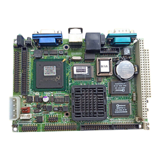
- Page 1 PCM-5825 NS Geode Single Board Computer with CPU, 4 COMs, VGA/LCD, Ethernet, and Audio Interface...
-
Page 2: Copyright Notice
Winbond is a trademark of WinbondElectronics Corp. NS is a trademark of National Semiconductor Inc. CHRONTEL is a trademark of Chrontel Inc. For more information on this and other Advantech products please visit our website at: http://www.advantech.com http://www.advantech.com/epc For technical support and service for please visit our support website at: http://support.advantech.com... - Page 3 Packing list Before you begin installing your card, please make sure that the following materials have been shipped: • 1 PCM-5825 Series all-in-one single board computer • 1 startup manual • 1 utility disk/CD, driver, and manual (in PDF format) •...
-
Page 4: Table Of Contents
1.3.5 Solid state disk ............6 1.3.6 Mechanical and environmental ......6 Board layout and dimensions ........7 Figure 1-1: PCM-5825 dimensions ..........7 Chapter 2 Installation ..........9 2.1 Jumpers and connectors ..........10 Table 2-1: Jumpers ..............10 Table 2-2: Connectors .............. - Page 5 2.7 IDE hard drive connector (CN15) ......17 2.7.1 Connecting the hard drive ........17 2.8 CompactFlash™ disk (CN24) ........18 2.9 Floppy drive connector (CN4) ........18 2.9.1 Connecting the floppy drive ........18 2.10 Parallel port connector (CN3) ......... 19 2.11 Keyboard and PS/2 mouse connector (CN21) ..
- Page 6 Chapter 3 Software Configuration ......27 3.1 Introduction ..............28 3.2 Utility CD disk ............... 28 Figure 3-1: Contents of the PCM-5825 utility disk ....28 3.3 VGA display software configuration ......29 Figure 3-2: BIOS VGA setup screen ........29 3.4 Connections for two standard LCDs ......
- Page 7 4.2.11 Save & exit setup ..........46 4.2.12 Exit without saving ..........46 Chapter 5 SVGA Setup ..........47 5.1 Introduction ..............48 5.1.1 Chipset ..............48 5.1.2 Display memory ........... 48 5.2 Installation of SVGA driver ......... 49 5.2.1 Installation for Windows 3.1 ......... 50 5.2.2 Installation for Cyrix MediaGX ......53 5.2.3 Installation for Windows NT ........
- Page 8 A.6 COM1 RS-232 serial port (CN19) ......86 Table A-6: COM1 RS-232 serial port ........86 A.7 COM3/COM4 Connector (CN2) ......87 Table a-7: COM3/ COM4 RS-232 series Ports ......87 A.8 Ethernet 100Base-T connector (CN20) ....87 Table A-8: Ethernet 100Base-T connector ......87 A.9 Auxilary peripheral power connector (CN1) ...
- Page 9 Figure C-2: PC/104 module dimensions (mm) (±0.1) .... 103 Table C-1: PC/104 connectors (CN14) ......... 104 Appendix D Programming the Watchdog Timer . 105 D.1 Programming the watchdog timer ......106 Appendix E Mechanical Drawings ....... 109 E.1 Component side ............110 E.2 Solder side ..............
-
Page 11: Chapter 1 General Information
General Information This chapter gives background informa- tion on the PCM-5825. Sections include: • Board specifications • Board layout and dimensions... -
Page 12: Introduction
4COM ports and 1-62sec Watchdog timer. It offers all the functions of an AT-compatible industrial computer on a single board and only occupies 3½" on a hard drive. The PCM-5825 comes with an embedded high-performance GX1-300 or GX1-233 processor on- board. -
Page 13: Features
Features • Ultra-compact size single board computer as small as a 3 1/2" hard disk drive (145 mm x 102 mm) • On-board NS GX1-300 or GX-233 CPU • Up to 256 MB system memory by SODIMM (SDRAM) • On-board VGA/LCD controller •... -
Page 14: Specifications
Specifications 1.3.1 Standard SBC functions • CPU: - Embedded NS GX1-300 PCM-5825-G0A2 • BIOS: AWARD 256 KB Flash memory • Chipset: NS CX5530 • System memory: One 144-pin SODIMM socket accepts up to 256 MB SDRAM • Enhanced IDE interface: Supports up to two EIDE devices. BIOS auto-detect, PIO Mode 3 or Mode 4 transfer, Ultra DMA33 mode (ATA-4) up to 33 MB/sec. -
Page 15: Local-Bus Flat Panel/Vga Interface
1.3.2 Local-bus flat panel/VGA interface • Chipset: NS CS5530A • Display memory: 1 ~ 4 MB share memory, set in BIOS • Display type: Supports CRT and TFT LCD displays. Can display CRT and flat panel simultaneously • Flat panel display mode: Panel resolution supports up to 1024 x 768 @ 16 bpp. -
Page 16: Solid State Disk
• Power supply voltage: +5 V (4.75 ~ 5.25 V) • Power consumption (typical) : +5 V @ 1.3 A (typical) (for PCM-5825 / GX1-300) +5 V @ 3 A (Max) • Operating temperature: 0 ~ 60° C (32 ~ 140° F) •... -
Page 17: Board Layout And Dimensions
Board layout and dimensions Figure 1-1: PCM-5825 dimensions Chapter 1 General Information... - Page 18 PCM-5825 User's Manual...
-
Page 19: Chapter 2 Installation
Installation This chapter tells how to set up the PCM-5825 hardware, including instruc- tions on setting jumpers and connecting peripherals, switches and indicators. Be sure to read all the safety precautions before you begin the installation proce- dure. -
Page 20: Jumpers And Connectors
The table below lists the function of each of the board jumpers and connectors: Table 2-1: Jumpers Label Function Audio power source setting Clear CMOS COM2 setting Watchdog timer action Buzzer setting LCD power selector PCM-5825 User's Manual... -
Page 21: Table 2-2: Connectors
Table 2-2: Connectors Label Function Auxiliary power connector (-5 V, -12 V) COM3/COM4 connector Parallel port connector Floppy disk connector Audio connector CPU fan power connector USB connector CD audio input connector CN11 ATX feature connector (standby power) CN12 IR connector (infrared) CN13 Main power connector (+5 V, +12 V) CN14... -
Page 22: Locating Jumpers
Locating jumpers Figure 2-1: Jumpers PCM-5825 PCM-5825 User's Manual... -
Page 23: Locating Connectors
Locating connectors 2.3.1 Component side Figure 2-2: Connectors - component side Figure 2-3: Connectors - solder side Chapter 2 Installation... -
Page 24: Setting Jumpers
If you have any doubts about the best hardware configuration for your application, contact your local distributor or sales representa- tive before you make any changes. Generally, you simply need a standard cable to make most connec- tions. PCM-5825 User's Manual... -
Page 25: Settings Details
2.4.2 Settings details Audio power source Closed Pins Voltage *1 - 2 System 5V 2 - 3 Regulated 5V Clear CMOS Closed Pins Result *1 - 2 3 V battery on 2 - 3 Clear CMOS COM2 selector Closed pins Result *1 - 2 RS-232... -
Page 26: Installing Dram (Sodimms)
2. Install the SODIMM card. Install the SODIMM so that its gold pins point down into the SODIMM socket. 3. Slip the SODIMM into the socket at a 45 degree angle and carefully fit the bottom of the card against the connectors. PCM-5825 User's Manual... -
Page 27: Ide Hard Drive Connector (Cn15)
Connecting drives is done in a daisy-chain fashion and requires one or two cables, depending on the drive size. All required cables are included in your PCM-5825 package. 1.8" and 2.5" drives need a 1 x 44-pin to 2 x 44-pin flat-cable connector. 3.5" drives use a 1 x 44-pin to 2 x 40-pin connector. -
Page 28: Compactflash™ Disk (Cn24)
PC system. Floppy drive connector (CN4) You can attach up to two floppy drives to the the PCM-5825 on- board controller. Any combination of 5¼” (360 KB and 1.2 MB) and/or 3½” (720 KB, 1.44 MB, and 2.88 MB) drives is possible. -
Page 29: Parallel Port Connector (Cn3)
If the keyboard is not present, the standard PC/AT BIOS will report an error or failure during the power-on self test (POST) after resetting the PC. The PCM-5825 board's BIOS standard setup menu allows you to select "All, But Keyboard" under the "Halt On"... -
Page 30: Power Connectors
CPU. 2.13 IR connector (CN12) The PCM-5825 provides an IrDA port for transfer rates of 115 kbps. This connector supports the optional wireless infrared transmitting and receiving module, which is mounted on the system case. -
Page 31: Cd Audio Input Connector (Cn9)
CD-ROM drive is suitable for connection to CN9. 2.14.3 Audio power source setting (J1) The PCM-5825 is designed to work with a single +5 V power supply as audio interfaces usually function under +5 V. However, most audio controllers require an independant +12 V power source since this avoids noise interference from other digital circuits. -
Page 32: Com2 Rs-232/422/485 Selection (Cn18)
However, if you wish to disable the port or change these parame- ters later, you can do this in the system BIOS setup. The table below shows the settings for the PCM-5825's serial ports. Table 2-5: Serial port default settings... -
Page 33: Vga Interface Connections
24-bit LCD panel. Power supply (+12 V) present on CN16 depends on the supply connected to the board. The PCM-5825 provides a bias control signal on CN16 that can be used to control the LCD bias voltage. It is recommended that the LCD bias voltage not be applied to the panel until the logic supply voltage (+5 V or +3.3 V) and panel video signals are stable. -
Page 34: Ethernet Interface Connections
Refer to Chapter 3 for details on connecting the two standard LCDs: Toshiba LTM10C042 and LTM 12C275A. 2.17 Ethernet interface connections The PCM-5825 is equipped with a high performance 32-bit PCI Ethernet interface which is fully compliant with IEEE 802.3u 10/100 Mbps CSMA/CD standards. -
Page 35: Watchdog Timer Configuration
IRQ11 * default setting 2.20 USB connectors (CN7) The PCM-5825 board provides two USB (Universal Serial Bus) interfaces which gives complete Plug and Play, and hot swaps for up to 127 external devices. The USB interfaces comply with USB specification Rev. 1.0 and are fuse protected. - Page 36 PCM-5825 User's Manual...
-
Page 37: Chapter 3 Software Configuration
Software Configuration This chapter details the software configu- ration information. It shows you how to configure the card to match your applica- tion requirements. Award system BIOS is covered in Chapter 4. Sections include: • LCD display configuration • Connections for two standard LCDs... -
Page 38: Introduction
Introduction The PCM-5825 system BIOS and custom drivers are located in a 256 KB, 32-pin Flash ROM device, designated U15. A single Flash chip holds the system BIOS and VGA BIOS. The display type can be configured via software. This method minimizes the number of chips and eases configuration. -
Page 39: Vga Display Software Configuration
Configure the LCD type as follows: 1. Apply power to the PCM-5825 with a color TFT display attached. This is the default setting for the PCM-5825. Make sure that the AWDFLASH.EXE and *.BIN files are located in the working drive. - Page 40 “Are you sure to program (Y/N)?” If you wish to continue, press Y. Press N to exit the program. The new VGA configuration will then write to the ROM BIOS chip. This configuration will remain the same until you run the AWDFLASH.EXE program and change the settings. PCM-5825 User's Manual...
-
Page 41: Connections For Two Standard Lcds
Connections for two standard LCDs 3.4.1 Connections for Toshiba LTM10C042 (640 x 480 TFT color LCD) Table 3-1: Connections for Toshiba LTM10C042 LTM10C042 PCM-5825 CN12 Name Name SHFCLK PD12 PD13 PD14 PD15 PD16 PD17 PD10 PD11 ENAB +5 V +5 V... -
Page 42: Connections For 800 X 600 Tft Color Lcd
3.4.2 Connections to Toshiba LTM12C275A (800 x 600 TFT color LCD) Table 3-2: Connections for Toshiba LTM12C275A LTM10C042 PCM-5825 CN12 Name Name NCLK SHFCLK PD12 PD13 PD14 PD15 PD16 PD17 PD10 PD11 ENAB M/DE +5 V +5 V PCM-5825 User's Manual... -
Page 43: Ethernet Interface Configuration
To configure the medium type, to view the current configuration, or to run diagnostics, do the following: 1. Power the PCM-5825 on. Make sure that the RSET8139.EXE file is located in the working drive. 2. At the prompt, type RSET8139.EXE and press <Enter>. The Ethernet configuration program will then be displayed. - Page 44 PCM-5825 User's Manual...
-
Page 45: Chapter 4 Award Bios Setup
Award BIOS Setup This chapter describes how to set BIOS configuration data. -
Page 46: System Test And Initialization
3. The CMOS memory has lost power and the configuration informa- tion has been erased. The PCM-5825 CMOS memory has an integral lithium battery backup. The battery backup should last ten years in normal service, but when it finally runs down, you will need to replace the complete unit. -
Page 47: Award Bios Setup
Award BIOS setup Award’s BIOS ROM has a built-in Setup program that allows users to modify the basic system configuration. This type of information is stored in battery-backed CMOS RAM so that it retains the Setup information when the power is turned off. 4.2.1 Entering setup Power on the computer and press <Del>... -
Page 48: Standard Cmos Setup
This standard Setup Menu allows users to configure system components such as date, time, hard disk drive, floppy drive and display. Once a field is highlighted, on-line help information is displayed in the left bottom of the Menu screen. Figure 4-2: CMOS setup screen PCM-5825 User's Manual... -
Page 49: Bios Features Setup
4.2.3 BIOS features setup By choosing the BIOS FEATURES SETUP option from the INITIAL SETUP SCREEN menu, the screen below is displayed. This sample screen contains the manufacturer’s default values for the PCM-5825 Series. Figure 4-3: BIOS features setup Chapter 4 Award BIOS Setup... -
Page 50: Chipset Features Setup
4.2.4 Chipset features setup By choosing the CHIPSET FEATURES SETUP option from the INITIAL SETUP SCREEN menu, the screen below is displayed. This sample screen contains the manufacturer’s default values for the PCM-5825. Figure 4-4: Chipset features setup PCM-5825 User's Manual... -
Page 51: Power Management Setup
4.2.5 Power management setup By choosing the POWER MANAGEMENT SETUP option from the INITIAL SETUP SCREEN menu, the screen below is displayed. This sample screen contains the manufacturer’s default values for the PCM- 5825. Figure 4-5: Power management setup Chapter 4 Award BIOS Setup... -
Page 52: Pnp/Pci Configuration
4.2.6 PnP/PCI configuration By choosing the PnP/PCI CONFIGURATION option from the Initial Setup Screen menu, the screen below is displayed. This sample screen contains the manufacturer’s default values for the PCM-5825. Figure 4-6: PnP/PCI configuration PCM-5825 User's Manual... -
Page 53: Integrated Peripherals
By choosing the INTEGRATED PERIPHERALS option from the INITIAL SETUP SCREEN menu, the screen below is displayed. This sample screen contains the manufacturer’s default values for the PCM-5825. The PANEL TYPE by default supports a 18-bit 640 x 480 TFT LCD panel display. Figure 4-7: Integrated peripherals... -
Page 54: Load Bios Defaults
LOAD BIOS DEFAULTS loads the default system values directly from ROM. If the stored record created by the Setup program becomes corrupted (and therefore unusable), these defaults will load automati- cally when you turn the PCM-5825 on. Confirm Password: Figure 4-8: Load BIOS defaults screen... -
Page 55: Change Password
4.2.9 Change password To change the password, choose the PASSWORD SETTING option form the Setup main menu and press <Enter>. 1. If the CMOS is bad or this option has never been used, a default password is stored in the ROM. The screen will display the following messages: Enter Password: Press <Enter>. -
Page 56: Auto Detect Hard Disk
This record is required for the system to operate. 4.2.12 Exit without saving Selecting this option and pressing <Enter> lets you exit the Setup program without recording any new values or changing old ones. PCM-5825 User's Manual... -
Page 57: Chapter 5 Svga Setup
SVGA Setup • Introduction • Installation of SVGA driver for Windows 95/98/NT... -
Page 58: Introduction
5.1.1 Chipset The PCM-5825 Series uses a Cyrix CX5530 chipset for its SVGA controller. It supports many popular 18-bit LCD displays and conven- tional analog CRT monitors. The VGA BIOS supports LCD. In... -
Page 59: Installation Of Svga Driver
Complete the following steps to install the SVGA driver. Follow the procedures in the flow chart that apply to the operating system that you are using within your PCM-5825 Series. Important: The following windows illustrations are examples only. You must follow the flow chart instructions and pay attention to the instructions which then appear on your screen. -
Page 60: Installation For Windows 3.1
5.2.1 Installation for Windows 3.1 1. In the Windows 3.1 Main screen, click on the "Windows Setup" icon. 2. In the "Windows Setup" window, choose "Options", then select "Change System Settings". PCM-5825 Series User's Manual... - Page 61 3. In the "Change System Settings" window, select the "Display" item. In the dropdown selection, select "Other display (Requires disk from OEM)". 4. Type in the correct path like the window below, where drive "D" is the CD ROM drive. For example, D:\ Biscuit\ 5820 \ VGA.100 \ Win31 Chapter 5 SVGA Setup...
- Page 62 5. Select the display type and preferred resolution, then click "OK". 6. Choose "Restart Windows" PCM-5825 Series User's Manual...
-
Page 63: Installation For Cyrix Mediagx
5.2.2 Installation for Cyrix MediaGX Certified drivers for Windows 95/980. Insert the disk into the CD-ROM drive. 1. Select "Start" then "Run". Type the correct path for the driver (like the example below) "D:\BISCUIT\5820\VGA\Win9xc_40" Click "OK" Chapter 5 SVGA Setup... - Page 64 2. Click "Finish" to continue. 3. Click "Next" to proceed to the next step. Click "Yes" after you read the license agreement. PCM-5825 Series User's Manual...
- Page 65 4. Follow the instructions which appear on the screen. 5. Insert the Win95/ 98 CD-ROM into the CD-ROM drive. Type the correct path for the Win9 x source file. Chapter 5 SVGA Setup...
- Page 66 6. Choose "Yes", then click "Finish" to restart the computer. PCM-5825 Series User's Manual...
-
Page 67: Installation For Windows Nt
5.2.3 Installation for Windows NT 1. a. Select "Start", "Settings" then "Control Panel" to get to the screen below. b. Double click on the "Display" icon. 2. a. Choose the "Settings" selection. b. Click the "Display Type" button. Chapter 5 SVGA Setup... - Page 68 3. Press the "Change..." button. 4. Click on the "Have Disk..." button PCM-5825 Series User's Manual...
- Page 69 5. a. Insert the disk into the CD-ROM drive. b. Type "D:\Biscuit\5820\VGA\WINNT\VGA.110\" c. Press "OK". 6. a. Select the highlighted item. b. Press "OK". Chapter 5 SVGA Setup...
- Page 70 7. Press "Yes" to proceed. 8. Press "OK" to reboot. PCM-5825 Series User's Manual...
- Page 71 9. a. Repeat Step 1 in this manual, select the "Settings" label. b. Adjust the resolution and color. c. Click "Test" to see the results. d. Click "OK" to save the settings. Chapter 5 SVGA Setup...
-
Page 72: Further Information
Further information For further information about the PCI/SVGA installation in your PCM-5820, including driver updates, troubleshooting guides and FAQ lists, visit the following web resources: Cyrix web site: www.national.com Advantech web sites: www.advantech.com www.advantech.com.tw PCM-5825 Series User's Manual... -
Page 73: Chapter 6 Audio
Audio • Introduction • Installation of audio driver for Windows 95/98/NT... -
Page 74: Introduction
Before installing the audio driver, please take note of the procedures detailed below. You must know which operating system you are using in your PCM-5825's, and then refer to the corresponding installation flow chart. Just follow the steps in the flow chart. You can quickly and successfully complete the installation, even though you are not familiar with instructions for Windows. -
Page 75: Installation For Windows 95/98
6.2.1 Installation for Windows 95/98 1.a. Select "Start", "Settings", "Control Panel", "System", "Device Manager". b. Click on "Other Devices". c. Remove items related to ESS 1869. 2.a. Select "Add new hardware". b. Click "Next". Chapter 6 Audio... - Page 76 3.a. Choose "No", then click "Next". 4. a. Select "Sound Video..." b. Click "Next" 5.a. Click "Have Disk" PCM-5825 User's Manual...
- Page 77 6. a. Insert the disc into the CD-ROM drive. b. Type the correct path D: 5825\VGA\Win9X\Audio" and click the "OK" button. D: 5825\VGA\Win9X\Audio 7. a. Select "ES1869 Control interface" 8. a. Click "Finish" to complete. Chapter 6 Audio...
- Page 78 9. Click "OK" 10. a. Insert Windows 9x CD. b. Type the path of your windows 9x disc and click "OK". D: 5825\VGA\Win9X\Audio 11. a. Click "Yes" to restart. PCM-5825 User's Manual...
-
Page 79: Installation For Windows Nt
6.2.2 Installation for Windows NT 1. a. Select "Start", "Settings", "Control Panel". b. Double click "Multimedia". 2. a. Select "Devices" item. b. Click "add". Chapter 6 Audio... - Page 80 3. Select the "Unlisted" item. b. Click "Ok". 4. a. Insert the disc into the CD-ROM drive. b. Type the correct path D: Biscuit\5825\VGA\Winn\Audio" and click the "OK" button. D:Biscuit\5825\VGA\Winn\Audio 5. a. Choose the highlighted section then click "OK". PCM-5825 User's Manual...
- Page 81 6. a. Set the I/O addresss. b. Click "Continue". 7. a. Set "Express Audio Configuration" b. Click "Ok" to restart. Chapter 6 Audio...
- Page 82 PCM-5825 User's Manual...
-
Page 83: Chapter 7 Pci Bus Ethernet Interface
PCI Bus Ethernet Interface This chapter provides information on Ethernet configuration. • Introduction • Installation of Ethernet driver for Windows 95/98/NT • Further information... -
Page 84: Introduction
Installation of Ethernet driver Before installing the Ethernet driver, note the procedures below. You must know which operating system you are using in your PCM-5825, and then refer to the corresponding installation flow chart. Then just follow the steps described in the flow chart. You will quickly and successfully complete the installation, even if you are not familiar with instructions for MS-DOS or Windows. -
Page 85: Installation For Windows 95/98
7.2.2 Installation for Windows 95/98 1. a. Select "Start", "Settings". "Control Panel". b. Double click "Network". 2. a. Click "Add" and prepare to install network functions. Chapter 7 PCI Bus Ethernet Interface... - Page 86 3. a. Select the "Adapter" item to add the Ethernet card. 4. a. Click "Have Disk" to install the driver. 5. a. Insert the CD into the D:\drive. b. Fill in "D:\5825\Ethernet.100\Win95\". c. Click "OK". D:\5825\Ethernet.100\Win95\ PCM-5825 User's Manual...
- Page 87 6. a. Choose the "Realtek" item. b. Click "OK". 7. a. Make sure the configurations of relative items are set correctly. b. Click "OK" to reboot. Note: The correct path for Windows 98 is: "D:\5825\Ethernet.100\Win98" Chapter 7 PCI Bus Ethernet Interface...
-
Page 88: Installation For Windows Nt
7.2.3 Installation for Windows NT 1. a. Select "Start", "Settings", "Control Panel". b. Double click "Network". 2. a. Choose the "Adapters" label. b. Click the "Add" button. PCM-5825 User's Manual... - Page 89 3. a. Press "Have Disk". 4. a. Type "D" b. Press "OK" 5. a. Insert the CD into D:\drive. b. Fill in "D:\5825\Ethernet.100\Winnt\". c. Click "OK". D:\5825\Ethernet.100\Winnt\ Chapter 7 PCI Bus Ethernet Interface...
- Page 90 6. a. Choose the "Realtek" item. b. Click "OK". 7. a. Make sure the configurations of relative items are set correctly. b. Click "OK" to reboot.. PCM-5825 User's Manual...
-
Page 91: Further Information
Further information Realtek website: www.realtek.com Advantech websites:www.advantech.com www.advantech.com.tw Chapter 7 PCI Bus Ethernet Interface... - Page 92 PCM-5825 User's Manual...
-
Page 93: Appendix A Pin Assignments
Pin Assignments This appendix contains information of a detailed or specialized nature. It includes: • CRT display connector • COM2 RS-232/422/485 serial port connector • Keyboard and mouse connector • Main power connector • IDE hard drive connector • COM1 RS-232 serial port •... -
Page 94: Crt Display Connector (Cn22)
Table A-1: CRT display connector Signal Signal VDDC GREEN BLUE DDCSDA H-SYNC V-SYNC DDCSCL A.2 COM2 RS-232/422/485 serial port (CN18) Table A-2: COM2 RS-232/422/485 series port RS-232 port RS-422 port RS-485 port TxD+ DATA+ TxD- DATA- RxD+ RxD- PCM-5825 User's Manual... -
Page 95: Keyboard And Mouse Connnector (Cn21)
A.3 Keyboard and mouse connnector (CN21) Table A-3: Keyboard and mouse connector Signal KB DATA MS DATA KB CLOCK MS CLOCK A.4 Main power connector (CN3) Table A-4: Main power connector Signal +12 V +5 V Appendix A Pin Assignments... -
Page 96: Ide Hard Drive Connector (Cn15)
37 HARD DISK 38 HARD DISK SELECT 0 SELECT 1 39 IDE ACTIVE* 40 GND 41 VCC 42 VCC 43 GND 44 N/C * low active A.6 COM1 RS-232 serial port (CN19) Table A-6: COM1 RS-232 serial port Signal PCM-5825 User's Manual... -
Page 97: Com3/Com4 Connector (Cn2)
A.7 COM3/COM4 Connector (CN2) Table a-7: COM3/ COM4 RS-232 series Ports Signal Signal DCD3 DSR3 RXD3 RTS3 TXD3 CTS3 DTR3 DCD4 DSR4 RXD4 RTS4 TXD4 CTS4 DTR4 A.8 Ethernet 100Base-T connector (CN20) Table A-8: Ethernet 100Base-T connector Signal XMT+ XMT- RCV+ RCV- Appendix A Pin Assignments... -
Page 98: Auxilary Peripheral Power Connector (Cn1)
Table A-10: Floppy drive connector Signal Signal DENSITY SELECT* INDEX* MOTOR 0* DRIVE SELECT 1* DRIVE SELECT 0* MOTOR 1* DIRECTION* STEP* WRITE DATA* WRITE GATE* TRACK 0* WRITE PROTECT* READ DATA* HEAD SELECT* DISK CHANGE* * low active PCM-5825 User's Manual... -
Page 99: Parallel Port Connector (Cn3)
A.11 Parallel port connector (CN3) Table A-11: Parallel port connector Signal STROBE* AUTOFD* ERROR* INIT* SLCTINI* Appendix A Pin Assignments... -
Page 100: Ir Connector (Cn12)
DATA 1+ A.14 Audio connector (CN5) Table A-14: Audio connector Signal Signal SPEAKER OUT R+ SPEAKER OUT R- SPEAKER OUT L+ SPEAKER OUT L- LINE OUT R LINE OUT L LINE IN R LINE IN L MIC IN PCM-5825 User's Manual... -
Page 101: Cd Audio Connector (Cn9)
A.15 CD audio connector (CN9) Table A-15: CD audio connector Signal CD audio control R CD audio control L A.16 CPU fan power connector (CN6) Table A-16: CPU fan power connector Signal +5 V +12 V Appendix A Pin Assignments... -
Page 102: 18-Bit Lcd Display Connector (Cn16)
Table A-17: Flat panel display connector Function Function +12 V +12 V 3.3V/5 (Vdd)** 3.3V/5 (Vdd)** PD10 PD11 PD12 PD13 PD14 PD15 PD16 PD17 SHFCLK DE (M) ENABKL VSAFE (ENAVDD) Vcc_LCD ** 3.3 V / 5 V can be set via J6 PCM-5825 User's Manual... -
Page 103: Compactflash™ Connector (Cn24)
A.18 CompactFlash™ connector (CN24) Table A-18: CompactFlash™ card connector (CN24) Signal Signal *CS0 *ATA SEL +5 V -IOCS16 *CD2 -CD1 -CS1 *VS1 -IORD *IOWR INTRQ +5 V *CSEL -VS2 *RESER IORDY *INPACK -REG *DASP -PDIAG * low active Appendix A Pin Assignments... - Page 104 PCM-5825 User's Manual...
-
Page 105: Appendix B System Assignments
System Assignments • System I/O ports • DMA channel assignments • Interrupt assignments • 1st MB memory map... -
Page 106: System I/O Ports
Color/graphics monitor adapter 3E8-3EF Series port 3 3F0-3F7 Diskette controller 3F8-3FF Serial port 1 Watchdog timer * PNP audio I/O map range from 220 ~ 250H (16 bytes) MPU-401 select from 300 ~ 330H (2 bytes) ** default setting PCM-5825 User's Manual... -
Page 107: Dma Channel Assignments
B.2 DMA channel assignments Table B-2: DMA channel assignments Channel Function Available Audio* Floppy disk (8-bit transfer) Parallel** Cascade for DMA controller 1 Audio* Available Available * Audio DMA default setting: DMA 1.5 Audio High DMA select: DMA 1.3 Audio Low DMA select: DMA 5.6.7 ** Parallel port DMA default setting: DMA 3 Parallel port DMA select: DMA 1.3 Appendix B System Assignments... -
Page 108: Interrupt Assignments
Serial communication port 1 IRQ 5 Audio* IRQ 6 Diskette controller (FDC) IRQ 7 Parallel port 1 (print port) Audio default setting: IRQ5 ** COM3 and COM4 share IRQ10 USB and Ethernet IRQs are automatically set by the system PCM-5825 User's Manual... -
Page 109: 1St Mb Memory Map
B.4 1st MB memory map Table B-4: 1st MB memory map Addr. range (Hex) Device F000h - FFFFh System ROM D800h - EFFFh Unused D000 - D400H Available C800h - D7FFh Ethernet ROM* C000h - C7FFh VGA BIOS B800h - BFFFh CGA/EGA/VGA text B000h - B7FFh Reserved for graphic mode usage... - Page 110 PCM-5825 User's Manual...
-
Page 111: Appendix C Installing Pc/104 Modules
Installing PC/104 Modules This appendix gives instructions for installing PC/104 modules. -
Page 112: Installing Pc/104 Modules
The PCM-5825's PC/104 connectors give you the flexibility to attach PC/104 modules. Installing these modules on the PCM-5825 is quick and simple. The following steps show how to mount the PC/104 modules: 1. Remove the PCM-5825 from your system, paying particular attention to the safety instructions already mentioned above. - Page 113 P C /1 0 4 M o u n tin g S u p p o rt F e m a le M a le P C /1 0 4 m o d u le P C M -5 8 20 S e rie s Figure C-1: PC/104 module mounting diagram 8 .9 8 2 .5...
-
Page 114: Table C-1: Pc/104 Connectors (Cn14)
SA10 IRQ7 — — IRQ6 — — IRQ5 — — IRQ4 — — IRQ3 — — DACK2* — — — — BALE — — +5 V — — — — — — — — * active low PCM-5825 User's Manual... -
Page 115: Appendix D Programming The Watchdog Timer
Programming the Watchdog Timer The PCM-5825 is equipped with a watchdog timer that resets the CPU or generates an interrupt if processing comes to a standstill for whatever reason. This feature ensures system reliability in industrial standalone or unmanned environments. -
Page 116: Programming The Watchdog Timer
You must write your program so that it writes 1 to I/O port 443 at an interval shorter than the timer's preset interval. The timer's intervals have a tolerance of ± 30%, so you should program an instruction that will refresh the timer about every second. PCM-5825 User's Manual... - Page 117 The following program shows how you might program the watchdog timer in BASIC: Watchdog timer example program X=Out &H443, 1 REM Enable and refresh the watchdog GOSUB 1000 REM Task #1, takes 1 second to complete X=Out &H443, 1 REM Refresh the watchdog GOSUB 2000 REM Task #2, takes 1 second to...
- Page 118 PCM-5825 User's Manual...
-
Page 119: Appendix E Mechanical Drawings
Mechanical Drawings... -
Page 120: Component Side
Component side Figure E-1: Board Dimensions component side PCM-5825 User's Manual... -
Page 121: Solder Side
Solder side Figure E-2: Board Dimensions solder side Appendix E Mechanical Drawings 1 1 1... - Page 122 PCM-5825 User's Manual...
Need help?
Do you have a question about the PCM-5825 and is the answer not in the manual?
Questions and answers