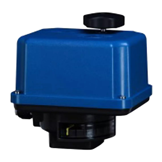
Summary of Contents for PS Automation PSR-E25
- Page 1 PSR-E Operating Instructions Version 2023/09/28 Art.No.: 8035621 ©2023 PS Automation GmbH Subject to changes...
-
Page 2: Table Of Contents
Contents Technical data ................................... 2 Type key .................................... 2 1. Symbols and safety ............................... 3 2. Usage as per specification ............................. 4 3. Storage ..................................4 4. Operating conditions..............................4 4.1 Installation position ..............................5 5. Manual operation ................................. 6 6. -
Page 3: Symbols And Safety
1. Symbols and safety Danger signs The following danger signs are used in this operating manual: Caution! There is a general risk of damage related to health and/or properties. Danger! Electrical voltages are present that may lead to death. Avoid personal or material damages by observing applicable regulations and safety standards! Other notes ... -
Page 4: Usage As Per Specification
2. Usage as per specification PSR-E quarter turn actuators are exclusively designed to be used as electric valve actuators. They are meant to be mounted on valves in order to run their motors. Any other use is considered to be non-compliant and the manufacturer cannot be held liable for any damage resulting from it. -
Page 5: Installation Position
Figure 1: Installation dimensions PSR-E Figure 2: Option PSR-E 24 VDC 6 Sek Outdoor usage: When using actuators in environments with high temperature fluctuations or high humidity, we suggest a heating resistor to be fitted to prevent the build-up of condensation within the enclosure. 4.1 Installation position The actuator can be installed vertically or horizontally or any position in between. -
Page 6: Manual Operation
The electric quarter-turn actuators Series PSR-E are designed to operate valves with 90° angular motion using the ON/ OFF mode. The PSR-E actuators are provided with a mechanical interface according to ISO 5211 for valve mounting. The motor torque is transmitted via spur gear, indirectly transmitted onto a double square drive bush. -
Page 7: Setting Of The Mechanical Stop
7. Setting of the mechanical stop There is one adjustable screw available for setting the mechanical limit of the 90° angular stroke. When setting the mechanical end positions, only the hand wheel may be used. Do not operate the actuator electrically! ... -
Page 8: Setting Of The Internal Limit Switches
8.1 Setting of the internal limit switches Ensure that the mains supply is secured against accidental switching-on! The limit switches are pre-adjusted in the factory. An additional adjustment of the two lower switching cams is normally not necessary. If you wish to adjust the limit switches yourself, please follow these instructions: ... - Page 9 Turn the cam of the OPEN limit switch (Figure 8Fehler! Verweisquelle konnte nicht gefunden werden., Pos. A) with a suitable screw driver (4 mm blade width) counter-clockwise until the micro switch is heard to click. Check the switching position and repeat the adjustment if necessary.
-
Page 10: Electric Supply
9. Electric supply Switch mains off before starting to work! Connect acc. to wiring diagram on the main frame. Mains connection cables must be dimensioned suitably to accept the maximum current requirement of the actuator and correspond to IEC 227 and IEC 245. The yellow-green coloured cables may be used only for connecting to earth. -
Page 11: Commissioning
PE Earth connection on housing plate has to be connected! Ensure that all connecting cables are stripped to the correct length so that they are protected against electric shock. 10. Commissioning Drive the actuator into an intermediate stroke position using the hand wheel. ... -
Page 12: Appendix
13. Appendix 13.1 Accessories Various options are available in order to adapt the actuators to the various service conditions. A list of accessories for each actuator type is shown on the actuator data sheet. Accessories / Options 230 VAC 1~ 115 VAC 1~ 24 VAC 24 VDC... -
Page 13: Ce Declaration Of Conformity
13.2 CE Declaration of Conformity... -
Page 14: Ca Declaration Of Conformity
13.3 CA Declaration of Conformity... - Page 15 Our representatives: Italy India PS Automazione S.r.l. PS Automation India Pvt. Ltd. Via Pennella, 94 Srv. No. 25/1, Narhe Industrial Area, I-38057 Pergine Valsugana (TN) A.P. Narhegaon, Tal. Haveli, Dist. Tel.: <+39> 04 61-53 43 67 IND-411041 Pune Fax: <+39> 04 61-50 48 62 Tel.: <+ 91>...


Need help?
Do you have a question about the PSR-E25 and is the answer not in the manual?
Questions and answers