
Related Manuals for PS Automation PS-AMS Series


Summary of Contents for PS Automation PS-AMS Series
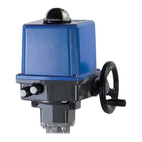
- Page 1 Operating Instructions PS-AMS Series PSQ Subject to changes! Version 2022/09/27 ©2022 PS Automation GmbH 1 ...
-
Page 2: Table Of Contents
Table of Contents 1. Symbols and safety .............................. 3 2. Usage as per specification ........................... 4 3. Storage ................................ 4 4. Operating Conditions and Installation Position .................... 4 4.1 Operating Conditions ............................ 4 4.2 Installation Position ............................ 5 5. Operating Principle .............................. 6 6. Manual Operation ............................... 6 7. Mechanical Mounting ............................ 7 7.1 Safety Note .............................. 7 7.2 Valve Mounting PSQ103‐1503AMS ........................ 7 7.3 Valve Mounting PSQ2003/2803AMS ...................... 8 8. Electrical Connection ............................ 8 8.1 Safety Note .............................. 8 8.2 Wiring Arrangements ............................. 9 8.3 Electric Wiring .............................. 9 8.3.1 Mains Supply ............................. 9 8.3.2 Input Terminals ............................ 13 8.3.3 Output Terminals ............................ 13 8.3.4 Fieldbus interface (optional) ........................ 14 8.4 Accessories .............................. 14 8.4.1 Space Heater (optional) .......................... 14 8.4.2 Adjusting Additional Position Switches (optional) ... -
Page 3: Symbols And Safety
1. Symbols and safety General dangers of non‐compliance with safety regulations PS‐AMS PSQ actuators are built at state‐of the art technology and are safe to operate. Despite of this, the actuators may be hazardous if operated by personnel that has not been sufficiently trained or at least instructed, and if the actuators are handled improperly, or not used as per specification. This may cause danger to life and limb of the user or a third party, damage the actuator and other property belonging to the owner, reduce safety and function of the actuator. To prevent such problems, please ensure that these operating instructions and the safety regulations in particular have been read and understood by all personnel involved in the installation, commissioning, operation, maintenance and repair of the actuators. Basic safety notes The actuators may only be operated by skilled and authorized operating personnel. Make sure to follow all security advices mentioned in this manual, any national rules for accident prevention, as well as the owner´s instructions for work, operation and safety. The isolating procedures specified in these Operating Instructions must be followed for all work pertaining to the installation, commissioning, operation, change of operating conditions and modes, maintenance, inspection, repair and installation of accessories Before opening the actuator cover, ensure that mains supply is isolated and prevented from unintended re‐ connection. Areas that can be under voltage have to be isolated before working on them. Ensure that the actuators are always operated in faultless condition. Any damage or faults, and changes in the operational characteristics that may affect safety, must be reported at once. Danger signs The following danger signs are used in this operating manual: Caution! There is a general risk of damage related to health and/or properties. Danger! Electrical voltages are present that may lead to death. Life threatening risks may occur ... -
Page 4: Usage As Per Specification
Other notes The motor surface temperature may rise when maintaining, inspecting and repairing the actuator immediately after the operation. There is a danger of burning the skin! Always consult the relevant operating instructions when mounting PS accessories or operating the actuator with PS accessories. Connections for signal in‐ and output are double isolated from circuits that can be under dangerous voltage. 2. Usage as per specification PS‐AMS PSQ quarter turn actuators are exclusively designed to be used as electric valve actuators. They are meant to be mounted on valves in order to run their motors. Any other use is considered to be non‐compliant and the manufacturer cannot be held liable for any damage resulting from it. The actuators can only be used within the limits laid out in the data sheets, catalogues and other documents. Otherwise, the manufacturer cannot be held liable for any resulting damage. Usage as per specification includes the observance of the operating, service and maintenance conditions laid down by the manufacturer. Not to be regarded as usage as per specification are mounting and adjusting the actuator as well as servicing. Special precautions have to be taken while doing this! The actuators may only be used, serviced and repaired by personnel that is familiar with them and informed about potential hazards. The specific regulations for the prevention of accidents have to be observed. Damages caused by unauthorized modifications carried out on the actuators are excluded from the manufacturer's liability. Supply voltage may only be switched on after the proper closure of the main cover or terminal box. 3. Storage For appropriate storage, the following instructions have to be met: Only store the actuators in ventilated, dry rooms. Store the actuators on shelves, wooden boards, etc., to protect them from floor moisture. Cover the actuators with plastic foil to protect them from dust and dirt. ... -
Page 5: Installation Position
PSQ103‐1503AMS PSQ2003/2803AMS figure 1: Outside dimensions Actuator Type A B C D E F G H I PSQ103AMS ... -
Page 6: Operating Principle
5. Operating Principle The quarter‐turn actuators PS‐AMS PSQ are designed for the use as electric valve actuators. Mounting to the valve is done by a mounting flange as per ISO5211, plus an exchangeable drive bushing with an inside contour as per the valve shaft. Mechanical power is created by a 24 volts DC‐motor which is controlled from the electronics via pulse width modulation (PWM). Absolute encoded feedback comes from a precision potentiometer. The motor torque is transmitted through a reducing spur gear to a planetary gear set. Output is a centre gear with a multi‐toothed inner profile to accept the drive bushing. During power failure and adjustment work the actuators can be emergency‐operated via the handwheel (see chapter 6. Manual Operation) except when using the fail‐safe unit PSCP. 6. Manual Operation A handwheel is provided to operate the actuator in case of power failure or for valve adjustment. PS‐AMS PSQ actuators are supplied with handwheel loosely added. Before operation it has to be fitted as shown below. figure 3: Mounting the handwheel ... -
Page 7: Mechanical Mounting
Caution! The handwheel should not be used in ongoing motor operation, as the actuator tries to compensate the deviation in position, depending on the operating mode selected. If a fail-safe unit type PSCP (option) is installed, the handwheel can’t be used, as the actuator drives back to the failsafe position. 7. Mechanical Mounting 7.1 Safety Note Beware of mechanical hazards due to electrically powered actuator components! With the actuator powered electrically, operating the unit holds the danger of crushing your fingers, damaging the actuator and/or the valve. -
Page 8: Valve Mounting Psq2003/2803Ams
7.3 Valve Mounting PSQ2003/2803AMS The PS‐AMS PSQ actuators are provided with flange F16 according to ISO 5211 for valve mounting. Connection to the valve shaft is made with a 55 mm double square. Delivery of the actuator includes two components: the gearbox and the actuator itself (already pre‐mounted). Use the position indicator at the gearbox to ensure the correct position of the actuator. Adapt it to the valve position by handwheel. In the best case, the position of the valve should be open or closed during mounting. Drive the actuator in the same end position manually. If the gearbox and actuator are in the same position, mount the actuator on the valve (if necessary, mount the adaptation of the valve shaft on the 55 mm double square first). Adapt the accurate mounting position by handwheel to insert the screws in the mounting flange. Tighten the screws in a diagonal sequence. 8. Electrical Connection 8.1 Safety Note When performing electric work on this unit, the local accident prevention regulations must be followed. Observe EN 60204‐1 (VDE 0113 part 1) to ensure human safety, integrity of the assets as well as the proper functioning of the unit. Electric supply lines must be dimensioned for the peak current of the unit and comply with IEC 227 and IEC 245. Yellow‐and‐green coded cords may only be used for connection to protective earth. When leading wires through the cable glands on the actuator, their minimum bending radius has to be considered. The electric actuators PS‐AMS PSQ are not fitted with an internal electric isolator, hence a switching device or circuit breaker must be integrated in the facility. It should be installed close to the actuator and should be easy to access for the user. It is important to mark the circuit breaker as this actuator‘s isolator. Electric installations and over‐current protection devices must be conform to the standard IEC 364‐4‐41, protective class I resp. DIN IEC 60364‐4‐44 according to the overvoltage category of the actuator. Please protect all of the power supply and control cables in front of the terminals mechanically by using suitable measures against unintentional loosening. Never install the power supply and the ... -
Page 9: Wiring Arrangements
8.2 Wiring Arrangements Depending on order specification, the PS‐AMS PSQ are supplied with two different wiring arrangements. Wiring to the Main Board: Electric wiring is made to terminals on the main board inside the actuator. Accordingly, the cover has to be opened for wiring. Wiring to Terminal Box: Electric wiring is made inside a separate box mounted to the actuator. Take off the cover from the box and fit the wires to the screwed terminals at the back of the plug modules. 8.3 Electric Wiring 8.3.1 Mains Supply Isolate the power supply. Safeguard the line against unauthorized and unintended restarting. Attention! Observe precautions for handling. Ground the actuator. Before opening the cover, touch grounded housing parts. ... - Page 10 Wiring to the main board: Wiring to the terminal box: figure 9: Open the terminal box figure 7: Open the cover Open the cover of the terminal box. Insert the Open the cover. Insert the cable into the actuator cable through the cable glands to the inside of the via the cable glands. cover. plug module ...
- Page 11 Ab figure 11: Wiring diagram for wiring to the main board ...
- Page 12 figure 13: Electric terminals with local control PSC.2 with 3‐phase AC Caution: Please observe the supply voltage and the maximum power consumption of the actuator as indicated on the actuator‘s name plate! Close the cover of the actuator: Close the cover of the terminal box: ...
-
Page 13: Input Terminals
8.3.2 Input Terminals 8.3.2.1 Set‐Value Terminals 1 through 3 are used to receive a parameterisable modulating set‐value for control operation within the range of 0‐20 mA or 0‐10V. 8.3.2.2 Sensor Feedback for Process Controller (optional) Terminals 15 through 17 (main board) resp. 10 through 12 (terminal box) are used to receive a process sensor‘s feedback to the ‐ optional ‐ process controller, in the parameterisable range of 0‐20 mA or 0‐10 V. Caution! The following binary input terminals (8.3.2.3 & 8.3.2.4) have priority over the modulating set‐value. If the actuator is parameterised for modulating service, these set‐value settings are disregarded in case a binary signal is applied. Only after disconnection of the binary signal the actuator will reposition according to the set‐ value applied. 8.3.2.3 Binary Input Terminals 9 through 11 (main board) resp. 17 through 19 (terminal box) are for binary open/close signals. Standard voltage level is 24 V to 230 V; see wiring diagram. The actuator is then driven in 3‐point service. 8.3.2.4 Fail‐safe port for Binary Input (optional) The fail‐safe port of the terminals 12 and 13 (main board) resp. 25 and 26 (terminal box) allows to drive the actuator to a parameterised safety position by applying a voltage of 24 V to 230 V. 8.3.3 Output Terminals 8.3.3.1 Active Position Feedback Active position feedback is adjustable within the range of 0‐20 mA or 0‐10 V. Main board: terminals 4 ‐ 6 Terminal box: terminals 4 ‐ 6 8.3.3.2 Additional Position Switches (optional) The activation points of the optional position switches can be mechanically adjusted via two cams. The switches can be accessed as potential‐free changeover contacts. The standard switches with silver contacts are rated to 230 VAC/5 A. Special switches with gold plated contacts for low power (up to 100 mA and 30V) are available on request. Limit switch board: terminals X6 / 1‐3 or X6 / 4‐6 respectively Terminal box: terminals 22/27/28 or 23/29/30 respectively 8.3.3.3 Voltage Feed to Process Sensor (optional) Terminals 14 and 17 provide an unregulated output voltage of 21 to 40 VDC at maximum 100 mA to feed an external process sensor. ... -
Page 14: Fieldbus Interface (Optional)
Main board: terminals 7 + 8 Terminal box: terminals 20 + 21 8.3.4 Fieldbus interface (optional) Optionally a fieldbus interface can be fitted to the AMS‐actuator, with wiring to a terminal block or an external socket. ‐> See special operating instruction for AMS‐Fieldbus. 8.4 Accessories 8.4.1 Space Heater (optional) Actuators PS‐AMS PSQ can be fitted with a space heater. When using actuators in environments with high temperature fluctuations or high humidity, we suggest a heating resistor be fitted to prevent the build‐up of condensation within the enclosure. In actuators PS‐AMS the space heater is powered via the power supply of the actuator does not have to be fed separately. For retro‐fitting the heating resistor, wiring of the two cables has to be made to the terminals on the main board as per the pictures. figure 16: Mounting and connecting of the ... -
Page 15: Status Display / Operating Element / Communication
3 2 The cams for activating the switches are mounted on a shaft by means of a friction coupling. They are X6 adjustable by a screwdriver with a small end, using the bride (3) as support. At actuators closing clockwise, the lower cam (1) activates the switch for closing direction, the upper cam (2) for opening direction. 1 figure 18: Adjusting the cams 9. Status Display / Operating Element / Communication 9.1 Status LEDs ... -
Page 16: Operation
10. Operation All internal parameters, like required motor torque, actual position, functional status, etc., are being permanently monitored during operation of the actuator PS‐AMS. This ensures that the actuator positions with optimum accuracy, and closes the valve always tight. Deviations can be read out via communication software PSCS or via local control PSC.2 (see respective instruction manuals), or can be displayed to the control room using the fault indication relay. This provides maximum safety of the process. Cut‐offs of the PS‐AMS actuators can be adjusted to meet the valve function in an optimum way by using the communication software PSCS (using a special interface cable, or optionally Bluetooth connection). This will result in different behaviour of the actuator. In case a position is surpassed or not reached, this can be read out via the Fault Indication Relay or via the communication software PSCS. 10.1 Cut‐off by Force / Torque The actuator delivers the programmed maximum force / torque each time when driving to this end position. If the closing point inside the valve dislocates, e.g. when a seat gasket wears, then the actuator will drive further in its possible actuation range to try to reach the programmed force / torque. 10.2 Cut‐Off by Position automatically In normal operation, the actuator will stop at the position which was found at a mechanical stop in the valve or the actuator during Automatic Commissioning. If the closing point inside the valve dislocates, the actuator will NOT follow this dislocation but it will always stop at the point initially found. 10.3 Cut‐Off by Position In normal operation, the actuator will stop at the point which was defined by Manual Commissioning. This position is not depending on any mechanical stop inside valve or actuator. 11. Commissioning The actuator is shipped in the „not commissioned“ condition with the green LED flashing slowly. There will be no response to any input (set value or open/close signal). To make the actuator operational, it has to be commissioned to a valve. Depending on the type of cut‐offs programmed (see 10.1), there are two ways to do commissioning: ‐ Automatic commissioning is done if at least one of the cut‐offs is set to be “by force/torque” or “by position automatically”. ‐ Manual commissioning has to be made in case both cut‐offs are “by position”, either via software PSCS or via control box PSC.2. Caution! Electrical operation of the actuator is allowed only after mounting to a valve! ... -
Page 17: Automatic Commissioning
11.1 Automatic Commissioning This is performed if at least one of the cut‐offs is set to be “by force/torque” or “by position automatically”. During automatic commissioning the actuator goes through the full programmed valve stroke / angle automatically. Parameters specific to the valve are being measured and calculated values are permanently stored in the actuator. At the same, set value and position feedback range are scaled. To enable Automatic Commissioning, a mechanical stop is required in at least one end position (usually the closed position) of the valve. This mechanical stop can be either given by design of the valve, or it may be adjusted by the stop screws of the actuator (only when cut‐off “by position automatically“ is programmed). 11.1.1 Adjusting the Mechanical Stops PSQ103‐1503AMS Shown is the adjustment of a mechanical stop in closing direction for a valve closing clockwise. When adjusting a mechanical stop, drive the actuator only by handwheel, not electrically! Remove the protection cap (figure 22, item 3) from either stop screw. Unscrew both hexagon sockets anti‐clockwise by approximately 5 turns. Move the actuator to the closed position by turning the handwheel clockwise. Turn stop screw for closed position (figure 22, item 1) to the stop. ... -
Page 18: Commissioning Procedure
11.1.3 Commissioning Procedure Ensure that all mechanical and electrical Commissioning button connections have been made properly. Switch on power supply. Unscrew the side cap for the actuator’s main cover and press the commissioning button with an insulating pin for about 3 seconds. figure 24: Commissioning button Caution! The actuator will now travel through the full valve angle! ... -
Page 19: Additional Information
11.1.5 Additional information Note If the actuator is stalled during the automatic commissioning run BEFORE reaching a desired position‐dependent cut‐ off, it will then store the so‐obtained stroke. Note If, as a result of automatic commissioning, no force/torque limit is found, or if a stroke below the minimum allowed stroke (10° in standard version) is found, the commissioning run will be aborted. The actuator returns to the “not commissioned” condition (i.e. green LED flashing slowly), even if the actuator had been initialized correctly before that. Note Automatic commissioning can be started via software PSCS ‐> See relevant operation manuals Caution! ... -
Page 20: Status Messages
12. Status messages 12.1 Fault indicator relay Fault messages can be transmitted to the control room with a maximum load of 24 VDC/100 mA via a closing contact at terminals 7 and 8. The messages can be parameterized via software PSCS. The contact on terminals 7 and 8 is closed when there is no fault and the drive is supplied with power. ‐> See relevant manuals PS‐AMS PSCS 12.2 Tracing faults See the table on page 22 for explanation of the blinking codes of the status‐LEDs. 13. Maintenance and Repair Maintenance Under the conditions of use as per specification as lined out in the data sheet, the PS‐AMS actuators are free of maintenance. All gears are lubricated for their service life and do not require to be re‐lubricated. Cleaning Clean the actuators with a dry soft cloth and do not use any cleaning agent. Do not use any coarse or abrasive materials. 14. Safety on Transportation For transportation and storage all cable glands and connection flanges have to be closed to prevent ingress of moisture and dirt. A suitable method of packaging is required for transporting to avoid damage of coating and any external parts of the actuator. ... -
Page 21: Accessories
15. Accessories Potential‐free additional position switches with silver contacts (0.1 Add'l Position Switches 2WE A ‐ 5 A switching current) Add'l Position Switches 2WE Potential‐free additional position switches with gold contacts (0.1 Gold Gold mA ‐ 100 mA switching current) Integrated process Enables the autonomous control of a process so that an external controller controller is not required. Emergency power supply based on supercapacitors, safety Fail‐Safe* PSCP position OPEN, CLOSED or free defined position Digital transmission of nominal and actual value per mill or percent, report of monitoring and diagnostic data using Profibus Fieldbus Interface* DP (PSPDP) or CANOpen (PSCA) interfaces, additional interfaces available on request Illuminated display to show the actuator status and lockable ... -
Page 22: Tracing Faults
16. Tracing faults Red LED Green LED Status Probable reasons Possible remedy x x Actuator does not 1) No supply voltage applied 1) Check mains supply respond, both LEDs are 2) The applied voltage does not 2) Apply correct supply voltage off match the actuator voltage on the tag plate x x Actuator does not drive 1) Actuator not correctly ... - Page 23 Faults within the Probable reasons Possible remedy actuator’s environment 3) No process sensor signal available x x Actuator drives into a 1) Signal is applied to the 1) Disconnect the signal preset position binary fail‐safe input 2) Check supply voltage 2) Supply voltage failure on actuators with optional PSCP ...
-
Page 24: Ce Declaration Of Conformity
17. CE Declaration of Conformity 24 ... -
Page 25: Ca Declaration Of Conformity
18. CA Declaration of Conformity 25 ... - Page 26 Our representatives: Italy India PS Automazione S.r.l. PS Automation India Pvt. Ltd. Via Pennella, 94 Srv. No. 25/1, Narhe Industrial Area, I‐38057 Pergine Valsugana (TN) A.P. Narhegaon, Tal. Haveli, Dist. Phone: <+39> 04 61‐53 43 67 IND‐411041 Pune Fax: <+39> 04 61‐50 48 62 Phone: <+ 91> 20 25 47 39 66 E‐mail: info@ps‐automazione.it Fax : <+ 91> 20 25 47 39 66 E‐mail : sales@ps‐automation.in www.ps‐automation.in To find out more about all our sales partners and subsidiaries please scan the QR code below or visit our website: https://www.ps‐automation.com/ps‐automation/locations/?lang=en ...
Need help?
Do you have a question about the PS-AMS Series and is the answer not in the manual?
Questions and answers