Advertisement
Quick Links
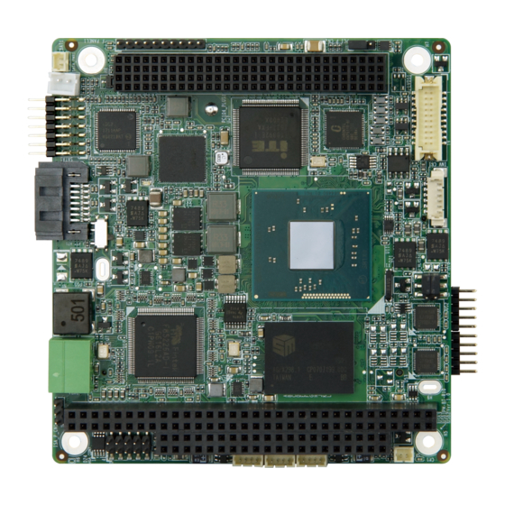
PC/104-Plus SBC with Intel® Atom™/Celeron® on-board SoC with
DDR3L, VGA, LVDS, GbE, USB 2.0, SATA 3Gb/s,
Quick Installation Guide
Package List
PM-BT package includes the following items:
1 x PM-BT single board computer
1 x COM port cable
1 x LAN cable
1 x SATA cable kit
1 x Single-port USB cable
1 x VGA cable
RS-232/422/485 and 5V DC input, RoHS
PM-BT
Version 1.0
Jun 15, 2018.
©2018 Copyright by IEI Integration corp.
All rights reserved.
1
Advertisement

Related Manuals for IEI Technology PM-BT-E38xx1W2-R10 Series


Summary of Contents for IEI Technology PM-BT-E38xx1W2-R10 Series
- Page 1 PC/104-Plus SBC with Intel® Atom™/Celeron® on-board SoC with DDR3L, VGA, LVDS, GbE, USB 2.0, SATA 3Gb/s, RS-232/422/485 and 5V DC input, RoHS PM-BT Quick Installation Guide Version 1.0 Jun 15, 2018. Package List PM-BT package includes the following items: 1 x PM-BT single board computer ...
-
Page 2: Specifications
Specifications SoC: Intel® Atom™ E3845 on-board SoC (1.91GHz, quad-core, 2MB cache, TDP=10W) Intel® Atom™ E3827 on-board SoC (1.75GHz, dual-core, 1MB cache, TDP=8W) Intel® Atom™ E3826 on-board SoC (1.46GHz, dual-core, 1MB cache, TDP=7W) Intel® Atom™ E3825 on-board SoC (1.33GHz, dual-core, 1MB cache, TDP=6W) Intel®... - Page 3 Internal I/O Interface: 1 x SATA 3Gb/s with 5V SATA power connector 3 x USB 2.0 (1x4 pin, P=1.25) 2 x RS-232/422/485 (2x5, P=2.0) Storage: On-board SSD (optional, support by request) Front Panel: 1 x 10-pin header, P=2.0 (power LED, HDD LED, power button and reset button) ...
-
Page 4: Ordering Information
Weight: GW: 500g / NW 120g CE/FCC compliant All the drivers and One Key Recovery IEI Resource Download Center utility for the PM-BT are available on IEI https://download.ieiworld.com Resource Download Center. Type PM-BT and press Enter to find all the relevant software, utilities, and documentation. - Page 5 33403-000015-RS: PC104 plus spacer (For PCI) 120 Pin socket connector 33403-000016-RS: PC104 plus spacer (For ISA) 64+40 Pin socket connector NOTE: ISA Limitation of PM-BT Due to the limitation of Intel® Bay Trail processors, the PM-BT does not support the following features: Bus Master Cycles LPC Memory Mapped Transactions...
-
Page 6: Jumpers Setting And Connectors
Jumpers setting and connectors LABEL FUNCTION BAT1 Clear COMS Setup J_ATX_AT1 Select ATX or AT Mode J_VLVDS1 LVDS VDD Power Selection LVDS Panel Resolution Selection PCI_P_CN1 PCI Power Voltage Selection ISA_P_CN1 ISA Power Voltage Selection ( External Input ) LAN1 LAN Port PWR1 DC +5V Power IN... - Page 7 J_VLVDS1: LVDS VDD Power Selection PIN NO. DESCRIPTION Short 1 - 3 Back-light Enable +3.3V (default) Short 2 - 4 Set The Voltage Level Of Panel To +3.3V (default) Short 3 - 5 Back-light Enable +5V Short 4 - 6 Set The Voltage Level Of Panel To +5V SW1: LVDS Panel Resolution Selection (ON=0, OFF=1) (S=Single) DESCRIPTION...
- Page 8 LAN1: LAN Port PIN NO. DESCRIPTION PIN NO. DESCRIPTION LAN1_MDX0+ LAN1_MDX0- LAN1_MDX1+ LAN1_MDX1- LAN1_MDX2+ LAN1_MDX2- LAN1_MDX3+ LAN1_MDX3- LAN_GND LAN_GND LAN_LINKLED+ LAN_LINKLED- LAN_SPEEDLED LAN_SPEEDLED2 PWR1: DC +5V Power IN PIN NO. DESCRIPTION PIN NO. DESCRIPTION F_PANEL1: F_PANEL Pin Connector PIN NO. DESCRIPTION PIN NO.
- Page 9 PC104_PLUS1: PC-104 Plus Connector PIN Description PIN Description PIN Description PIN Description B1 SERIRQ_PCI C1 +V5S A_D0 A2 +PIO_VCC B2 A_D2 A_D1 +V5S A_D5 A_D4 A_D3 C_BE0 A_D7 A_D6 A_D9 A_D8 A_D11 +PIO_VCC A_D10 A_D14 A_D13 A_D12 +V3.3S C_BE1 A_D15 +V3.3S -SERR +V3.3S...
- Page 10 CN1: PC-104 ISA Connector PIN Description PIN Description PIN Description PIN Description IOCHK# RSTDRV SBHE# D2 MEMCS16# +V5S LA23 IOCS16# IRQ9 LA22 IRQ10 LA21 IRQ11 DRQ2 LA20 IRQ12 -12V LA19 IRQ15 NOWS# LA18 IRQ14 +V12S LA17 DACK0# A10 IOCHRDY B10 MEMR# DRQ0 SMEMW#...
- Page 11 JSPI1: SPI Flash Connector PIN NO. DESCRIPTION PIN NO. DESCRIPTION +V1.8M_SPI_CON SPI_CS SPI_SO SPI_CLK SPI_SI M_PCIE1: PCI-E Mini Card for M-SATA PIN NO. DESCRIPTION PIN NO. DESCRIPTION PCIE_WAKE# +V3.3A_MINI-1 +V1.5_MINI-1 CLK_PCIE_MINI_N CLK_PCIE_MINI_P +V3.3S BUF_PLT_RST# MPCIE_RXDN +V3.3A_MINI-1 MPCIE_RXDP +V1.5_MINI-1 SMB_CLK MPCIE_TXDN SMB_DATA MPCIE_TXDP USB_PN3-...
- Page 12 INV_CN1: Panel Power Supply PIN NO. DESCRIPTION PIN NO. DESCRIPTION +12V +12V ENABKL BRIGHTNESS LVDS1: LVDS Connector PIN NO. DESCRIPTION PIN NO. DESCRIPTION A1M_L A0M_L A1P_L A0P_L CLK1M_L A2M_L CLK1P_L A2P_L A3M_L A3P_L +VCC_LCD +VCC_LCD SATA1: SATA Connector PIN NO. DESCRIPTION PIN NO.
- Page 13 COM1: Internal RS-232/RS-422/RS-485 Serial Port Connector PIN NO. DESCRIPTION PIN NO. DESCRIPTION -NDCD1 -NDSR1 NSIN1 -NRTS1 NSOUT1 -NCTS1 -NDTR1 -XRI1 COM2: Internal RS-232/RS-422/RS-485 Serial Port Connector PIN NO. DESCRIPTION PIN NO. DESCRIPTION -NDCD2 -NDSR2 NSIN2 -NRTS2 NSOUT2 -NCTS2 -NDTR2 -XRI2...
- Page 14 USB1: Internal USB 2.0 Connector PIN NO. DESCRIPTION PIN NO. DESCRIPTION D0F- D0F+ USB2: Internal USB 2.0 Connector PIN NO. DESCRIPTION PIN NO. DESCRIPTION D1F- D1F+ USB3: Internal USB 2.0 Connector PIN NO. DESCRIPTION PIN NO. DESCRIPTION D2F- D2F+ DIO1: Digital Input / Output Connector PIN NO.
- Page 15 Board Layout: Jumper and Connector Locations (Unit: mm)
Need help?
Do you have a question about the PM-BT-E38xx1W2-R10 Series and is the answer not in the manual?
Questions and answers