Table of Contents
Advertisement
Quick Links
P.O. BOX 557 204 INDUSTRIAL PARK DRIVE
LAKEFIELD, MINNESOTA USA 56150-0577
Nordik 36 DV
Model #NDK-36-DV
Direct Vent Gas Fireplace
Evolution of Fire™
with the EVO Elevated Burner™
English and French installation manuals are available
through your local dealer or website. Visit our website
www.kozyheat.com.
Les manuels d'installation en français et en anglais sont
disponibles chez votre détaillant local. Visitez
www.kozyheat.com.
⚠ WARNING: FIRE OR EXPLOSION
HAZARD
Failure to follow safety warnings exactly
could result in serious injury, death, or
property damage.
Do not store or use gasoline or other flam-
mable vapors and liquids in the vicinity of this
or any other appliance.
WHAT TO DO IF YOU SMELL GAS
•
Do not try to light any appliance.
Do not touch any electrical switch; do not
•
use any phone in your building.
Leave the building immediately.
•
•
Immediately call your gas supplier from a
neighbor's phone. Follow the gas
supplier's Instructions.
•
If you cannot reach your gas supplier, call
the fire department.
Installation and service must be performed by
a qualified installer, service agency or the gas
supplier
Hussong Mfg. Co, Inc.
NDK-36-DV - PFS Report No. 23-152
INSTALLATION AND
OPERATION MANUAL
This appliance may be installed in an aftermarket, permanently
located, manufactured home (USA only) or mobile home, where
not prohibited by local codes.
This appliance is only for use with the type of gas indicated on the
rating plate. This appliance is not convertible for use with other
gases, unless a certified kit is used.
INSTALLER: Leave this manual with the appliance.
CONSUMER: Retain this manual for future reference.
1
Starting Serial Number: 23 N36DV00001 38
Rev. 1 - July 2023
Advertisement
Table of Contents

Related Manuals for kozy heat Nordik 36 DV


Summary of Contents for kozy heat Nordik 36 DV
- Page 1 INSTALLATION AND OPERATION MANUAL P.O. BOX 557 204 INDUSTRIAL PARK DRIVE LAKEFIELD, MINNESOTA USA 56150-0577 Nordik 36 DV Model #NDK-36-DV Direct Vent Gas Fireplace Evolution of Fire™ with the EVO Elevated Burner™ English and French installation manuals are available through your local dealer or website. Visit our website www.kozyheat.com.
- Page 2 Hussong Mfg. Co, Inc. Rev. 1 - July 2023 NDK-36-DV - PFS Report No. 23-152 Starting Serial Number: 23 N36DV00001 38...
-
Page 3: Homeowner Reference Information
CONGRATULATIONS! Hussong Manufacturing welcomes you as a new owner of a Kozy Heat gas fireplace. Kozy Heat products are designed with superior components and materials, assembled with care by trained crafts- men who take pride in their work. To ensure you receive a quality product, the burner and valve as- sembly are 100 percent test-fired, and the complete fireplace is thoroughly inspected before packag- ing. - Page 4 Hussong Mfg. Co, Inc. Rev. 1 - July 2023 NDK-36-DV - PFS Report No. 23-152 Starting Serial Number: 23 N36DV00001 38...
-
Page 5: Table Of Contents
TABLE OF CONTENTS HOMEOWNER REFERENCE INFORMATION ....3 8.0 Venting ................. 36 TABLE OF CONTENTS ............. 5 8.1 Approved Vent Systems ..........36 1.0 Introduction ............7 8.2 Venting Requirements ..........37 1.1 Appliance Certification .........7 8.3 Vent Restriction............37 1.2 California Proposition 65 Warning......7 8.4 Use of Flexible Venting Outside the Appliance Enclosure .............. - Page 6 Hussong Mfg. Co, Inc. Rev. 1 - July 2023 NDK-36-DV - PFS Report No. 23-152 Starting Serial Number: 23 N36DV00001 38...
-
Page 7: Introduction
1.0 Introduction 1.1 Appliance Certification 1.3.2 Approved Carbon Monoxide Detectors Laboratory: PFS in Cottage Grove, Wisconsin Each carbon monoxide detector as required in accordance with the above provisions shall comply with NFPA 720 and be ANSI/UL Standards: 2034 listed and IAS certified. •... -
Page 8: Specifications
2.0 Specifications 2.1 Heating Specifications Natural Gas Propane Maximum Input Rating 35,000 Btu/h 35,000 Btu/h (10.26 kW) (10.26 kW) Orifice Size (DMS) Left: #50 Left: #57 Right: #50 Right: #57 Rear: #57 Rear: #72 Minimum Input Rating 18,000 Btu/h 18,000 Btu/h (5.28 kW) (5.28 kW) Minimum Inlet Pressure... -
Page 9: Appliance Dimensions
2.3 Appliance Dimensions Figure 2.1 - Appliance Dimensions Hussong Mfg. Co, Inc. Rev. 1 - July 2023 NDK-36-DV - PFS Report No. 23-152 Starting Serial Number: 23 N36DV00001 38... -
Page 10: Safety Barrier Information
Figure 2.3 - Safety Barriers Group #2 IMPORTANT: The B36-PSF2 and B36-FRSF2 (Figure 2.3) are ONLY approved for use when the Nordik 36 DV is installed with an approved Komfort Zone Kit. The approved kits are #KZK-036 and #KZK-1510A. The other (4) safety barriers shown in Figure 2.2 are approved in all installation scenarios. - Page 11 2.4.1 #B36-FRSF2 & #B36-PSF2 Safety Barrier Information IMPORTANT: The #B36-FRSF2 and #B36-PSF2 are only allowed to be installed when the fireplace is installed with an approved KZK-036 or KZK-1510A. Requirement: When using the #B36-FRSF2 or #B36-PSF2 you must remove and discard the rope from the backside of the safety barrier.
-
Page 12: Framing
3.0 Framing 3.1 Appliance Placement Considerations 3.3 Floor Support and Protection • Read all documentation for your specific installation and Floor protection in front of the fireplace is not required. Com- design options prior to appliance installation. bustible material may be used if installing a hearth extension. Consider the thickness of the hearth extension finishing materi- WARNING: Due to high temperatures, the appliance al if building a fireplace platform. -
Page 13: Stand-Off Assembly And Installation
3.5 Stand-Off Assembly and Installation WARNING: The top stand-offs provide the 8” (203mm) minimum clearance to the header. Use only non-combustible material in this area for the entire width of the fireplace. DO NOT use wood, sheetrock, et cetera, in this zone. Top stand-off brackets must be formed and attached prior to positioning fireplace into framed opening. -
Page 14: Nailing Flange Assembly And Installation
3.6 Nailing Flange Assembly and Installation 3. Secure the nailing flanges to the fireplace with screws (provided) through the slots in nailing flanges. Note: If installing the Finishing Trim Kit (recommended) 4. Bend perforation on nailing flange until parallel with fire- please complete that prior to installing the nailing flanges. -
Page 15: Clearance To Combustibles
3.7 Clearances to Combustibles • See Table 3.1 below for minimum clearances for the standard installation option. • See Figure 3.3 on the following pages for typical standard installation options. • Unless otherwise noted all clearances / images in this manual are based off of nominal 2” x 4” framing being used. IMPORTANT: Clearances may change when utilizing the Komfort Zone Kit (Part# KZK-036 or KZK-1510A). - Page 16 Figure 3.3 - Typical Appliance Installation Hussong Mfg. Co, Inc. Rev. 1 - July 2023 NDK-36-DV - PFS Report No. 23-152 Starting Serial Number: 23 N36DV00001 38...
-
Page 17: Wall Enclosure Rough Framing
3.8 Wall Enclosure Rough Framing • Note: Unless otherwise noted all clearances / images in this Framing dimensions should allow for wall covering manual are based off of nominal 2” x 4” framing being used. thickness and fireplace facing materials. •... -
Page 18: Vent Termination Framing
3.9 Vent Termination Framing The following information applies to all standard, and Komfort Zone Kit design options. If using Kozy Power Vent #KPV, please reference the manual included with the kit. 3.9.1 Vent Termination Location • Natural Draft: Exterior vent termination loca- tion must be in compliance with section 7.0, TERMINATION LOCATIONS on page 33. - Page 19 3.9.3 Vertical Terminations • Follow vent pipe manufacturer’s installation instructions for vertical terminations. • Attic insulation shields may be insulated using unfaced insulation products listed as non- combustible per ASTM E 136 3.9.4 Horizontal Terminations WARNING: Do not recess the vent cap into wall or siding.
-
Page 20: Outdoor Covered Fireplace Installation
3.10.2 Requirements 3.10 Outdoor Covered Fireplace Installation • The continuous insulated building envelope and weather- A outdoor covered fireplace installation allows a fireplace proof membrane are not to be interrupted by fireplace to be installed in an outdoor covered area, where the installation. - Page 21 Figure 3.8 - Outdoor Covered Installation Hussong Mfg. Co, Inc. Rev. 1 - July 2023 NDK-36-DV - PFS Report No. 23-152 Starting Serial Number: 23 N36DV00001 38...
-
Page 22: Heat Management
The appliance convection plates and insulation must be removed for Komfort Zone Kit installations, as shown in FIGURE 4.1 & Figure 4.2. Important safety barrier information for the Nordik 36 DV when using a Komfort Zone Kit (#KZK-036 or #KZK-1510A). Only use the approved safety barriers in Figure 2.3 and see Section 5.4 for important safety barrier preparation. - Page 23 Figure 4.1 - Insulation and Cover Plate Removal Figure 4.2 - Screws Near Exhaust Stack Hussong Mfg. Co, Inc. Rev. 1 - July 2023 NDK-36-DV - PFS Report No. 23-152 Starting Serial Number: 23 N36DV00001 38...
-
Page 24: Facing And Finishing
Disclaimer: Kozy Heat does not guarantee any materials used unlimited combustible hearth projection. The hearth around the fireplace. Kozy Heat disclaims any and all liability projection cannot be elevated (vertically) past the for any damage to finishing materials including warping, base of the fireplace / enclosure floor. - Page 25 Refer to the manufacturer and supplier of your finishing material for use in high heat applications like around a fire- place. Ensure the material can be exposed to temperatures greater than 160°F. Kozy Heat does not assume any liabil- ity for discoloring, cracking, or other heat related damage.
- Page 26 Figure 5.2 - Combustible Mantel Projections - Standard Installation Design Hussong Mfg. Co, Inc. Rev. 1 - July 2023 NDK-36-DV - PFS Report No. 23-152 Starting Serial Number: 23 N36DV00001 38...
- Page 27 Figure 5.3 - Non-Combustible Mantel or Surround Projections - Standard Installation Design Hussong Mfg. Co, Inc. Rev. 1 - July 2023 NDK-36-DV - PFS Report No. 23-152 Starting Serial Number: 23 N36DV00001 38...
- Page 28 Note: Sidewall clearance of 3/4” (19mm) is shown from the side of the fireplace. Important: The unlimited sidewall projection has a clearance of 0” (0mm) with the side of the finishing trim kit when installed, see Section 5.2. Use of the finishing trim kit is recommended. Figure 5.4 - Combustible Sidewall Projection Hussong Mfg.
- Page 29 Figure 5.5 - Non-Combustible Finishing Material Requirements Hussong Mfg. Co, Inc. Rev. 1 - July 2023 NDK-36-DV - PFS Report No. 23-152 Starting Serial Number: 23 N36DV00001 38...
-
Page 30: Finishing Trim Kit Assembly
5.2 Finishing Trim Kit Assembly 2. Install the side finishing trim pieces. Align the holes in the side panels with the holes in the side of the unit as shown below. The side heat shields and nailing flanges will be Finishing Trim Kit (#B36-FTK) is included with the fireplace. -
Page 31: Safety Barrier Installations
5.3 Safety Barrier Installations IMPORTANT: See section 5.4 for important information when using the #B36-FRSF2 and #B36-PSF2 safety barriers 5.3.1 Overlap Fit - Hanging Installation Screen Barrier: B36A-MSF2, B36R-MSF2 Center the screen front over the glass frame assembly, allowing the screen front’s mounting brackets to fit inside the air openings. -
Page 32: B36-Frsf2 & #B36-Psf2 Safety Barrier Preparation
5.4 #B36-FRSF2 & #B36-PSF2 Safety Barrier Preparation IMPORTANT: Information in this section must be followed IMPORTANT: The #B36-FRSF2 and #B36-PSF2 are only allowed to be installed when the fireplace is installed with an approved KZK-036 or KZK-1510A. Requirement: When using the #B36-FRSF2 or #B36-PSF2 you must remove and discard the rope from the backside of the safety barrier. -
Page 33: Gas Line Connection
6.0 Gas Line Connection 6.1 Gas Conversion Note: Stepper Motor sold separately to complete gas conversion ATTENTION: The conversion shall be carried out in accordance with the requirements of the provincial authorities having jurisdiction and in accordance with the requirements of the ANSI Z223.1 installation code. This fireplace is manufactured for use with natural gas. -
Page 34: Termination Locations
7.0 Termination Locations 7.1 Vertical Vent Cap Termination Note: Natural Draft Applications only. • Refer to Figure 7.1 below for vertical vent terminations clearances. • Refer to Figure 7.2 below for clearance between two vertical terminations. Figure 7.2 - Clearances Between Two Terminations Figure 7.1 - Vertical Vent Clearances Hussong Mfg. -
Page 35: Minimum Termination Clearances
7.2 Minimum Termination Clearances Refer to Figure 7.3 and the table below for natural draft vent termination clearance locations. Figure 7.3 - Termination Clearances Canadian Installations US Installations Clearance above grade, veranda, porch, desk, or balcony. 12” (30cm) 12” (30cm) Clearance to window or door that may be opened 12”... -
Page 36: Venting
This appliance is equipped for use with a 4” (102mm) exhaust by 6-5/8” (168mm) air intake co-axial vent pipe system. This appliance is approved for use with Kozy Heat Power Vent System #KPV (sold separately). Power Vent configurations and requirements are located in the #KPV manual. -
Page 37: Venting Requirements
8.2 Venting Requirements 8.3 Vent Restriction • NOTE: Consult the local and national installation codes to Burner flame appearance and characteristics are affect- assure adequate combustion and ventilation air is availa- ed by altitude, fuel quality, venting configuration, and ble. Venting requirements apply to both natural gas and other factors. -
Page 38: Natural Draft Co-Axial Vent Pipe Installations
8.5 Natural Draft Co-Axial Pipe Installations 8.5.1 Vertical Terminations Note: Natural Gas and Propane Installations Minimum / Maximum Vertical Terminations: 3’ (914mm) minimum vertical length / 50’ (15.24m) maximum vertical length + termination cap Figure 8.3 - Vertical 4”x6-5/8” Vent Pipe Hussong Mfg. - Page 39 8.5.2 Horizontal Terminations (iii) Minimum 36” Vertical Vent Pipe / Minimum Horizontal: Note: Natural Gas and Propane Installations 36” (914mm) vertical vent pipe + 90° horizontal elbow + termination cap IMPORTANT: Horizontal vent sections require 1/4” (6mm) of rise for every 12” (305mm) of travel. (iii) Minimum 36”...
- Page 40 Figure 8.5 - Horizontal 4”x 6-5/8” Vent Pipe Hussong Mfg. Co, Inc. Rev. 1 - July 2023 NDK-36-DV - PFS Report No. 23-152 Starting Serial Number: 23 N36DV00001 38...
- Page 41 8.5.3 Combination Venting • 25’ (7.62m) maximum vertical rise + 25’ (7.62m) maxi- mum horizontal run = 50’ (15.2m) of total length Note: Natural Gas and Propane Installations • Maximum of (5) 90° elbows. For each additional 90° el- Vent termination must be within the shaded area in bow used after the first elbow, 3’...
-
Page 42: Class A Chimney / Masonry Chimney Conversion
8.6 Class A Chimney / Masonry Chimney Conversion This appliance is approved to be adapted for Class A/ Masonry Chimney conversion with kits utilizing a 4” (102mm) flexible exhaust by any vent manufactur- ers listed in section 8.1, APPROVED VENT SYSTEMS. Before conversion, have the existing installation inspected by a qualified chimney sweep or profes- sional installer. -
Page 43: Co-Axial To Co-Linear Chimney Conversion
8.7 Co-Axial to Co-Linear Chimney Conver- sion Before conversion, have the existing installation in- spected by a qualified chimney sweep or professional installer. The existing chimney system must be in ser- viceable condition, and functionally sound. Before pro- ceeding with following installations, check with local building jurisdiction to verify this type of installation is allowed in your area. -
Page 44: Fireplace Setup
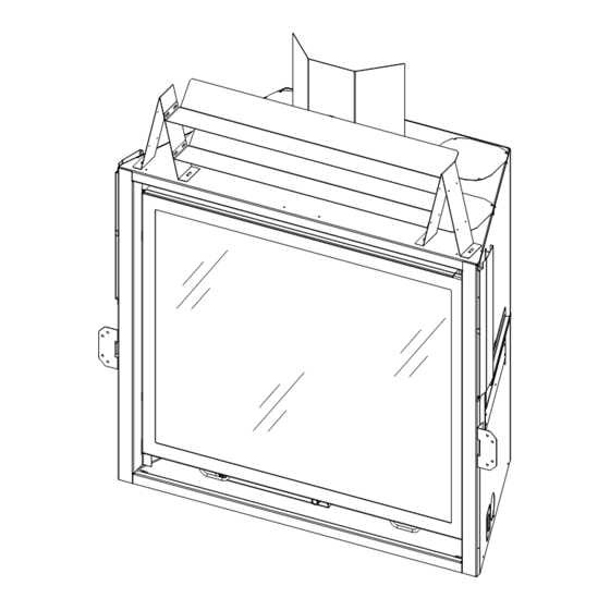
9.0 Fireplace Setup 9.1 Glass Frame Assembly 9.2 Bottom Frame Removal and Installation WARNING: Do not operate this fireplace with the glass To access the control module housing, the bottom frame will removed, cracked, or broken. Replacement of the glass need to be removed. -
Page 45: Light Kit
9.3 Light Kit 9.3.2 Install Light Bulbs - Back Bottom Light Kit ATTENTION: If converting to propane do so now before Note: The back bottom light kit will not have the halogen bulb installing any light kit components. Follow instructions in- installed from the factory. -
Page 46: Media Tray Base - Side Trim
9.4 Media Tray Base - Side Trim This fireplace contains side trim on the left and right side of the media tray base. 9.4.1 Fireplace Installation with no optional panel set or installation of NK36-BG900. Before installation of the log set, ember bed media make sure these components butt up against the firebox to ensure no light shines through from the bottom ember bed light kit. -
Page 47: Nk36-500 Log Set Installation
9.5 NK36-500 Log Set Installation NOTE: Log numbers are located on the bottom or side of each log. Refer to the following instructions and illustration for proper placement. Your components may look different than the ones shown. CAUTION: Do not place logs directly over burner port holes. Improper log placement may affect flame appearance and may cause excessive soot to build upon the glass. - Page 48 Figure 9.8 - Log Set 2 Figure 9.9 - Log Set 3 Hussong Mfg. Co, Inc. Rev. 1 - July 2023 NDK-36-DV - PFS Report No. 23-152 Starting Serial Number: 23 N36DV00001 38...
- Page 49 Figure 9.10 - Log Set 4 7. Install the crushed media on the ember bed and lava rock along the sides of the ember bed. 8. Place log #N36-6 on the left burner assembly by align- ing the pins on the burner and the holes in the bottom of the log.
- Page 50 9.5.1 Rockwool Installation • After installation of the log set you can apply rockwool across logs N36-6, N36-7, left & right burner screen and rear burner. • Use a small brush to brush the rockwool across the locations referenced above. Rockwool will provide a glow as the fireplace operates.
-
Page 51: Control Board Removal And Installation
9.6 Control Board Removal and Installation WARNING: If burner and/or pilot have been burning, use appropriate protection to avoid burns or damage to per- sonal property before removing any components. DO NOT OPERATE THIS APPLIANCE WITHOUT THE SEAL- ING GASKET (LOCATED UNDER THE CONTROL BOARD) IN PLACE. - Page 52 Figure 9.16 - Step 4 Figure 9.17 - Step 5 Figure 9.18 - Step 6 Hussong Mfg. Co, Inc. Rev. 1 - July 2023 NDK-36-DV - PFS Report No. 23-152 Starting Serial Number: 23 N36DV00001 38...
-
Page 53: Electrical Information
10.0 Electrical Information WARNING: Do not use this fireplace if any part has been under 10.2 Wiring Requirements water. Immediately call a qualified service technician to inspect this appliance and to replace any part of the control system and • The system requires 120 VAC of electricity and/or batter- any gas control which has been under water. -
Page 54: Operating Instructions
11.0 Operating Instructions Hussong Mfg. Co, Inc. Rev. 1 - July 2023 NDK-36-DV - PFS Report No. 23-152 Starting Serial Number: 23 N36DV00001 38... -
Page 55: Setup Proflame
11.1 Setup Proflame 2 IFC Module 11.3 Reset the System for Manual Operation Set the main ON/OFF rocker switch in the OFF posi- 1. Access the toggle switch and remote learn button on the tion. left side of the unit by removing the safety barrier screen by lifting up and out of its slots. -
Page 56: Control System 7 Day Timeout
11.7.1.2 Remote Control ON/OFF Key 11.6 Control System 7 Day Timeout 1. Press the remote control ON/OFF key to turn the sys- • If you have your Proflame 2 system set to CPI tem OFF. (continuous pilot ignition) with 7 consecutive days without ignition of the main burner, the pilot will turn 2. -
Page 57: Remote Control Operation
11.9 Remote Control Operation Figure 11.1 - Remote control overview 11.9.1 Temperature Display 11.9.2 Key Lock 1. With the system in the OFF position, simultaneously press This function locks the keys to avoid unsupervised opera- the thermostat key and the mode key to change degrees tion. - Page 58 11.9.3 Pilot Ignition Selection (IPI/CPI) 11.9.6 Remote Control Flame Adjustment This control system has (6) flame levels. If the smart thermo- This system has the option of a continuous (standing) stat operation is activated, then the manual adjustment of the pilot.
- Page 59 11.9.6.1 Deactivate Flame Modulation 11.9.7.2 Smart Thermostat Verify all (3) AAA batteries are installed in the remote The smart thermostat function will adjust the flame height control battery bay. based on the set temperature and the actual room tempera- ture. The smart thermostat function automatically adjusts the Remove (1) AAA battery.
- Page 60 11.9.8 Fan Speed Control 11.9.9 Top Accent Light Kit Fan speed can be adjusted through (6) speeds. To activate The top light intensity can be adjusted through (6) levels. this function, 1. Press the mode key to index to the light icon. ...
- Page 61 11.9.10 Activate Ember Bed Light Kit (auxiliary) 11.9.10.2 Deactivation AUX (Ember Bed Light Kit) The auxiliary function controls ON/OFF function the ember bed Verify all (3) AAA batteries are installed in the remote light kit. To activate this function, control battery bay. 1.
-
Page 62: Pressure Testing And Burner Adjustments
12.0 Pressure Testing and Burner Adjustments 12.1 Pressure Testing Table 12.1 Inlet Pressures NOTE: The appliance and its appliance main gas valve Fuel Natural Gas Propane must be disconnected from the gas supply piping system during any pressure testing of the system at test pres- Gas Supply Min-Max Min-Max... -
Page 63: Flame Appearance Adjustment
12.2 Flame Appearance Adjustment WARNING: To avoid property damage or personal injury, allow the fireplace ample time to cool before making any adjustments. Burner flame appearance and characteristics are affected by altitude, fuel quality, venting configuration, and other fac- tors. After installation, this appliance may need additional adjustments to achieve optimum flame appearance and visual aesthetics. - Page 64 12.2.3 Vent Restriction (after installation) Table 12.5 Restrictor Plate Adjustment Guidelines WARNING: To avoid property damage or personal injury, Flame Appearance Draft Problem Solution allow the fireplace ample time to cool before making any adjustments. WARNING: Improper vent installation may cause the burn- Short, flickering Excessive draft and/or Add restrictor plate...
-
Page 65: Troubleshooting
13.0 Troubleshooting ATTENTION: Troubleshooting must be performed by a qualified technician. Before proceeding with the steps in the following troubleshooting guide, • • Verify proper 120VAC power supply to the control Verify inlet pressure meets the recommended inlet pres- module. sure. - Page 66 Issue Cause Solution Burner flame will not light ON/OFF rocker switch in OFF position Switch rocker switch to ON position. Gas supply turned off Check for multiple shut-offs in the supply line. Verify gas supply is turned on. Low gas supply Consult with plumber or gas supplier.
- Page 67 Issue Cause Solution Flame burns blue and lifts off Improper venturi setting The venturi air shutter may need to be burner close slightly to allow less air into the gas mix. Refer to section 12.2.1, BURNER VEN- TURIS on page 62. Incorrect vent cap installation Adjust if necessary.
-
Page 68: Maintenance
14.0 Maintenance ATTENTION: Installation and repair should only done by a 14.3 Vent System qualified service person. The appliance should be inspect- ed before use and at least annually by a professional ser- NOTE: If the vent-air intake system is disassembled for any vice person. -
Page 69: Burner And Pilot System
14.5 Burner and Pilot System The burner assembly may be removed for easier access to the control compartment. See Section 9.6 Control Board Removal and Installation on page 50 for instructions. Verify gas supply is turned on and filled. Consult with plumber or gas supplier as necessary. -
Page 70: Replacement Parts List
15.0 Replacement Parts List Replacement parts are available through your local dealer. Contact your local dealer for availability and pricing. The following warning is for replacement parts for this appliance. ⚠ WARNING: This product can expose you to chemicals including Lead, which is [are] known to the State of California to cause cancer, birth defects P.O. - Page 71 Glass and Glass Parts Light Kits Glass with Gasket - 31 3/8” x 26 1/4” 701-005T 20W Halogen Bulb 600-676 1 1/8” Glass Gasket with Adhesive 900-006 Light Kit - Ember Bed NK36-LKT Replacement Valance NK36-005 Light Kit - Top NK36-TLK 1.5lb.
-
Page 72: Limited Lifetime Warranty
Hussong Manufacturing Company, Inc. (Hussong Mfg.) All parts and material except the items listed in the 30 day warrants this Kozy Heat gas appliance from the date of warranty and any exclusions or limitations that may apply purchase to the original purchaser, that it is free of defects in materials and workmanship at the time of manufacture. - Page 73 Limited Lifetime Warranty EXCLUSIONS AND LIMITATIONS (continued) 10. It is expressly agreed and understood that this warranty is Hussong Mfg.’s sole obligation and purchaser’s exclusive reme- dy for defective fireplace equipment. Hussong Mfg. is free of liability for any damages caused by this appliance, as well as inconvenience expenses and materials.
- Page 74 Hussong Mfg. Co, Inc. Rev. 1 - July 2023 NDK-36-DV - PFS Report No. 23-152 Starting Serial Number: 23 N36DV00001 38...
Need help?
Do you have a question about the Nordik 36 DV and is the answer not in the manual?
Questions and answers